Article

A Frequency Locking Method for ICPT System Based on LCC/S Compensation Topology

School of Electrical and Electronic Engineering, North China Electric Power University, Beijing 102206, China
*
Author to whom correspondence should be addressed.
Energies 2019, 12(13), 2626; https://doi.org/10.3390/en12132626
Submission received: 17 June 2019 / Revised: 3 July 2019 / Accepted: 6 July 2019 / Published: 8 July 2019
(This article belongs to the Special Issue Intelligent Wireless Power Transfer System and Its Application)

Abstract

:
Aiming to maximize the transmission efficiency of inductively coupled power transmission (ICPT) system with the designed output power, a frequency locking method for an ICPT system based on LCC/S compensation topology is proposed in this paper. Firstly, the relationship between compensation component Lf1 and output power was deduced by the lossless model, and the initial value of Lf1 was obtained. Then, considering the system loss, the designed output power and frequency were input into the frequency locking program, and Lf1 and other compensation parameters were dynamically tracked. At the same time, the transmission efficiency of the system was calculated, and the frequency that achieved maximum efficiency was automatically locked when the system met the requirements of the designed output power. Finally, based on the method, the output characteristics of the system were verified by experiments.

1. Introduction

Inductively coupled power transmission technology uses the alternating magnetic field generated by the transmitting coils to couple the energy to the receiving coils so as to realize the wireless power transmission. Its non-contact power transmission characteristics make it convenient, safe, adaptable, so it is widely used in various fields such as biomedicine, electric vehicles and so on [1,2,3].
Compensation topology is an important aspect in ICPT systems because it can increase the power transfer ability, minimize the reactive power rating of the power source, and help achieve soft switching of the power in electronics devices [4]. There are four basic topologies depending on how the compensation capacitors are added to the primary and secondary coils, namely, series-series (SS), series-parallel (SP), parallel-series (PS), and parallel-parallel (PP) topologies [5,6]. In these four compensation topologies, the power transfer ability of ICPT system cannot be used to increase the transmission power when the load resistance is fixed because of the effect of the parameters of the loosely coupled transformer. More advantageous topologies have been forward to solve this problem by increasing the order of equivalent circuit in References [7,8]. LCC third-order topology is an outstanding method since the resonant frequency is independent of the parameters of loosely coupled transformer [8]. The doubled-side LCC compensation topology has been studied in depth by many scholars [9,10,11,12,13,14]. The double-sided LCC compensation is less sensitive to the variations of self-inductances caused by the change in the relative position of the primary and secondary coils [9]. The LCC compensation network has the least consumption of reactive power than CLC and four-coil structure [10]. A close-cycle transfer control strategy has been investigated to realize transmission from CC (constant current) mode to CV (constant voltage) mode for IPT EV (electric vehicle) charging system [11]. However, the use of multiple reactive devices makes its transmission efficiency limited and increases the system cost and volume [12]. The literature [13,14] discusses the power loss model of the WPT system with doubled-side LCC compensation topology, expounding the necessity of considering loss. The literature [15] has designed a value for the compensation component Lf1 and resonant frequency respectively and then calculates the parameters of other compensation components. However, the model does not consider the loss, and the resonant frequency value that the literature choose is lack of reasons. There is no locking process of the resonant frequency.
Aiming to maximize the transmission efficiency of the ICPT system with designed output power, a frequency locking method for ICPT system based on LCC/S compensation topology is proposed in the paper. Firstly, the expression of output power was deduced by establishing a lossless model to get the initial value of Lf1. Then, considering the loss, the output power was calculated by establishing a loss model to adjust Lf1 until the output power reaches the design value. The equivalent parameters and magnetic flux density distribution of the loosely coupled transformer were obtained by finite element simulation analysis. When the output power was fixed, different frequencies correspond to different Lf1 values. By comparing the transmission efficiency of different combinations of frequency and Lf1, the optimal combination was obtained, which maximized the transmission efficiency of the system with the designed output power, completing frequency locking and parameter design of LCC/S compensation structure.

2. Analysis of LCC/S Compensation

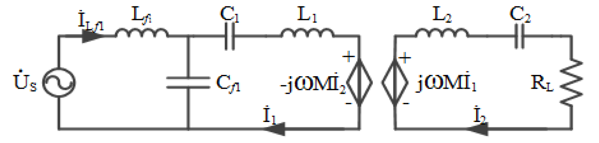
2.1. The Lossless Model of LCC/S Compensation

The proposed LCC/S compensation topology is shown in Figure 1. Lf1, Cf1 and C1 are the primary-side compensation inductor and capacitors, respectively. C2 is the secondary-side compensation capacitor. L1 and L2 are the self-inductances of the primary coils and secondary coils, respectively. M is the mutual inductance between the primary and secondary coils. j ω M I ˙ 2 and j ω M I ˙ 1 are reflected voltages from secondary and primary. ILf1, I1 and I2 are the currents on Lf1, L1 and L2, respectively. US is the input voltage applied to the compensated coil.
According to LCC compensation topology [8], the resonant frequency ω 0 should be
ω 0 = 1 L f 1 C f 1 = 1 ( L 1 L f 1 ) C 1 = 1 L 2 C 2
When the system is in resonance, the secondary-side impedance Zsec, the reflected impedance Zref, and the input impedance Zin can be simplified as follows:
Z s e c = j ω 0 L 2 + 1 j ω 0 C 2 + R L = R L
Z r e f = j ω 0 M I 2 I 1 = ω 0 2 M 2 R L
Z i n = j ω 0 L f 1 + 1 j ω 0 C f 1 ( j ω 0 L 1 + 1 j ω 0 C 1 + Z r e f ) = L f 1 2 R L M 2
According to Equation (4), the input current of this compensation topology is
I i n = U S Z i n = U S M 2 L f 1 2 R L
From Equation (5), it is obvious that Iin is in phase with US, zero phase angle is achieved and no reactive power is needed from the power source.
In the lossless model, the system is considered to have no power loss. So the input power equals to the output power, and the transmission power of this system is given by
P o u t = P i n = U S 2 Z i n = U S 2 M 2 L f 1 2 R L .
It can be seen that the output power is proportional to the square of the input voltage US and the square of the mutual inductance M. The output power is inversely proportional to the load RL and the square of the compensation inductance Lf1. When the loosely coupled transformer parameters are fixed, the transmission power can be adjusted by adjusting the value of the compensation inductance Lf1.
It is known that P o u t can be obtained in Equation (6) when not considering the power loss. In addition, we have P o u t = U o u t 2 R L . Therefore, the output voltage and output current are given by
U o u t = P o u t R L = U S M L f 1
I o u t = U o u t R L = U S M R L L f 1 .
From Equations (7) and (8), it is obvious that the output voltage and output current are in phase. The unit power factor for the output rectifier is also achieved. Moreover, the output voltage does not rely on the load RL, ICPT system with LCC/S compensation has constant voltage output characteristics.

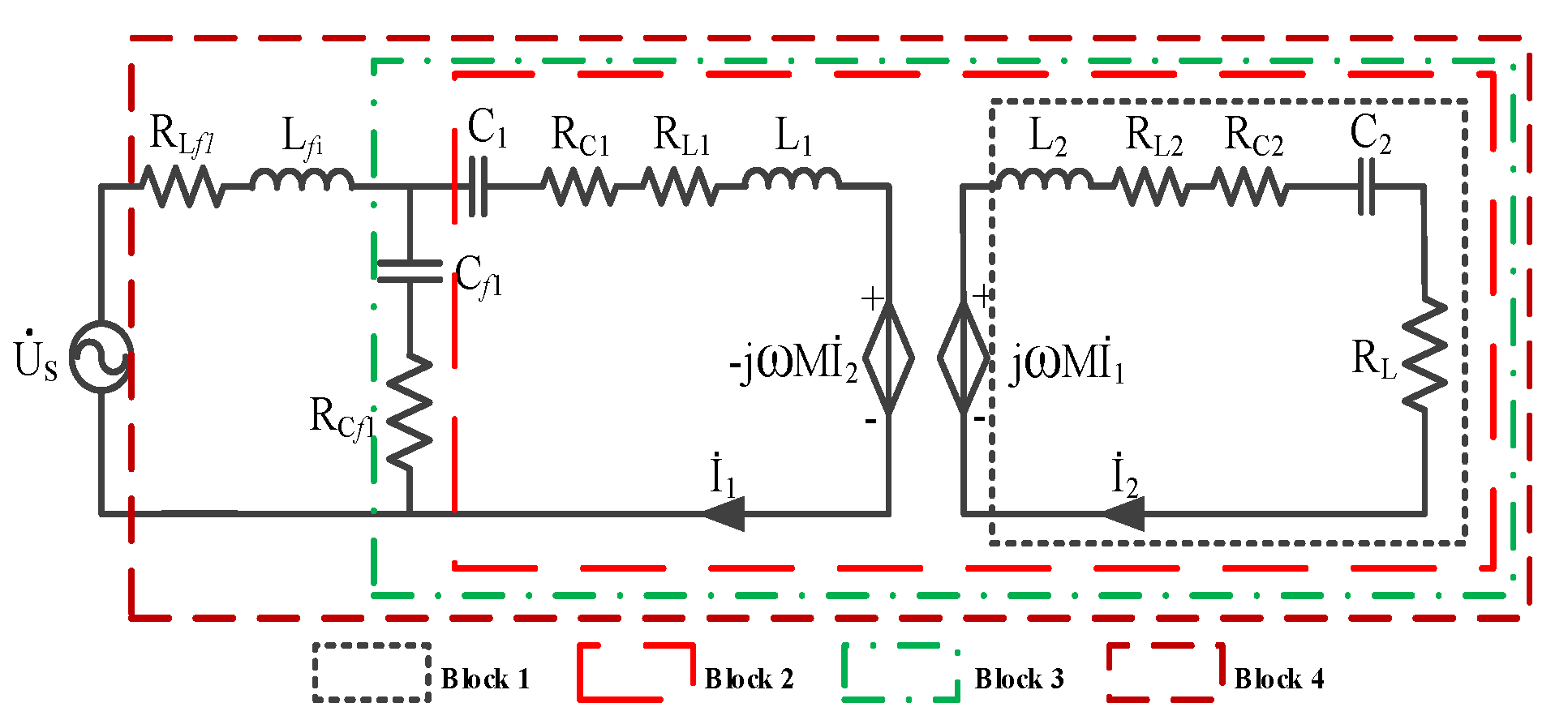
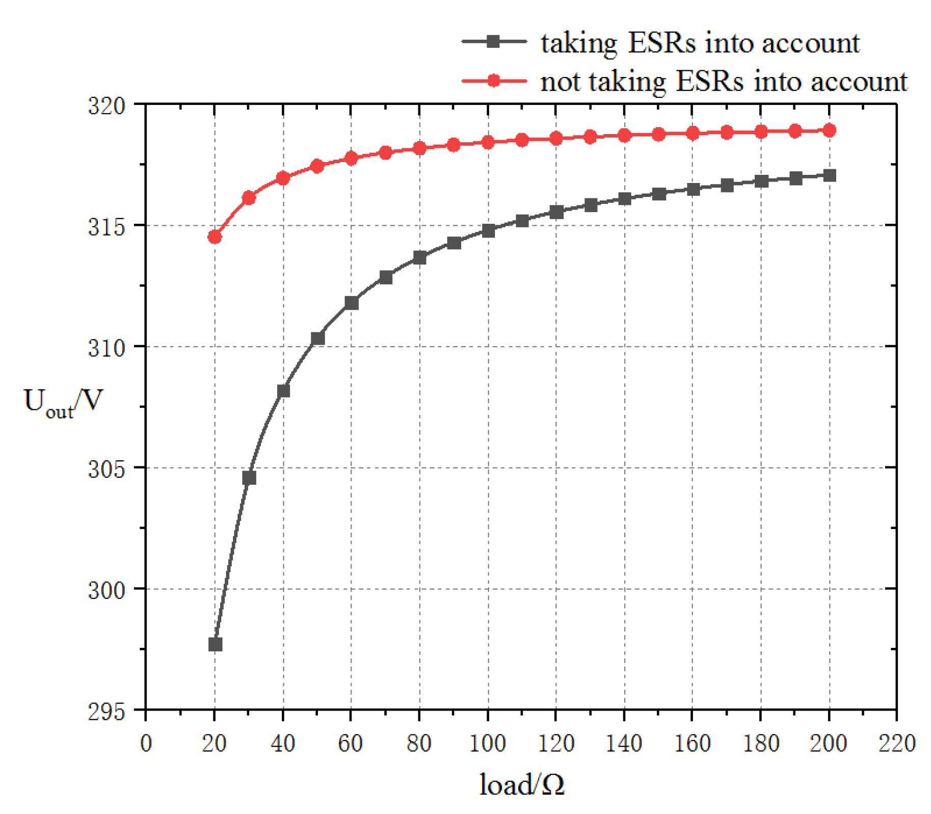
2.2. The Loss Model of LCC/S Compensation

According to Equation (6), once the input voltage, the mutual inductance, the compensation inductance and the load are determined, the system power value is fixed. Moreover, if the resonance frequency is changed, the matching network will also change to reflect this frequency change. The system is required to achieve the highest efficiency at the desired output power and the compensated inductance values can be optimized at that point.
When the transmission power of the ICPT system is fixed, the transmission efficiency of the system will depend on the power loss, which will be closely related to the equivalent series resistances (ESRs) of each component in the LCC/S compensation topology. The ESRs of inductances are closely related to the quality factors of the inductances, the inductances values, and the operating frequency. The ESRs of capacitances are closely related to the dissipation factors of the capacitance, the capacitance values, and the operating frequency. The expressions of ESRs are given by
R L f 1 = ω L f 1 Q f 1
R C f 1 = D F ω C f 1 R C 1 = D F ω C 1 R C 2 = D F ω C 2
where Qf1 stand for the quality factors of Lf1, which can be approximated at 200 based on their inductance values. DF is the dissipation factor of the capacitors, which can be approximated at 0.05% [13,14]. RL1 and RL2 are the AC resistances of the primary coils and secondary coils, respectively.
Figure 2 shows the equivalent circuit with ESRs. The efficiency analysis can be done separately. The total efficiency ηLCCS is the product of η1, η2, η3, η4. As shown in Figure 2, η1 stands for the efficiency of Block 1, which is the ratio of real power obtained by the load over the real power entering into Block 1. η2 stands for the efficiency of Block 2, which is the ratio of real power entering into Block 1 over the real power absorbed by Block 2; η3 stands for the efficiency of Block 3, which is the ratio of real power entering into Block 2 over the real power absorbed by Block 3; η4 stands for the efficiency of Block 4, which is the ratio of real power entering into Block 3 over the real power absorbed by Block 4. The expressions of η1, η2, η3, η4 are shown below respectively.
η 1 = R L R L + R C 2 + R L 2
η 2 = R r e f R r e f + R C 1 + R L 1
η 3 = | R C f 1 + 1 j ω C f 1 | 2 ( R C 1 + R L 1 + R r e f ) | R C f 1 + 1 j ω C f 1 | 2 ( R C 1 + R L 1 + R r e f ) + | R C 1 + R L 1 + Z r e f + 1 j ω C 1 + j ω L 1 | 2 R C f 1
η 4 = Re ( Z b l o c k 3 ) R L f 1 + Re ( Z b l o c k 3 )
where Zblock3, Zref are respectively the impedances of Block 3 and the reflected impedance to the primary side. Rref is the reflected resistance to the primary side.
Therefore, the total efficiency of the system can be gain by the product of Equations (11), (12), (13) and (14), providing a theoretical basis for calculating transmission efficiency in the frequency locking method. However, the parameters of the loosely coupled transformer in the above formulas are still unknown. In order to obtain the primary and secondary inductances, AC resistances and mutual inductances of the transformer, the finite element simulation of the loosely coupled transformer is needed to carry out, as shown below.

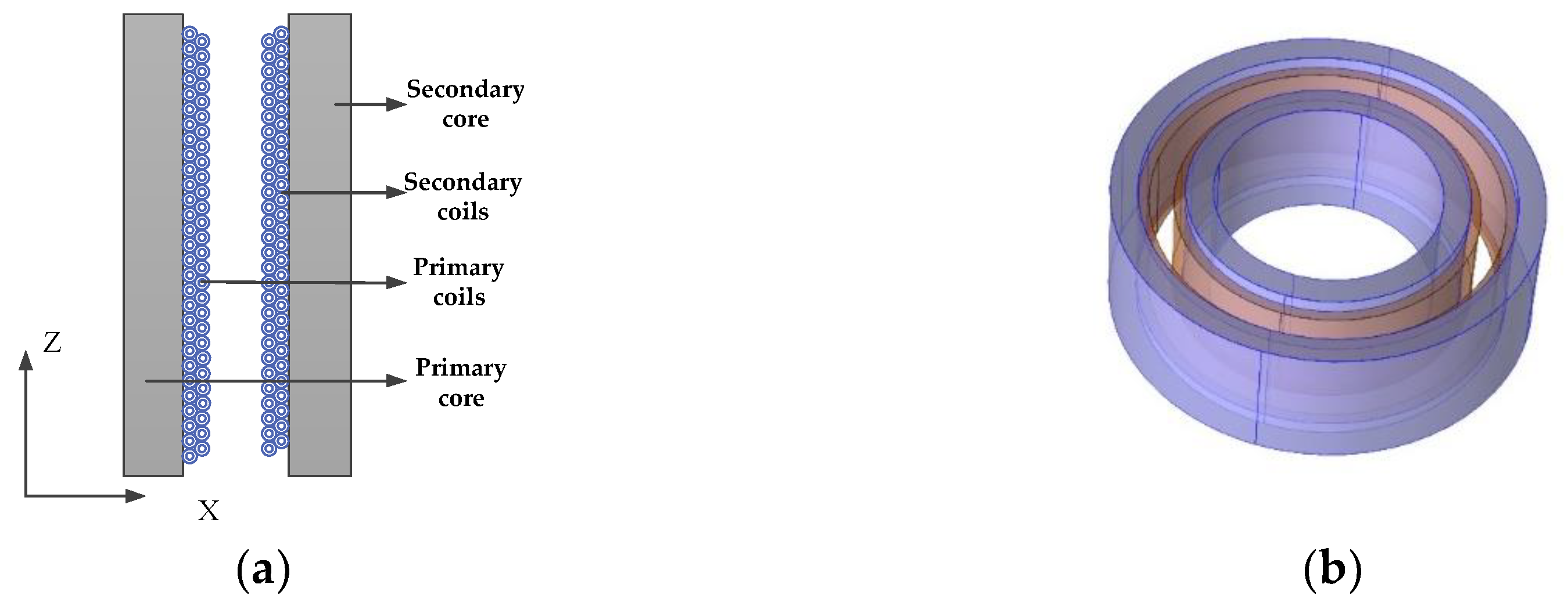
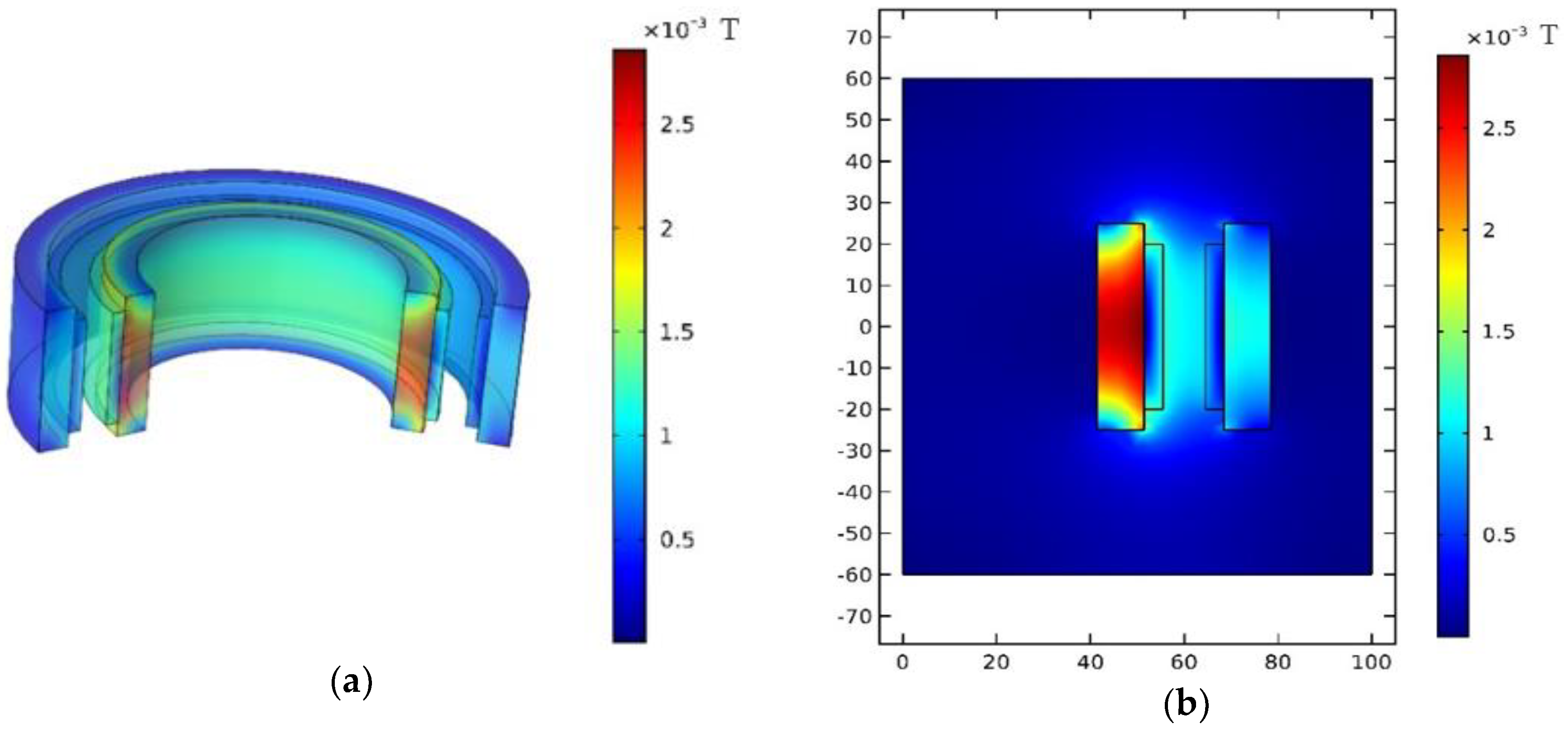
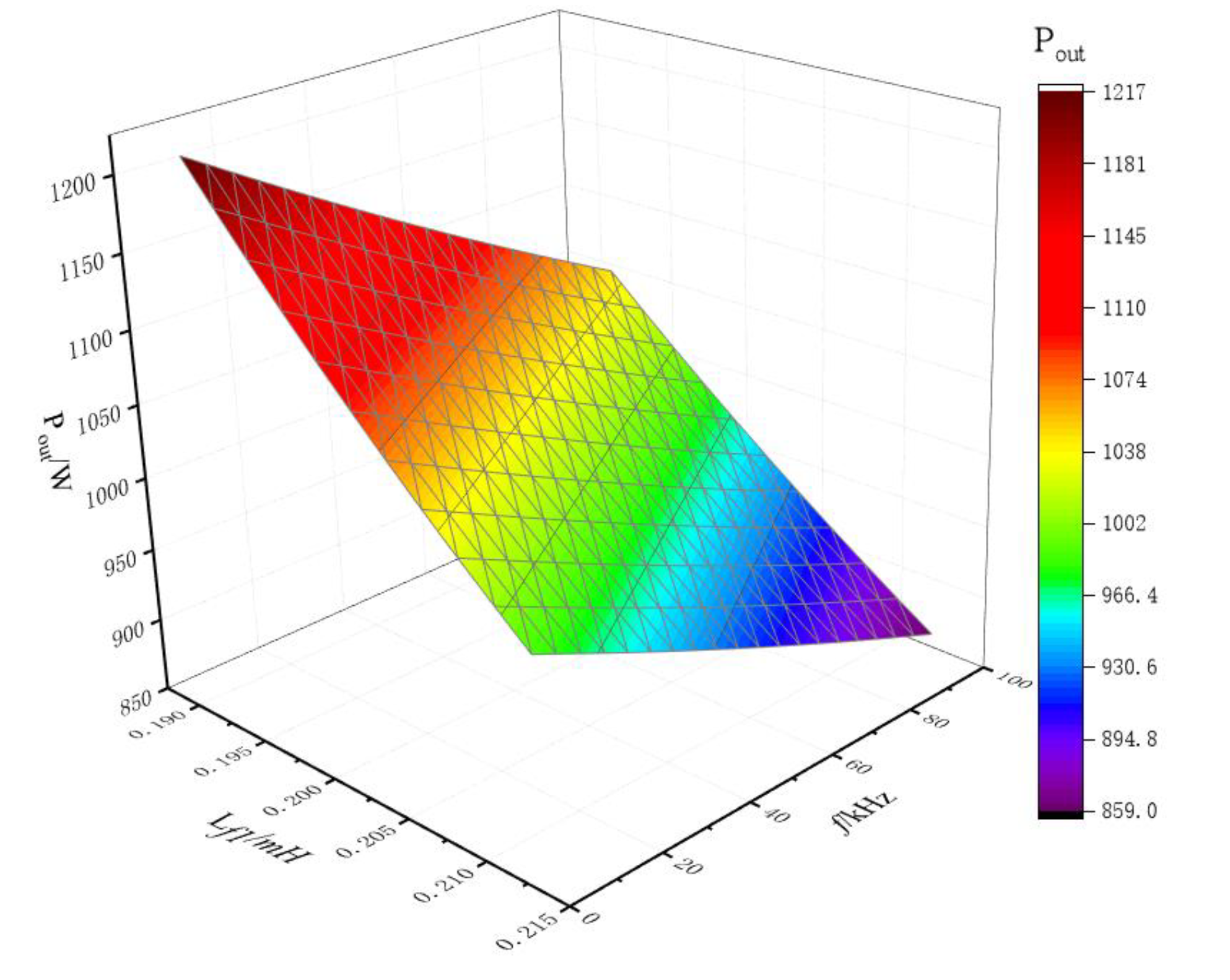
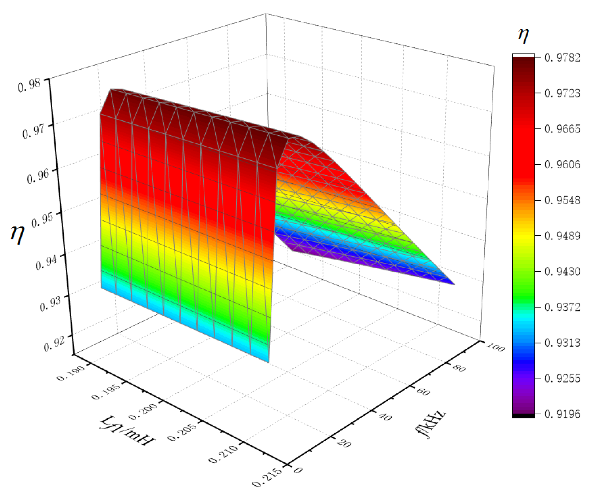
3. Analysis of Finite Element Simulation

The finite element simulation software COMSOL was used in this paper to construct LCC/S compensation network based on the axial loosely coupled transformer. Axial loosely coupled transformer model was first established, and the primary and secondary inductances and mutual inductances of the transformer were determined through the no-load and short-circuit experiments inside the COMSOL. Then, the component parameters of the compensation structure were calculated according to the obtained transformer structural parameters, and then the entire ICPT system including the compensation structure was completed.
Figure 3 is the schematic diagram of the axial loosely coupled transformer and the model in the finite element simulation software COMSOL. It is mainly composed of primary and secondary cores and primary and secondary coils, the inner core and the inner coils are the primary parts, and the outer core and the outer coils are the secondary parts. The geometric parameters of the axial loosely coupling transformer are shown in Table 1.
According to the structure diagram shown in Figure 4, an ICPT simulation platform was built. The entire system included five parts: high-frequency power supply, primary compensation, loosely coupled transformer, secondary compensation and load. The primary and secondary compensations were achieved through the ‘coils’ in COMSOL to realize the real-time coupling of the compensation circuits and the loosely coupled transformer.
Figure 5 shows the distribution of magnetic flux density. Figure 5a shows the distribution of the magnetic flux density of the three-dimensional model, and Figure 5b shows the distribution of the magnetic flux density of the two-dimensional axisymmetric model.
In the COMSOL simulation, L1 and RL1 can be estimated by opening the secondary side and applying the rated voltage to the primary side. L2 and RL2 can be measured by opening the primary side and applying the rated voltage to the secondary side. Mutual inductance M can be measured by a short circuit on the secondary side and applying rated current to the primary side. The results of the primary and secondary inductances, AC resistances and mutual inductances of the transformer were: L1 = 0.84 mH; L2 = 0.76 mH; M = 0.67 mH; RL1 = 0.27 Ω; RL2 = 0.31 Ω. The coupling coefficient between the primary and secondary sides was 0.839.

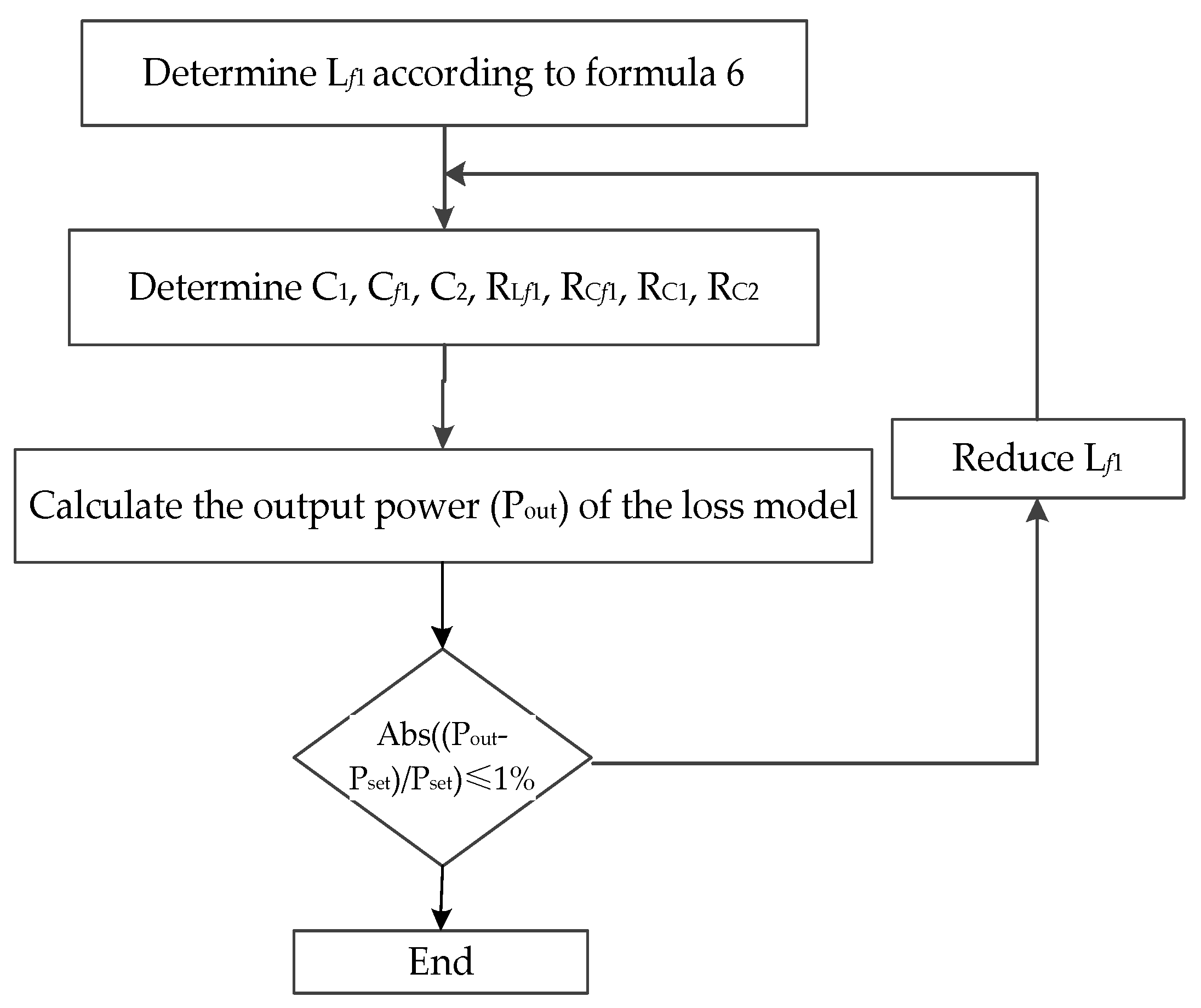
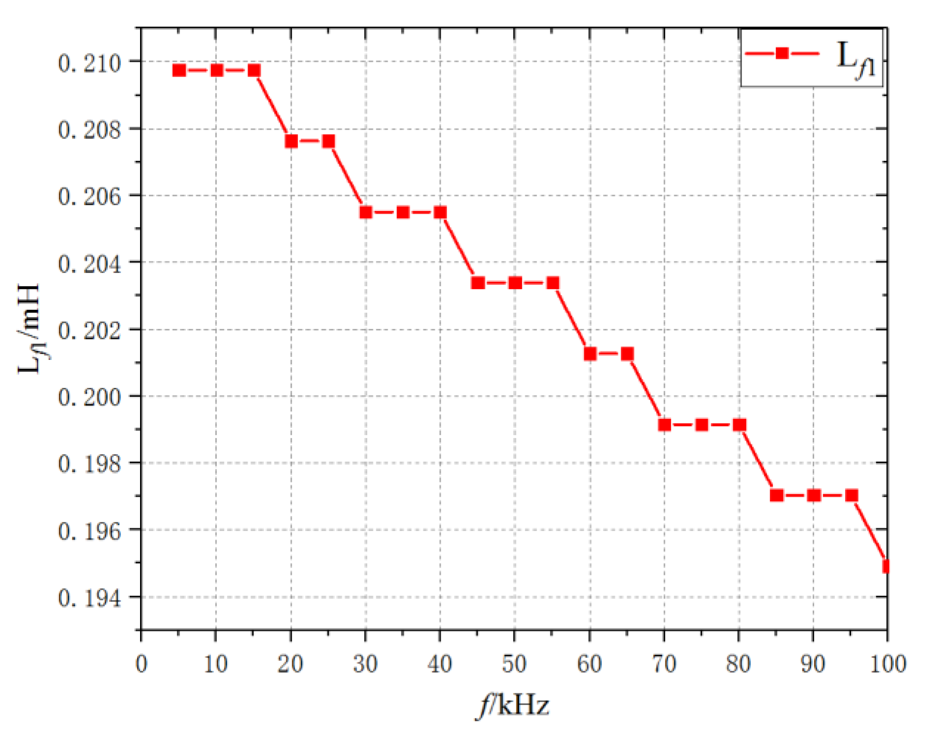
4. Frequency Locking Method

From Equation (6), the output power is related to Lf1, while Lf1 is related to the resonant frequency, so the output power is indirectly related to the resonant frequency. When the transmission capacity is determined, the loss of the system can be reduced by changing the resonant frequency, thus the transmission efficiency will be improved.
When the required power is set, the inductance Lf1 can be determined by Equation (6). However, the output power will be less than the set value (Pset) when taking the loss of the system into account, so the inductance Lf1 must be adjusted. The design procedures can be summarized in the flowchart as shown in Figure 6.
Substituting the initial Lf1 into Equations (1), (9) and (10), C1, Cf1, C2, RLf1, RCf1, RC1 and RC2 can be calculated. The values of each compensation component and its equivalent series resistance were substituted into the Figure 2, the output power (Pout) of the whole ICPT system can be calculated. If the absolute value of the difference between Pout and Pset is greater than the setting tolerance (1% was set in this paper), the value of Lf1 will be decreased to re-enter the loop. Otherwise, the loop will be terminated.
The output power and efficiency of the ICPT system can be obtained by applying Equations (9), (10), (11), (12), (13) and (14) in the MATLAB. For our case, the desired output power was 1 kW and the load is 100 Ω. Figure 7 shows the output powers with the compensation inductance Lf1 and resonant frequency. Figure 8 shows the efficiencies with the compensation inductance Lf1 and resonant frequency. Output power decreases with the increase of compensation inductance and resonant frequency and transmission efficiency increases first and then decreases with the increase of resonant frequency. When the resonant frequency was within 5 kHz to 100 kHz, the efficiency of the entire ICPT system varied within 0.919–0.978. Therefore, there must be a combination of compensation inductance and resonant frequency, which can maximize the transmission efficiency while allowing the ICPT system to transmit 1 kW.
Figure 9 shows the curve of the compensation inductance Lf1 with the resonant frequency when the output power was 1 kW. From the picture, the value of compensation inductance Lf1 decreased as the frequency increased. Figure 10 shows the curve of the efficiency with resonant frequency at the output power of 1 kW, where the compensation inductance is the value in Figure 9. From Figure 10, the transmission efficiency increases first and then decreases with the increase of the resonant frequency. The peak value of the transmission efficiency curve is the highest efficiency that the ICPT system can achieve, which was 97.8%. The value of the resonant frequency at this point is the optimal frequency value, which was 15 kHz.
Figure 11 shows the relationships between the output voltage and load resistance when the resonant frequency was 15 kHz, considering loss and not considering loss respectively. As can be seen from the figure, when the loss is considered, the output voltage is smaller and the output voltage change rate is larger. Therefore, the influence of loss is necessary to be considered when discussing LCC/S compensation. When considering the loss, the output voltage change rate was less than 0.7% in the load resistance range of 80–200 Ω, showing that the system had good output voltage stability.

5. Experimental Verification

Based on the previous simulation analysis, the constant voltage, large capacity and high-efficiency transmission characteristics of LCC/S compensation were experimentally verified. The results before and after compensation were compared.

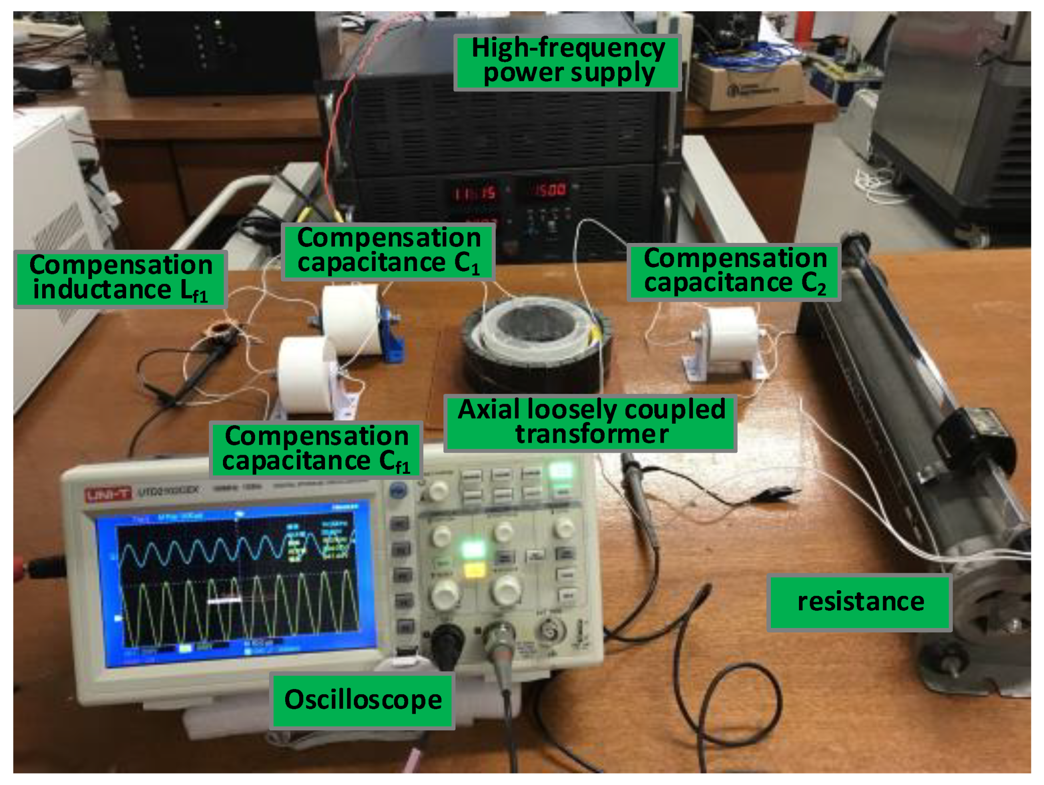
5.1. Construction of ICPT System Experimental Platform

Figure 12 is the ICPT experimental platform with LCC/S compensation structure. The instruments needed for the experiment are: (1) a high-frequency power supply that ranges from 3 kHz to 120 kHz in frequency and from 0 V to 120 V in voltage; (2) an axial loosely coupled transformer; (3) high-frequency and high-voltage compensation elements L f 1 , C f 1 , C 1 , C 2 , which are resonant with loosely coupled transformer parameters; (4) oscilloscope; (5) resistance. Setting the frequency of the high-frequency power supply at 15 kHz and the voltage at 100 V.

5.2. Verification of Constant Voltage Output Characteristic of LCC/S Compensation

The output voltage before and after compensation varied with load resistance is shown in Table 2 (due to the limitation of power supply capacity, only 100–140 Ω load resistance experiments have been carried out). We can know that when the load resistance was 100 Ω, the output voltage was 72.6 V before compensation, but it increased considerably to 294.2 V after LCC/S compensation. When the load resistance varied in the range of 100 to 140 Ω, the maximum voltage variation rate was 6.17% before compensation, but it decreased obviously to 1.87% after LCC/S compensation. Therefore, by LCC/S compensation, not only the output voltage of the system can be increased, but also the voltage variation rate can be smaller.

5.3. Verification of Large-capacity and High-efficiency Transmission Characteristic of LCC/S Compensation

As shown in Table 3, when the load resistance varied in the range of 100 to 140 Ω and the system frequency was at 15 kHz, the output power before and after compensation was compared (due to the limitation of power supply capacity, only 100–140 Ω load resistance experiments have been carried out). It can be known that after LCC/S compensation, the output power of the ICPT system was significantly greater than that before compensation, and the transmission efficiency was up to 92.16% when the load was 100 Ω. With the increase of load resistance, the transmission power and efficiency of the compensated ICPT system decreased, which is in agreement with Equation (6). Therefore, the experiment shows that LCC/S compensation can greatly improve the transmission power of the ICPT system and get a high level of transmission efficiency.

6. Conclusions

The paper proposes a frequency locking method for ICPT system based on LCC/S compensation topology. The relationships between the parameters of each compensation component in LCC/S compensation are given. Based on this, the output characteristics were derived and the calculation method of the efficiency of the ICPT system is given. In order to achieve efficient operation of the ICPT system, the optimal frequency locking method under constant output power is proposed through the synergy between resonant frequency and compensation inductance. A 1 kW ICPT system was designed and built using the method proposed in this paper. The efficiency of the simulated system was up to 97.8%. At last, the ICPT experiments show that by LCC/S compensation and optimal frequency locking, the system can get a nearly constant output voltage and greatly larger transmission power.

Author Contributions

All authors have worked on this manuscript together and all authors have read and approved the final manuscript.

Funding

This research was funded by the National Natural Science Foundation of China, grant number 51277066

Conflicts of Interest

The authors declare no conflict of interest.

References

  1. Smeets, J.P.C.; Overboom, T.T.; Jansen, J.W.; Lomonova, E.A. Comparison of Position-Independent Contactless Energy Transfer Systems. IEEE Trans. Power Electron. 2012, 28, 2059–2067. [Google Scholar] [CrossRef]
  2. Chen, Q.; Wong, S.C.; Chi, K.T.; Ruan, X. Analysis, Design, and Control of a Transcutaneous Power Regulator for Artificial Hearts. IEEE Trans. Biomed. Circuits Syst. 2009, 3, 23. [Google Scholar] [CrossRef] [PubMed]
  3. Covic, G.A.; Boys, J.T. Modern Trends in Inductive Power Transfer for Transportation Applications. IEEE J. Emerg. Sel. Top. Power Electron. 2013, 1, 28–41. [Google Scholar] [CrossRef]
  4. Zhang, W.; Mi, C.C. Compensation Topologies of High-Power Wireless Power Transfer Systems. IEEE Trans. Veh. Technol. 2016, 65, 4768–4778. [Google Scholar] [CrossRef]
  5. Wang, C.S.; Stielau, O.H.; Covic, G. Design considerations for a contactless electric vehicle battery charger. IEEE Trans. Ind. Electron. 2005, 52, 1308–1314. [Google Scholar] [CrossRef]
  6. Alireza, K.; Dusmez, S. Comprehensive Topological Analysis of Conductive and Inductive Charging Solutions for Plug-In Electric Vehicles. IEEE Trans. Veh. Technol. 2012, 61, 3475–3489. [Google Scholar]
  7. Pantic, Z.; Bai, S.; Lukic, S.M. ZCS LCC-Compensated Resonant Inverter for Inductive-Power-Transfer Application. IEEE Trans. Ind. Electron. 2011, 58, 3500–3510. [Google Scholar] [CrossRef]
  8. Li, S.; Li, W.; Deng, J.; Nguyen, T.D.; Mi, C.C. A Double-Sided LCC Compensation Network and Its Tuning Method for Wireless Power Transfer. IEEE Trans. Veh. Technol. 2015, 64, 2261–2273. [Google Scholar] [CrossRef]
  9. Li, W.; Zhao, H.; Deng, J.; Li, S.; Mi, C.C. Comparison Study on SS and Double-Sided LCC Compensation Topologies for EV/PHEV Wireless Chargers. IEEE Trans. Veh. Technol. 2016, 65, 4429–4439. [Google Scholar] [CrossRef]
  10. Luo, S.; Li, S.; Zhao, H. Reactive power comparison of four-coil, LCC and CLC compensation network for wireless power transfer. In Proceedings of the Emerging Technologies: Wireless Power Transfer IEEE, Chongqing, China, 20–22 May 2017; pp. 268–271. [Google Scholar]
  11. Lu, J.H.; Lin, P.; Li, X.K.; Li, W.J.; Zhu, G.R.; Wong, S.C.; Jiang, J.; Liu, F. Research on seamless transfer from CC to CV modes for IPT EV charging system based on double-sided LCC compensation network. In Proceedings of the Energy Conversion Congress and Exposition IEEE, Milwaukee, WI, USA, 18–22 September 2016; pp. 1–6. [Google Scholar]
  12. Lu, F.; Zhang, H.; Kan, T.; Hofmann, H.; Mei, Y.; Cai, L.; Mi, C. A high efficiency and compact inductive power transfer system compatible with both 3.3kW and 7.7kW receivers. In Proceedings of the Applied Power Electronics Conference and Exposition IEEE, Tampa, FL, USA, 26–30 March 2017; pp. 3669–3673. [Google Scholar]
  13. Kan, T.; Nguyen, T.D.; White, J.C.; Malhan, R.K.; Mi, C.C. A New Integration Method for an Electric Vehicle Wireless Charging System Using LCC Compensation Topology: Analysis and Design. IEEE Trans. Power Electron. 2017, 32, 1638–1650. [Google Scholar] [CrossRef]
  14. Lu, F.; Zhang, H.; Hofmann, H.; Mi, C. A high efficiency 3.3 kW loosely-coupled wireless power transfer system without magnetic material. In Proceedings of the Energy Conversion Congress and Exposition IEEE, Montreal, QC, Canada, 20–24 September 2015; pp. 2282–2286. [Google Scholar]
  15. Li, B.; Zhu, G.; Lu, J.; Li, W.; Kumar, G.R.; Wang, J. Output characteristics of LCC-S compensation network and its optimal parameters design in IPT system. J. Eng. 2017, 2017, 1576–1579. [Google Scholar] [CrossRef]
Figure 1. Inductively coupled power transmission system with LCC/S compensation topology.
Energies 12 02626 g001
Figure 2. The equivalent circuit with ESRs.
Energies 12 02626 g002
Figure 3. Axial loosely coupled transformer. (a) Two-dimensional axisymmetric model;(b) three-dimensional model.
Energies 12 02626 g003
Figure 4. Structure diagram of the ICPT system simulation.
Energies 12 02626 g004
Figure 5. The distribution of magnetic flux density. (a) Three-dimensional model; (b) two-dimensional axisymmetric model.
Energies 12 02626 g005
Figure 6. Flowchart of compensation parameters design.
Energies 12 02626 g006
Figure 7. Output powers with the compensation inductance Lf1 and resonant frequency.
Energies 12 02626 g007
Figure 8. Efficiencies with the compensation inductance Lf1 and resonant frequency.
Energies 12 02626 g008
Figure 9. Curve of the compensation inductance with different resonant frequency when the output power is 1 kW.
Energies 12 02626 g009
Figure 10. Curve of the efficiency with a different resonant frequency.
Energies 12 02626 g010
Figure 11. Curves of the output voltage with different load.
Energies 12 02626 g011
Figure 12. ICPT experimental platform with LCC/S compensation structure.
Energies 12 02626 g012
Table 1. Geometric parameters of the axial loosely coupling transformer.
Geometric ParameterValue
The inner diameter of the primary core/mm83
The outer diameter of the primary core/mm103
The inner diameter of secondary core/mm137
The outer diameter of secondary core /mm157
Height/mm50
Turns of coil46/46
Table 2. The output voltage before and after compensation.
Load/Ω100110120130140
Voltage before compensation/V72.673.173.974.976.1
Voltage variation rate before compensation/%00.691.796.174.82
Voltage after compensation/V294.2295.6296.8298.1299.7
Voltage variation rate after compensation/%00.480.881.331.87
Table 3. Power and efficiency after compensation.
Load/Ω100110120130140
Output power before compensation/W52.7148.5844.9643.1541.37
Output power after compensation/W865.54794.36734.09683.57641.57
Input power after compensation/W939.19877.66836.48813.10802.26
Efficiency after compensation/%92.1690.5187.7684.0779.97

