Article

Multi-DOF WEC Performance in Variable Bathymetry Regions Using a Hybrid 3D BEM and Optimization

1
School of Naval Architecture and Marine Engineering, National Technical University of Athens, 15780 Athens, Greece
2
Department of Mechanical Engineering, University Dunarea de Jos of Galati, 800008 Galați, Romania
*
Author to whom correspondence should be addressed.
Energies 2019, 12(11), 2108; https://doi.org/10.3390/en12112108
Submission received: 9 April 2019 / Revised: 18 May 2019 / Accepted: 29 May 2019 / Published: 1 June 2019
(This article belongs to the Special Issue Renewable Energy in Marine Environment)

Abstract

:
In the present work a hybrid boundary element method is used, in conjunction with a coupled mode model and perfectly matched layer model, for obtaining the solution of the propagation/diffraction/radiation problems of floating bodies in variable bathymetry regions. The implemented methodology is free of mild-slope assumptions and restrictions. The present work extends previous results concerning heaving floaters over a region of general bottom topography in the case of generally shaped wave energy converters (WECs) operating in multiple degrees of freedom. Numerical results concerning the details of the wave field and the power output are presented, and the effects of WEC shape on the optimization of power extraction are discussed. It is demonstrated that consideration of heave in combination with pitch oscillation modes leads to a possible increase of the WEC performance.

1. Introduction

Renewable energy from the oceans is increasingly attracting the interest of the scientific and industrial society. Wave energy converters are constantly being deployed in areas characterized by increased potential, and a recent review concerning point absorber wave energy harvesters is presented in [1]. The performance of the devices installed in the nearshore and coastal environment, where the bottom terrain may present significant variations, can be evaluated by formulating and solving interaction problems of free surface gravity waves, floating bodies, and the seafloor; see, e.g., Wehausen [2] and Mei [3]. A thorough presentation of the interaction between waves and oscillating energy systems can be found in Falnes [4]. Models describing coupling methodologies for numerical modelling of near and far-field effects of wave energy converter arrays are presented in various works; see, e.g, [5,6,7].
The power efficiency and the operation of the WECs is affected by the bottom topography due to the local entrapped modes and of their impact on the wave propagation, with non-negligible results, especially in array layouts; see [5,8,9]. This is also demonstrated in wave propagation over variable seabed topographies or abrupt bathymetries including coastal structures; see, e.g., [10,11].
The numerical method implemented in this work for the treatment of the hydrodynamic problems simulating the WEC operation is a hybrid boundary element method coupled with a perfectly matched layer (BEM-PML) technique, which is used in conjunction with a coupled mode system for the simulation of the propagating waves over general seabed topography, as presented and validated in [12,13]. For the calculation of the propagation wave field over general 3D bottom topographies, including possibly steep parts, the coupled mode model (CMM), developed in [14] and extended for the 3D-domains in [15,16], is applied. The latter method is validated by comparisons against experimental data [17,18] and calculations obtained by the phase-averaged wave model SWAN (simulating waves nearshore) [19]. The boundary element method is then implemented for the calculation of the excitation loads on the floating body, along with the hydrodynamic coefficients of added mass and damping by utilizing the 3D Green’s Function, while the perfectly matched layer model is numerically treating the behavior of the outgoing radiating waves at large distances from the floating body [20].
The present method is applied to derive numerical results concerning the details of the wave field and the power output. Different axisymmetric WEC-shapes and power take off (PTO) configurations are examined, and the effects on the optimization of wave energy extraction are discussed. Following previous investigations, as reported in detail by Falnes [4], the consideration of additional degrees of freedom could significantly enhance the performance of a oscillating floating WEC. By using the present hybrid BEM, it is demonstrated that consideration of heave in combination with pitch modes leads to a substantial increase of the WEC performance, up to 300%. What is more important is that the consideration of additional degrees of freedom has an important effect on the determination of the optimal shape of the floater. Finally, the present model supports the application to more complex optimization problems, associated with multi DOF (degree of freedom) WEC performance, which are expected to be excited in variable bathymetry due to general wave incidence, in conjunction with depth inhomogeneity effects.

2. Formulation

2.1. Heaving Cylinder over Variable Bathymetry

We first consider a vertical cylindrical WEC of radius a and draft T, operating in a nearshore environment, characterized by a depth-transition from an incidence-subregion of constant depth h = h 1 , to a transmission-subregion of constant depth h = h 3 , with the depth h 2 ( x ) in the middle subdomain exhibiting an arbitrary variation with respect to the horizontal coordinates x = ( x , y ) . The motion of the floating body is excited by a harmonic wave of angular frequency ω propagating with an incident angle θ. Under the assumption that the wave slope is relatively small, the wave potential and the free-surface elevation are expressed by
Φ ( x , z ; t ) = Re { i g H 2 ω φ ( x , z ; μ ) exp ( i ω t ) }
η ( x ; t ) = Re { H 2 φ ( x , z ; μ ) exp ( i ω t ) }
where H is the incident wave height, g is the gravity acceleration, μ = ω 2 / g is the frequency parameter, and i = 1 is the imaginary unit. According to the hydrodynamic theory of floating bodies (see, e.g., [7]), the complex wave potential is decomposed on several components, namely the propagating wave potential φ P ( x , z ) , defined without the effect of the body, the diffraction potential φ D ( x , z ) due to the presence of the rigid motionless body, and the radiation potential φ R ( x , z ) , related to the oscillations in the six degrees of freedom of the floater
φ ( x , z ) = φ P ( x , z ) + φ D ( x , z ) + 2 ω 2 g H φ R ( x , z )
φ R ( x , z ) = = 1 6 ξ φ ( x , z )
The boundary conditions on the wetted surface of the body are
φ D ( x , z ) / n = φ P ( x , z ) / n , φ ( x , z ) / n = n , = 1 , 2 , 6 ,
where n = ( n 1 , n 2 , n 3 ) denotes the normal vector with direction inwards the body, and n is the -component of the generalized normal vector. Moreover, the wave potential (all components) should satisfy the bottom boundary condition on the variable seabed topography
φ ( x , z ) / z + 2 h ( x ) 2 φ ( x , z ) = 0 , z = h ( x )
where 2 = ( x , y ) denotes the horizontal gradient.
In particular, the heave response of the cylinder is obtained as
ξ 3 = ( X P + X D ) / A
where X P and X D are the Froude–Krylov and diffraction exciting vertical forces due to propagation and diffraction potentials, respectively, defined as follows
X P = ρ g H 2 D B ϕ P n 3 d S
X D = ρ g H 2 D B ϕ D n 3 d S
The complex coefficient A ( ω ) involved in Equation (7) is given by
A ( ω ) = ω 2 ( M + a 33 ) i ω ( B S + b 33 ) + ( C S + c 33 )
where the hydrodynamic coefficients α33 and b33 (added mass and damping coefficient of the body) are calculated by integrating the heaving radiation potential on the wetted surface of the WEC:
a 33 1 i ω b 33 = ρ D B φ 3 n 3 d S
Also, c33=ρgAWL is the hydrostatic coefficient in heave motion and AWL denotes the waterline surface. The coefficients Bs and Cs are characteristic parameters of the PTO system. Finally, the time-average WEC power output, considering only the ξ3-heave mode, is calculated by
P ( ω , θ ) = 1 2 η e f f ω 2 | B S ( ξ 3 ) 2 |
where ηeff denotes the efficiency of the PTO. The power output obviously depends on the frequency ω, the direction θ, and the height H of the incident wave, as well as on the characteristics of the PTO installed in the specific environment. Furthermore, the overall performance of the device is dependent on the wave conditions as they are described by the incident directional wave spectrum.

2.2. Propagation Wave Field

The coupled mode model, developed by Athanassoulis and Belibassakis [14] and extended to 3D by Belibassakis et al [15], is appropriate for the efficient numerical simulation of wave propagation problems over a varying sea bottom topography that may contain steep parts, where analytic solutions are not available. The propagation potential over a variable bathymetry, in the absence of the floating body-scatterer, is based on the following local-mode representation
φ P ( x , z ) = φ 1 ( x ) Z 1 ( z ; x ) + n = 0 φ n ( x ) Z n ( z ; x )
where the vertical functions Zn (z; x) are obtained as eigenfunctions of regular Sturm–Liouville problems, formulated at the local depth, and the system is enhanced by appropriate additional terms in order to consistently satisfy the boundary conditions on the sloping seabed. The functions φ n ( x ) are the complex amplitude of the nth-mode, and are found as the solution of the following coupled mode system (CMS)
n = 1 A m n ( x ) 2 φ n ( x ) + B m n ( x ) φ n ( x ) + C m n ( x ) φ n ( x ) = 0
where the matrix coefficients A m n , B m n , and C m n are defined in terms of the vertical eigenfunctions and are listed in Table 1 of Reference [15]. An important feature of the above CMS is that it can be naturally reduced to well-known simplified models when the environmental parameters permit such simplification. In fact, keeping only the propagating mode (n = 0) in Equation (14), the system reduces to a one-equation model, which is exactly the modified mild-slope equation; see [10]. The CMS is also supplemented by appropriate boundary conditions for treating incident, reflection, and transmission phenomena in general bathymetry regions.

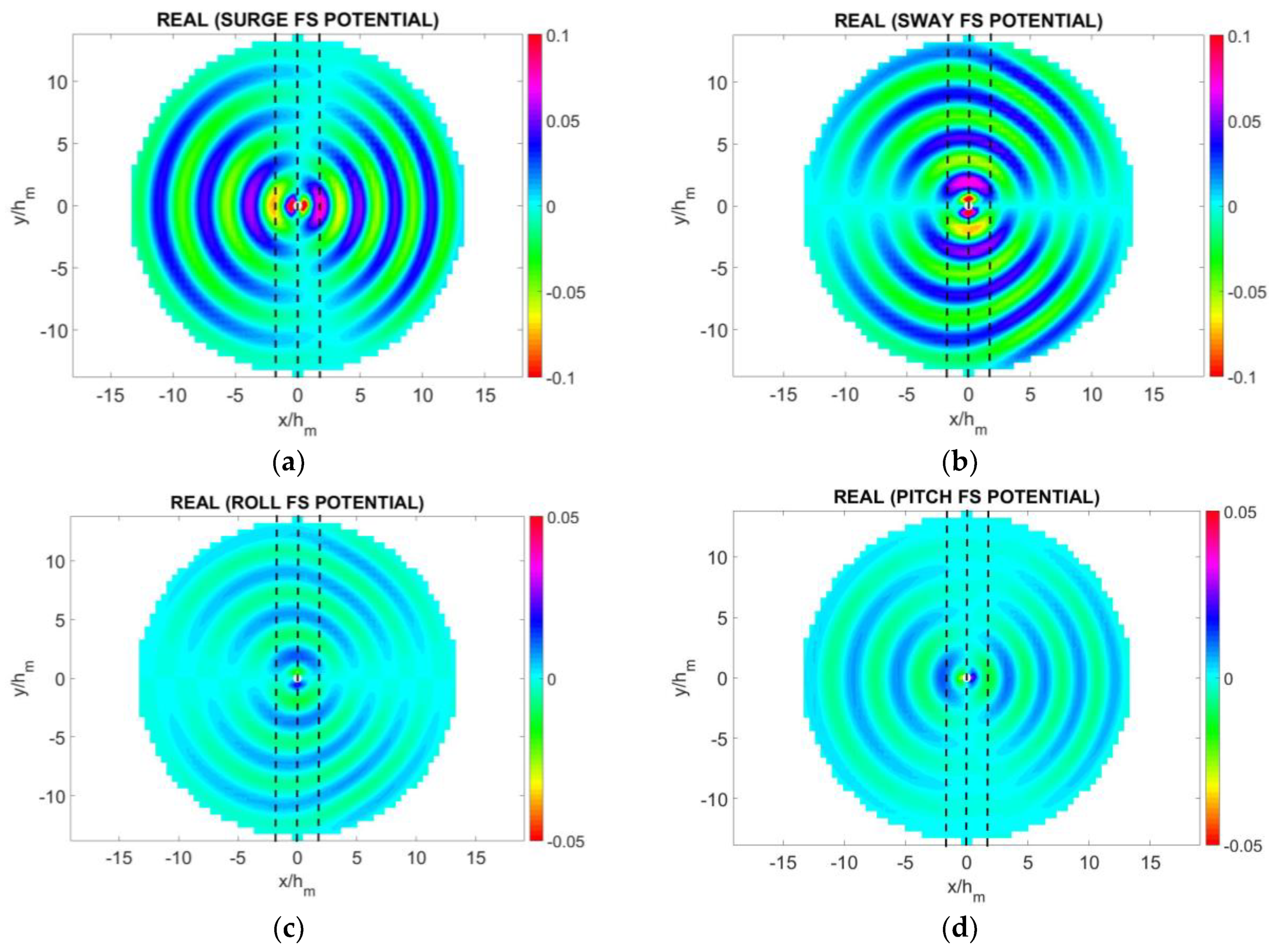
2.3. Diffraction and Radiation Potentials

The evaluation for the 3D diffraction and radiation potentials associated with the floating WEC will be treated by the BEM method developed by Belibassakis et al [21] and described in more detail in [13]. In this model, the induced potential and velocity from the collection of the 4-node quadrilateral elements, which are used to discretize all parts of the boundary surface (body, free-surface, seabed surface etc.), is given by
φ ( r ) = p F p Φ p ( r )
φ ( r ) = p F p U p ( r )
where the summation refers to all panels and Φp and Up denote, respectively, the induced potential and velocity from the pth element with unit singularity distribution to the field point r = ( x , y , z ) . The induced potential and velocities from each element are obtained by a semi-analytical method, and the discrete solution is finally obtained using the collocation method, used to satisfy the boundary conditions at the centroid of each panel of the geometrical configuration.

2.4. PML Implementation

The domain and the radiating behavior of the diffraction and radiation fields in the far field at large distances from the floating body are numerically simulated by means of an absorbing layer technique, based on a perfectly matched layer (PML) applied all around the borders of the free-surface computational domain; see, e.g., [22]. In the present model, the free-surface boundary condition is expressed by the following formula (see also [12,13,21]):
Φ n μ ( ω ) Φ = 0 , r D F
where
μ ( ω ) = { ω 2 g , R < R a ω 2 g ( 1 + i c ˜ ( R R a ) n λ n ) 2 , R R a }
The efficiency of the above technique to damp the outgoing waves with minimal back-scattering is dependent on various parameters of the present PML, including the layer thickness, its activation point R a , and the coefficient c ˜ . The latter are optimized by systematic investigation using as objective function the minimization of the error of the numerical solution against analytical results available in the case of floating vertical cylindrical bodies in constant depth; see, e.g., [23]. This procedure is evaluated in detail in [12], and is shown to provide satisfactory results proving the reliability of the present hybrid BEM-PML-CMS numerical scheme.

2.5. Mesh Generation

In computational hydrodynamic problems, mesh generation is an issue of utmost importance. From this perspective, in the present problem, every part of the boundary surface is discretized by distribution of the panels (4-node quadrilateral elements), satisfying perfect junction of various sub-meshes, and ensuring global continuity of geometry. A cylindrical arrangement of panels in all boundary parts is used, as shown in Figure 1, which is found to be suitable for the representation of the radiating behavior of the diffraction and radiation fields; see also [12]. In the example illustrated in Figure 1, the mesh resolution is: 10 × 88 for the cylindrical WEC (with the first index representing vertical and the second azimuthal discretization). A domain extent of 4 wavelengths on the free surface is discretized into (4N/λ) × 88 and 26 × 88 elements on the bottom surface, respectively, where N denotes the number of elements per wavelength for discetizing the domain. A finer mesh on the floating body corresponding to 18 × 88 elements is also used for examining the convergence of calculated results.

2.6. Variable Bathymetry

In this work, the effect of sloping seabeds on the WEC performance is examined by considering an operation over a smooth but steep shoaling region. The seabed profile exhibits a monotonic variation along the x-axis, described as follows
h ( x ) = h m 0.5 ( h 1 h 3 ) tanh ( α b o t π ( x x m e a n ) )
where the mean depth is: hm = 0.5(h1 + h3) and xmean is the center of the domain span along x-axis, where the WEC is also located. The coefficient αbot controls the bottom slope. The region is characterized by constant depths at infinity, in particular h1 and h2.

2.7. 2-DOF WEC Problem Formulation

The idea of combining more than one degree of freedom for harnessing the available power provided by the incident wave is another perspective on improving the WEC efficiency. In this case, the device is able to absorb a higher amount of incident wave power and presents improved grid stability [13,24,25,26]. Considering the floating WEC operating in two power modes, namely heaving and pitching with amplitudes ξ 30 , ξ 50 , respectively, the responses are obtained from the solution of the following system of coupled equations
D 33 ξ 30 + D 35 ξ 50 = X P 3 + X D 3
D 53 ξ 30 + D 55 ξ 50 = X P 5 + X D 5
where
D 33 = ( ω 2 ( M + A 33 ) + i ω ( B 33 + B S 3 ) + C 33 ) ,   D 35 = ( ω 2 ( A 35 + I 35 ) + i ω B 35 + C 35 )
D 53 = ( ω 2 ( A 53 + I 53 ) + i ω B 53 + C 53 ) ,   D 55 = ( ω 2 ( A 55 + I 55 ) + i ω ( B 55 + B S 5 ) + C 55 )
The hydrodynamic coefficients of added mass and damping, as well as the excitation Froude–Krylov and diffraction heave-forces and pitch-moments in the right-hand side of Equations (20) and (21), are calculated by the present BEM solver. As regards the rest of the included coefficients in the above expressions, the fact should be considered that the center of gravity is coincident to the center of the circular waterline of radius a. A typical mass distribution near the surface of the WEC is assumed, corresponding to radius of gyration Ryy = 0.7a and thus, I 55 = M R y y 2 . Also, C 33 = ρ g π a 2 , C 35 = C 53 = 0 , and C 55 = 0.25 ρ g π α 4 + M G B , where M denotes the mass of the body and GB the vertical distance between the center of buoyancy and the center of gravity. In the present work we have assumed a fixed location of CG coincident the center of buoyancy (GB = 0) for all WEC shapes examined (operating in one or more DOF) in order to provide a first comparative evaluation. It should be mentioned that, even in the latter case, substantial stability concerning the pitch motion is still offered by the available metacentric height. The latter in the case of the cylindrical WEC examined in the paper is 12% of the draft, while for the nailhead, WEC becomes 3.7 times the draft due to increased waterline area. Additional stability is offered by the PTO damping. Based on the above, in conjunction with the fact that in extreme cases a cut-off system is used to ensure safety, the simplified assumption GB = 0 is made and used for the examples considered here in order to illustrate the developed method to calculate the WEC performance and optimization. The consideration of variable mass distributions and different CGs would lead to a substantially more complicated multidimensional optimization problem that is left to be examined in future work. Finally, the coefficients D35 and D53 are found, for every geometry, to be quite small, compared with D33 and D55, and therefore the coupling between the two oscillatory modes is weak.

3. Design Assessment Features

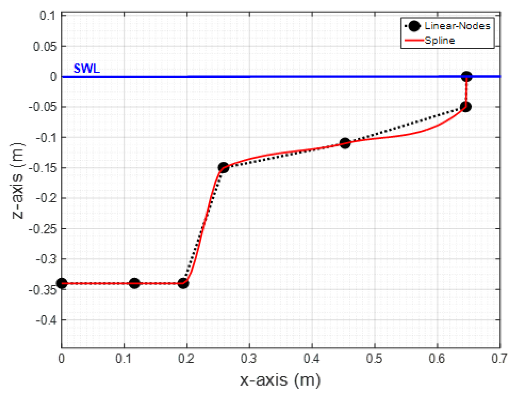
3.1. Geometries Generation

Many different WEC shapes are currently operating in coastal areas all over the world, used both for research purposes and commercial applications. Geometries like the conical, the semi-spherical, and the elliptical, as well as many other shapes, have been examined in a variety of studies (see, e.g., [27,28,29] and the references cited there). Based on the relevant industry trends and research activities, eight different axisymmetric body shapes have been examined. The geometrical details can be found in [12]. At this point, it should be mentioned that very sophisticated designs and shapes, which are normally accompanied with high R&D (research and development) and manufacturing costs, are not examined. The generation of the above shapes, as well as other axisymmetric geometries, is handled by a parametric model based on a spline representation of the profiles controlled by a set of nodes. As an example, the profile of the nailhead-shaped WEC is shown in Figure 2, and the body surface is obtained by 360 degrees rotation. One significant feature of the present WEC shape model is that it is in compliance with the constant-mass constraint. If the same material is considered for the construction of the considered point absorbers with the same mass distribution, then the radius and the draft of each shape can be calculated in order to maintain the submerged vertical cross section area equal to the area of the reference cylindrical WEC design corresponding to a/h = 1/3.5, T/a = 3/2, and d/h = 4/7, where a is the radius, T is the draft, h repreents the water depth, and consequently d = h-T is the bottom clearance below the WEC. For a more unbiased comparison between designs, the assumption of constant-mass is adopted as a basic reference feature for all the tested geometries.
The above parametric model could be exploited for directly finding the most efficient design. However, in order to reduce the computational cost, a particular set of variants was studied and specific details can be found in Reference [12].

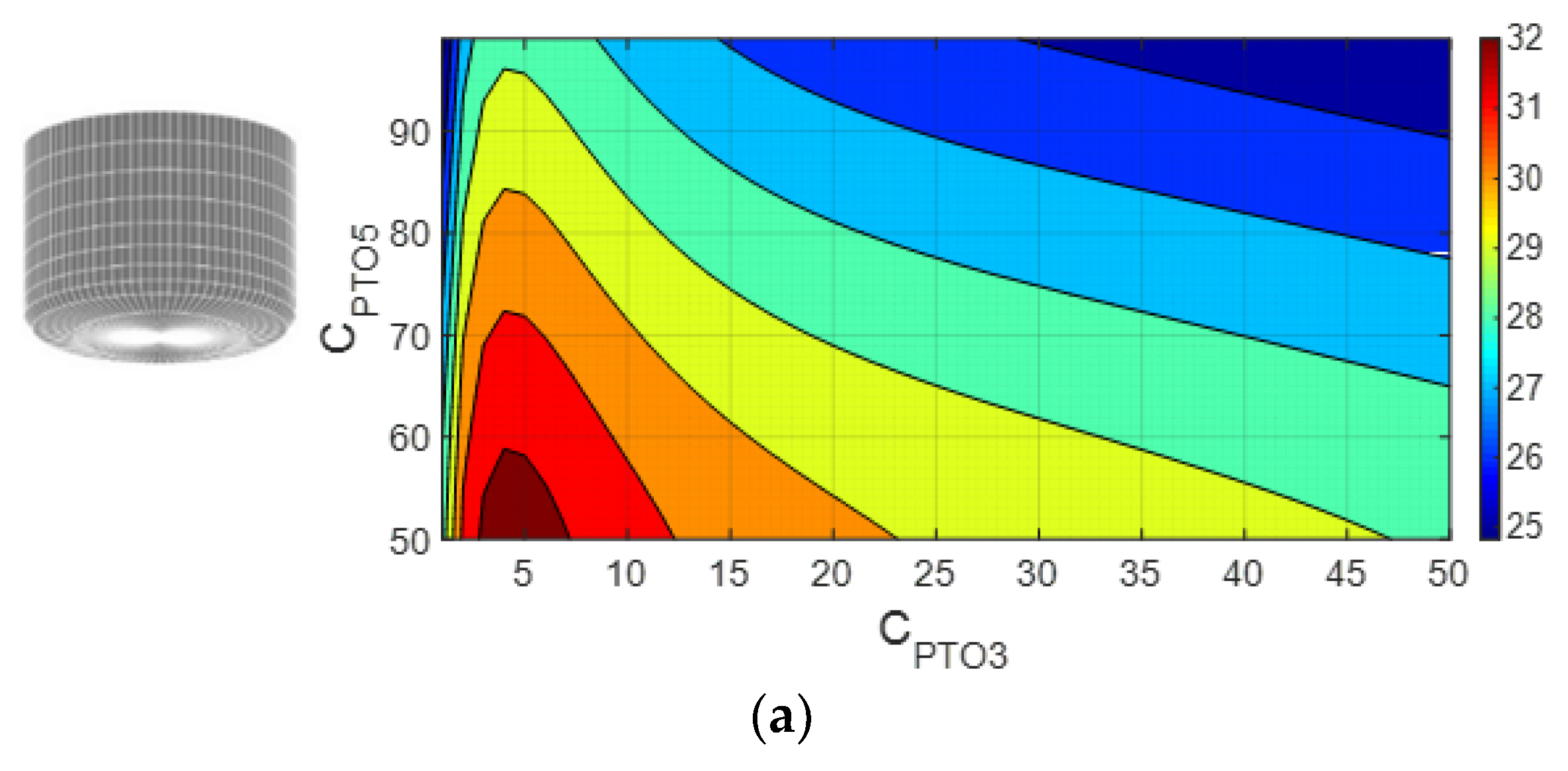
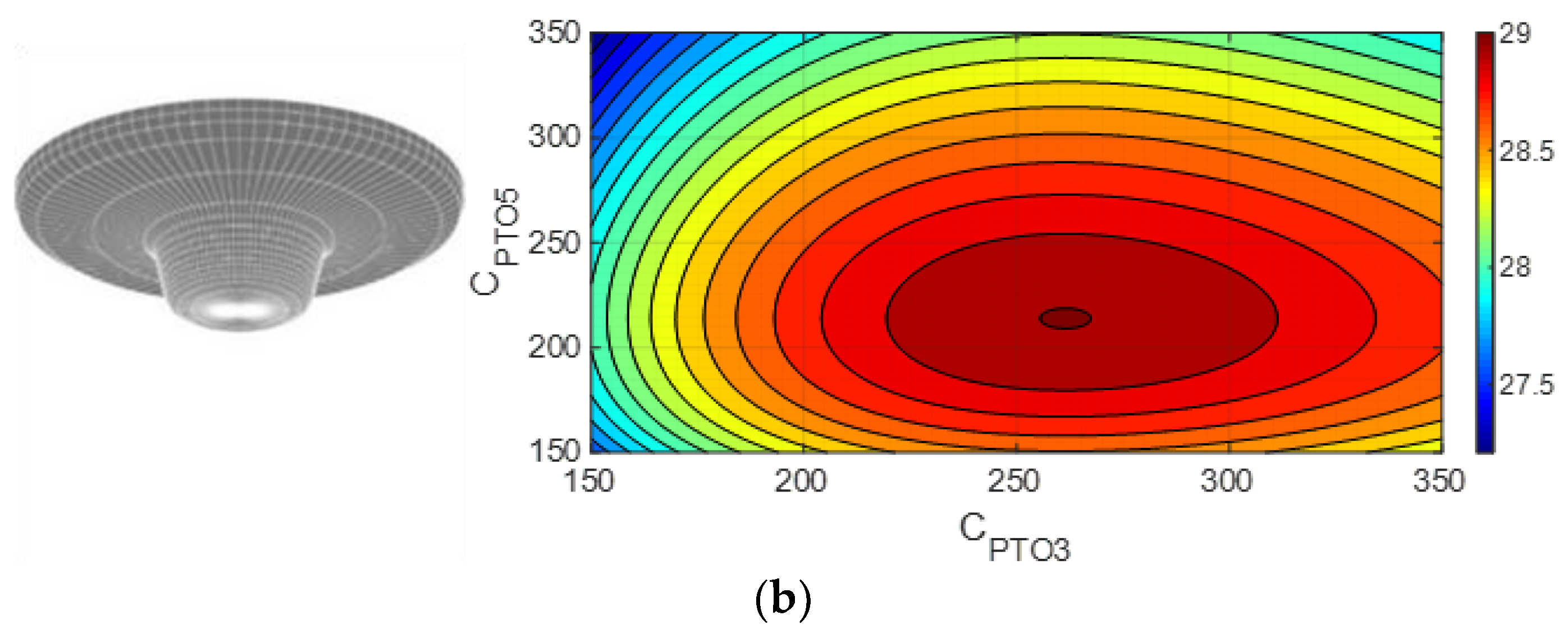
3.2. PTO Damping Configuration

For the evaluation of the absorbed power output by the devices, a typical PTO has been assumed. The heave-PTO coefficient B S 3 is taken CPTO3-times the mean value of hydrodynamic damping b ¯ 33 over the frequency range, B S 3 = C P T O 3 b ¯ 33 , which for the cylindrical WEC considered here is estimated as 2 π b ¯ 33 M ω R 3 = 0.12 , and the corresponding resonance frequency is ω R 3 a / g = 0.7 . A similar PTO assumption is considered for the pitch motion, where the PTO damping is taken CPTO5-times the mean value of hydrodynamic damping b ¯ 55 over frequency, which is estimated as 2 π b ¯ 55 M ω R 5 = 0.01 , where the corresponding resonance frequency is ω R 5 a / g = 0.45 . The values for the coefficients CPTO3 and CPTO5 are selected over a wide range, according to the geometry, contextually, and more detailed investigation of their operational restrictions. Very low values of the PTO coefficients, both for heave and pitch mode, are not considered either because they are incompatible with the current industry standards, or because they lead to high resonance amplitudes which are not permitted due to operational limits and survivability restrictions. These limits are decided after a careful examination of the relevant responses and performances. The damping coefficient of the power take off system is a decisive parameter for the performance of the devices, and after fine tuning and optimization is expected to provide significant improvements concerning the overall WEC performance.

3.3. Performance Index Definition

The averaged power-P output of the device, normalized with respect to the incident wave power, is plotted in Figure 3 in the case of the cylindrical-shaped WEC. According to the selection of PTO damping, there are cases of concentrated power maximization in the near-resonance frequency bandwidth, or cases of lower power levels, corresponding to responses covering wider frequency bandwidth. The curve with the largest area below defines the optimum PTO damping value. The latter behavior concerning the extraction of incident wave energy is exploited in the definition of an index quantifying the performance of different designs, which is based on the area below the "most-efficient-curve" of normalized power output. The result will be used, in normalized form with respect to incident power, to quantify the overall performance of the WEC and will be called performance index (PI%).
In more detail, each WEC design corresponds to a different waterline radius due to mass-constraint implementation. Therefore, the operational bandwidth of non-dimension angular frequency varies among the WECs. In order to obtain a reliable index for assessing their performance, the P.I. is defined as the ratio of the area below the power curve for the optimum PTO damping to the area of the rectangle [0,1] and [0.2, max ( ω a / g ) ], representing the total available power for absorption by the system. It should be considered that the fact for this rectangle is that the horizontal axis span differs to the efficiency frequency bandwidth, commonly used in WEC evaluations, a fact that can be observed with a closer look of Figure 3, where this difference is apparent. It should also not be overlooked that even if this index takes small values, almost insignificant compared with the capture width ratio (CWR) of WEC devices, however, as its definition explains, is a totally different index and every alteration of its value, caused for example by a variable-depth seafloor, is countable. For the extension of the latter definition to the 2-DOF WEC, the total power output, calculated as the summation of the contribution by each mode individually, will be used as the performance index.

4. Numerical Results and Discussion

4.1. Heaving Cylindrical WEC over Variable Bathymetry

The investigation of the heaving response of the reference cylindrical WEC over a variable seabed is discussed in this section. As an example, the cylindrical WEC with a/h = 1/3.5, T/a = 3/2, and d/h = 4/7 operates over a variable bottom topography described by Equation (19), with h1 = 1.5 m, h3 = 0.5 m, and αbot = 0.5. The propagation field, evaluated by the CMS, is illustrated in Figure 4 in the case of normally incident waves of frequency ω a / g = 0.7 (resonance frequency). The corresponding bathymetric non-dimensional frequency of the waves is ω h / g = 1.3 . It is clearly observed that the propagating field is diffracted and reflected, and the bottom boundary condition is consistently satisfied, by the fact that the equipotential lines intersect perpendicularly in the seabed profile. In Figure 4, the illustration of the free-surface elevation is also indicated by using solid black line.
Using the data concerning the propagating wave field and its normal derivative over the motionless WEC-scatterer, the diffraction field is calculated by the present BEM-PML solver which is illustrated in Figure 5, where the bottom contours are also plotted using dashed lines and the body’s position is indicated with the white disk in the center of the domain. The heave radiation field on the free surface for WEC frequency ω a / g = 0.7 over the variable bottom topography (h1 = 1.5 m, h3 = 0.5 m, αbot = 0.5), is shown in Figure 6 as calculated by the present method. The bottom contours are indicated by using dashed lines. Furthermore, the calculated radiation potentials related to the rest oscillation modes (except of yaw, which is not excited) are presented in Figure 7 for the same frequency as before. The details of the radiated wave pattern are clearly observed in these plots, as well as the effects of variable seabed topography, resulting in an amplification of wave amplitudes in the shallower region due to shoaling effects. The effectiveness of the present PML model is clear in these plots by noticing the damping of the outgoing waves after the PML-activation point, which in the cases considered is set at a radius of three wavelengths away from the floating body.

4.2. Heaving (1-DOF) WECs over Variable Bathymetry

In order to examine the effect of variable seabed topography on the WEC performance over shoaling bottom topography, the responses are evaluated for the eight different WEC shapes which have been presented and discussed in detail in Reference [12]. Except for the steep bottom profile considered in the previous section, a second less steep bathymetric profile was initially examined, which is also described by Equation (19), for h1 = 1.2 m, h3 = 0.8 m, and αbot = 0.5. Both seabed geometries have the same mean depth, hm = 1 m, but the maximum bottom slope decreases from 0.7 to 0.3.
The main aim of the present work is the assessment of the performance of the devices by means of the achieved performance index. The damping of the PTO is set initially, for the assessment of the designs, as: CPTO3 = [1, 5, 10, 50, 100, 250, 500, 750, 1000]. The latter configuration will be optimized in the sequel in order to estimate the value of the exact PTO damping coefficient providing the best performance. Numerical results concerning the performance index are presented in Table 1 for each WEC design over a flat bottom and variable bottom topography. We observe that the conical WEC is selected as the design with the best performance, among all the investigated alternative designs in the case of an 1-DOF device and this holds true for both of the examined depth configurations. Furthermore, comparison between the two most efficient shapes, i.e. the conical and the semi-spherical, is also performed in [28] and concludes again in the superiority of the conical WEC against the semi-spherical one.
Moreover, the shoaling sea bottom topography is shown to affect the performance of every WEC-design, and more specifically it causes an increase of the device’s ability for harnessing wave energy. The highest upgrade is detected for the disk-shaped WEC, being equal to almost +3.3%. However, it should be taken under consideration the fact that the performance index (P.I.) used in the present work to quantify the overall WEC performance, accounts for the whole frequency bandwidth and not only the efficient bandwidth of each WEC operation. For example, in the case of the cylindrical WEC, it is clearly observed in Figure 3 that the efficient bandwidth is 0.2 < ω a / g < 1 while the total bandwidth extends in the range 0 < ω a / g < 1.8 . The latter is used because the efficient frequency bandwidth of other WEC shapes is different but it is included in the extended range. The above has the effect that changes of the calculated PI due to bathymetry remain rather small.
Results like this are very promising and may be a first indication for installations of WECs over a deliberately sloping seabed, with man-made constructions and interventions that could be combined with water wave lenses producing the focusing of the wave energy in the location of the WEC or WEC-array and contributing to achieve higher power absorption by the devices. Further studies of this effect and optimization will be subjects of future work.
Proceeding to the determination of the optimal PTO damping values for the conical WEC, it is found by finer discretization of the parameters that a performance index of 17.95% is achieved for a PTO coefficient equal to CPTO3 = 77 in the case of the flat bottom. The latter index has further improved to 18.10% with CPTO3 = 80 over the smooth shoal, Equation (19). This result is more proof of the significance of the effects by a varying topography in the design-task of the WECs.

4.3. 2-DOF WECs over Variable Bathymetry

The accomplished performance index by the 1-DOF WEC design may be appreciably upgraded by considering the device operating in 2-DOFs (heave and pitch). These modes of operation are normally coupled with surge oscillation mode and all those three degrees of freedom determine the maximum possible energy absorption by a wave device, according to [4]. However, in this study, surge power mode is omitted, with the WEC assumed to be properly moored. Moreover, surge motion is strongly affected by more complex phenomena such as wave drift forces and thus this assumption is in compliance with the complexity of the developed hydrodynamic theory. The same procedure for the selection of the most efficient shape and the optimal PTO damping coefficient is followed, using the subsequent values of PTOs coefficients CPTO3 = [1, 5, 10, 20:10:340] and CPTO5 = [50:10:400], resulting in the data presented in Table 2.
In this case, the two qualified designs are the cylindrical WEC and the nailhead-shape WEC, which are expected to be the best performing designs in the case of heaving-pitching body due to its larger waterline area. The results summarizing the performance over flat and sloping seabed topography are listed in Table 3. It is observed that the effect induced by the variable seafloor is sometimes constructive, for example, as for the Disk-shaped device (+0.27%), and other times destructive, as it happens in the case of the cylindrical device (−0.43%).
As stated previously, the impact of the seabed profile is now not so simple and affects the performance of the device in a more complicated way. The PTOs used for harnessing power from the sea environment are exhibiting different damping values. Thus, the optimization of the PTO coefficients is investigated with respect to three principal design parameters: (i) the geometry of the WEC, (ii) the heave-PTO damping coefficient, and (iii) the pitch-PTO damping coefficient. The calculated values of the performance index for the cylindrical and the nailhead-shape WECs operating over a flat bottom topography are plotted in Figure 8, allowing the prompt comparison and the determination of the optimal PTO damping coefficients.
Finally, the bathymetry also affects the optimal values of PTO damping for each device, and this can be studied considering it as an additional design constraint. The effects on the WEC performances by the variable bathymetry in the case of the smooth shoal defined by Equation (19) are presented in Figure 9, with the strongest influence detected for the pitch power mode of the cylindrical WEC and the heave power mode of the nailhead-shaped WEC.

5. Sloping Seabed Effect

In order to better illusrate the effect of the sloping seabed on the performance of WECs, a second, steeper, bottom topography is considered, with bathymetric profile defined by Equation (19) for h1 = 1.5 m, h3 = 0.5 m, and αbot = 0.5; see Figure 4. The results, presented in Table 4 for the optimum heaving-WECs and 2-DOF WECs, prove that the effects by the seabottom cannot be predicted a priori. For the heaving WEC, a slight increase of PI is observed, while for the 2-DOF systems, an increase for the cylindrical WEC is obtained. The nailhead-shaped design performance index seems almost unaffected by the bottom topography. Again, the small changes of P.I. values are due to the bandwidth extent that has been considered for the definition of the index in order to enable comparison between various WEC shapes characterized by different resonant frequencies.

6. Conclusions

In the present work, several aspects related to the performance of wave energy converters of the type of point absorbers are studied, using a boundary element method for solving the associated hydrodynamic problems. In particular, a hybrid BEM coupled with a perfectly matched layer model is used for calculating the diffraction and radiation fields, based on information concerning the wave conditions around the floating bodies derived from a coupled mode model. The present method is shown to provide useful information, being able to treat general body geometry of the floating body operating in various oscillation modes over flat or sloping seabeds. Subsequently, it is systematically applied to numerically simulate the WEC performance in variable bathymetry regions. For the assessment and comparison of various designs, a specific performance index was defined as a useful indicator for the estimation of the power absorbing capacity. Regarding the PTO damping, which is exhibiting various constraints, this was found to be very important concerning the optimum performance of a WEC. From the results of the present study, it is concluded that the conical floater appears to be the most efficient design in the case of a heaving WEC, while the cylindrical and the nailhead-shaped forms are the ones exhibiting the highest performance operating as 2-DOF devices in coupled heaving and pitching modes. It is demonstrated that multiple DOF systems could substantially increase the levels of the extracted wave energy, and that the sloping seabed could also have an effect on the overall behavior of the devices and it should be taken into account. Future extensions of the present work include the examination of the performance and optimization of WEC arrays in more than two power modes in variable bathymetry, as well as the investigation of viscosity effects.

Author Contributions

The main idea of this work belongs to K.B. and M.B., while the main draft of the text and numerical simulations were handled by M.B.; E.R. participated in verification of the results, operated various corrections and acted as corresponding author. All authors agreed with the final form of this article.

Funding

The work of the corresponding author was carried out in the framework of the research project REMARC (Renewable Energy extraction in MARine environment and its Coastal impact), supported by the Romanian Executive Agency for Higher Education, Research, Development and Innovation Funding – UEFISCDI, grant number PN-III-P4-IDPCE-2016-0017.

Conflicts of Interest

The authors declare no conflict of interest.

Abbreviations

BCBoundary Condition
BEMBoundary Element Method
CMMCoupled-Mode Model
CMSCoupled-Mode System
DOFDegree Of Freedom
FSFree Surface
PIPerformance Index
PMLPerfectly Matched Layer
PTOPower Take Off
RAOResponse Amplitude Operator
R&DResearch & Development
SWANSimulating Waves Nearshore
SWLSea Water Level
WECWave Energy Converter

Nomenclature

aWaterline radius
AHydrodynamic matrix
abotBottom slope coefficient
aijAdded mass coefficient (i, j=1,…,6)
bijHydr. damping coefficient (i, j=1,…,6)
BmnCMS coefficient
BsPTO damping coefficient
cijHydrostatic coefficient (i, j=1,…,6)
CmnCMS coefficient
CPTOiPTO mean-damping multiplier
CsPTO hydrostatic coefficient
dBottom clearance
DijCoupling coefficient of i-j modes
FPSource strength of pth element
gGravity acceleration
GBCenter of buoyancy
HWave height
hDepth
iImaginary unit
MMass
NNumber of elements per wavelength
niNormal vector of i-mode (i=1,…,6)
PPower
P.I.Performance Index
RRadial distance
rPosition vector
RaPML activation radius
RyyRadius of gyration
tTime
TDraft
UPInduced velocity by pth element
xx-Coordinate
XDDiffraction excitation forces
XPFroude Krylov excitation forces
yy-Coordinate
zz-Coordinate
ZnVertical function of nth-mode (n=-1, 0, 1, …)
ΑmnCMS coefficient
ηFree surface elevation
ηeffPTO efficiency
λWavelength
μFrequency parameter
ξiResponse amplitude of i-mode (i=1,…,6)
ρWater density
ΦWave potential
φdDiffraction potential
φiRadiation potential of i-mode (i=1,…,6)
φnAmplitude of nth-mode (n=-1, 0, 1, …)
φpPropagation potential
ΦPInduced potential by pth element
φRRadiation potential
ωAngular frequency
ωRResonance angular frequency

References

  1. Al Shami, E.; Zhang, R.; Wang, X. Point Absorber Wave Energy Harvesters: A Review of Recent Developments. Energies 2019, 12, 47. [Google Scholar] [CrossRef]
  2. Wehausen, J.V. The Motion of Floating Bodies. Annu. Rev. Fluid Mech. 1971, 3, 237–268. [Google Scholar] [CrossRef]
  3. Mei, C.C. The Applied Dynamics of Ocean Surface Waves; World Scientific: Singapore, 1989. [Google Scholar]
  4. Falnes, J. Ocean Waves and Oscillating Systems: Linear Interactions including Wave Energy Extraction; Cambridge University Press: Cambridge, UK, 2004. [Google Scholar]
  5. Verao Fernandez, G.; Balitsky, P.; Stratigaki, V.; Troch, P. Coupling Methodology for Studying the Far Field Effects of Wave Energy Converter Arrays over a Varying Bathymetry. Energies 2018, 11, 2899. [Google Scholar] [CrossRef]
  6. Balitsky, P.; Quartier, N.; Verao Fernandez, G.; Stratigaki, V.; Troch, P. Analyzing the Near-Field Effects and the Power Production of an Array of Heaving Cylindrical WECs and OSWECs Using a Coupled Hydrodynamic-PTO Model. Energies 2018, 11, 3489. [Google Scholar] [CrossRef]
  7. Fernández, G.V.; Stratigaki, V.; Troch, P. Irregular Wave Validation of a Coupling Methodology for Numerical Modelling of Near and Far Field Effects of Wave Energy Converter Arrays. Energies 2019, 12, 538. [Google Scholar] [CrossRef]
  8. Charrayre, F.; Peyrard, C.; Benoit, M.; Babarit, A. A Coupled Methodology for Wave-Body Interactions at the Scale of a Farm of Wave Energy Converters Including Irregular Bathymetry. In Proceedings of the 33rd International Conference on Ocean, Offshore and Arctic Engineering (ASME 2014), San Francisco, CA, USA, 8–13 June 2014. [Google Scholar]
  9. McCallum, P.; Forehand, D.; Sykes, R. On the Performance of an Array of Floating Wave Energy Converters for Different Water Depths. In Proceedings of the 33rd International Conference on Ocean, Offshore and Arctic Engineering (ASME 2014), San Francisco, CA, USA, 8–13 June 2014. [Google Scholar]
  10. Massel, S.R. Extended refraction-diffraction equation for surface waves. Coast. Eng. 1993, 19, 97–126. [Google Scholar] [CrossRef]
  11. Touboul, J.; Rey, V. Bottom pressure distribution due to wave scattering near a submerged obstacle. J. Fluid Mech. 2012, 702, 444–459. [Google Scholar] [CrossRef]
  12. Belibassakis, K.; Bonovas, M.; Rusu, E. A Novel Method for Estimating Wave Energy Converter Performance in Variable Bathymetry Regions and Applications. Energies 2018, 11, 2092. [Google Scholar] [CrossRef]
  13. Bonovas, M. WECs over General Bathymetry: A Novel Approach for Performance Evaluation and Optimization. Master’s Thesis, National Technical University of Athens, Athens, Greece, 2019. [Google Scholar]
  14. Athanassoulis, G.A.; Belibassakis, K.A. A consistent coupled-mode theory for the propagation of small-amplitude water waves over variable bathymetry regions. J. Fluid Mech. 1999, 389, 275–301. [Google Scholar] [CrossRef] [Green Version]
  15. Belibassakis, K.A.; Athanassoulis, G.A.; Gerostathis, T.P. A coupled-mode model for the refraction-diffraction of linear waves over steep three-dimensional bathymetry. Appl. Ocean Res. 2001, 23, 319–336. [Google Scholar] [CrossRef]
  16. Belibassakis, K.A.; Gerosthathis, T.P.; Athanassoulis, G.A. A Coupled-Mode Model for the Transformation of Wave Systems Over Inhomogeneous Sea/Coastal Environment. In Proceedings of the 29th International Conference on Offshore Mechanics and Arctic Engineering (OMAE2010), Shanghai, China, 6–11 June 2010; pp. 471–478. [Google Scholar] [CrossRef]
  17. Berkhoff, J.C.W.; Booij, N.; Radder, A.C. Verification of numerical wave propagation models for simple harmonic linear water waves. Coast. Eng. 1982, 6, 255–279. [Google Scholar] [CrossRef]
  18. Vincent, C.L.; Briggs, M.J. Refraction–diffraction of irregular waves over a mound. J. Waterw. Port Coast. Ocean Eng. 1989, 115, 269–284. [Google Scholar] [CrossRef]
  19. Booij, N.; Ris, R.C.; Holthuijsen, L.H. A third-generation wave model for coastal regions: 1. Model description and validation. J. Geoph. Res. 1999, 104, 7649–7666. [Google Scholar] [CrossRef] [Green Version]
  20. Ryszard, M.S. Ocean Surface Waves: Their Physics and Prediction; World Scientific: Singapore, 1996. [Google Scholar]
  21. Belibassakis, K.A.; Gerostathis, T.P.; Athanassoulis, G.A. A 3D-BEM coupled-mode method for WEC arrays in variable bathymetry. In Progress in Renewable Energies Offshore, Proceedings of the 2nd International Conference on Renewable Energies Offshore (RENEW2016), Lisbon, Portugal, 24–26 October 2016; CRC Press: Boca Raton, FL, USA, 2016; p. 365. [Google Scholar]
  22. Turkel, E.; Yefet, A. Absorbing PML boundary layers for wave-like equations. Appl. Numer. Math. 1998, 27, 533–557. [Google Scholar] [CrossRef]
  23. Yeung, R. Added mass and damping of a vertical cylinder in finite depth waves. Appl. Ocean Res. 1981, 3, 119–133. [Google Scholar] [CrossRef]
  24. Brooke, J. Wave Energy Conversion; Elsevier Science: Amsterdam, The Netherlands, 2003. [Google Scholar]
  25. Davis, A.F.; Thomson, J.; Mundon, T.R.; Fabien, B.C. Modeling and Analysis of a Multi Degree of Freedom Point Absorber Wave Energy Converter. In Proceedings of the 33rd International Conference on Ocean, Offshore and Arctic Engineering (ASME 2014), San Francisco, CA, USA, 8–13 June 2014. [Google Scholar] [CrossRef]
  26. Sergiienko, N.Y. Three-Tether Wave Energy Converter: Hydrodynamic Modelling, Performance Assessment and Control. Ph.D. Thesis, University of Adelaide, Adelaide, Australia, 2018. [Google Scholar]
  27. Backer, G. Hydrodynamic Design Optimization of Wave Energy Converters Consisting of Heaving Point Absorbers. Ph.D. Thesis, University of Gent, Ghent, Belgium, 2009. [Google Scholar]
  28. Blommaert, C. Composite Floating Point Absorbers for Wave Energy Converters: Survivability Design, Production Method and Large-Scale Testing. Ph.D. Thesis, University of Gent, Ghent, Belgium, 2018. [Google Scholar]
  29. Franzitta, V.; Curto, D.; Rao, D.; Viola, A. Hydrogen Production from Sea Wave for Alternative Energy Vehicles for Public Transport in Trapani (Italy). Energies 2016, 9, 850. [Google Scholar] [CrossRef]
Figure 1. Computational meshes on (a) free surface, (b) bottom, and (c) WEC surface.
Energies 12 02108 g001
Figure 2. Generating spline of the nailhead-shaped WEC wetted surface.
Energies 12 02108 g002
Figure 3. Normalized power output by the reference cylindrical heaving WEC (a/h = 1/3.5, T/a = 3/2, d/h = 4/7) over the variable bottom (h1 = 1.2 m, h3 = 0.8 m, αbot = 0.5) for different PTO damping configurations. Indicative values of the C P T O 3 = B S 3 / b ¯ 33 considered here are C P T O 3 = [1, 5, 10, 20, 40, 80, 100].
Energies 12 02108 g003
Figure 4. Propagating field (real part) over a smooth shoal on the vertical plane as calculated by the CMS for normally incident waves ω h / g = 1.3 θ = 0 degrees. Variable bottom (h1 = 1.5 m, h3 = 0.5 m, αbot = 0.5).
Energies 12 02108 g004
Figure 5. Diffraction field (real part) on the free surface for normally incident waves ω a / g = 0.7 θ = 0 degrees as calculated by the present hybrid BEM over the variable bottom topography (h1 = 1.5 m, h3 = 0.5 m, αbot = 0.5). The bottom contours are indicated by using dashed lines.
Energies 12 02108 g005
Figure 6. Heave radiation field on the free surface for WEC frequency ω a / g = 0.7 over the variable bottom topography (h1 = 1.5 m, h3 = 0.5 m, αbot = 0.5), as calculated by the present method. The bottom contours are indicated by using dashed lines.
Energies 12 02108 g006
Figure 7. Radiation fields on the free surface for WEC frequency ω a / g = 0.7 over the variable bottom topography (h1 = 1.5 m, h3 = 0.5 m, αbot = 0.5), as calculated by the present method. (a) surge, (b) sway, (c) roll, (d) pitch.
Energies 12 02108 g007
Figure 8. Isoperformance curves of (a) Cylindrical WEC and (b) Nailhead-shaped WEC over flat bottom.
Energies 12 02108 g008aEnergies 12 02108 g008b
Figure 9. Normalized power output over flat and variable bottom topography (h1 = 1.2 m, h3 = 0.8 m, αbot = 0.5) using the optimized PTO. Cylindrical WEC in (a) heave mode and (b) pitch mode, and nailhead-shaped WEC in (c) heave mode and (d) pitch mode.
Energies 12 02108 g009
Table 1. 1-DOF WEC shapes and PI for flat and variable bottom topographies (h1 = 1.2 m, h3 = 0.8 m, αbot = 0.5).
WEC DesignMax {Performance Index}
Flat Bottom
Max {Performance Index}
Variable Bottom
Cylindrical11.29%11.41%
Nailhead-shaped15.38%15.74%
Disk-shaped13.66%14.11%
Elliptical14.73%15.11%
Egg-shaped10.63%10.82%
Conical17.70%17.92%
Floater-shaped9.87%10.10%
Semi-spherical13.30%13.39%
Table 2. 2-DOFs WEC shapes and PI for flat and variable bottom topographies (h1 = 1.2 m, h3 = 0.8 m, αbot = 0.5).
WEC DesignMax {Performance Index (Heave+Pitch)}
Flat Bottom
Max {Performance Index (Heave+Pitch)}
Variable Bottom
Cylindrical32.43%32.00%
Nailhead-shaped29.00%29.08%
Disk-shaped22.04%22.31%
Elliptical27.12%27.26%
Egg-shaped26.25%25.84%
Conical21.99%22.07%
Floater-shaped19.65%19.59%
Semi-spherical13.44%13.60%
Table 3. Optimum WEC designs, P.I., and PTO damping for flat and variable bottom topography in the case of smooth shoal (h1 = 1.2 m, h3 = 0.8m, αbot = 0.5).
Design & Performance Cylindrical WECNailhead-Shaped WEC
Max{Performance Index (Heave+Pitch)}Flat32.47%29.00%
Variable32.04%29.08%
PTO damping coefficient: [CPTO3, CPTO5]Flat[4, 50][261, 214]
Variable[4, 50][276, 213]
Table 4. Optimum WEC designs, P.I. over flat and sloping seabeds with increased steepness.
TypeGeometryP.I. % Flatδ P.I. % Steep vs Flatδ P.I. % Steep vs Variable
Heaving WECsCylindrical11.3%6.2%5.2%
Conical17.7%3.1%0.8%
2-DOF WECsCylindrical32.4%0.3%1.6%
Nailhead-shaped29.0%0.1%0.4%

