Article

Effect of Different Zigzag Channel Shapes of PCHEs on Heat Transfer Performance of Supercritical LNG

School of Energy and Power, Jiangsu University of Science and Technology, Zhenjiang 212000, China
*
Author to whom correspondence should be addressed.
Energies 2019, 12(11), 2085; https://doi.org/10.3390/en12112085
Submission received: 10 May 2019 / Revised: 25 May 2019 / Accepted: 30 May 2019 / Published: 31 May 2019
(This article belongs to the Collection Advances in Heat Transfer Enhancement)

Abstract

:
The channels of a printed circuit heat exchanger (PCHE) can have different shapes, and the zigzag channel shape is one of the most widely used because of the relatively simple manufacturing process and low cost. However, the heat transfer enhancement of a zigzag channel is at the expense of increasing the pressure drop. In this paper, new channel shapes of a PCHE, i.e., a zigzag with an inserted straight channel and a zigzag channel with radian, were numerically investigated, with the aim of improving the heat transfer and reducing the pressure drop of supercritical LNG using the SST κ-ω model. The local and total pressure drop and heat transfer performance of supercritical LNG in a zigzag channel, zigzags with 1–5 mm inserted straight channels, and a zigzag channel with radian were analyzed by varying the mass flow rate from 1.83 × 10⁻⁴ to 5.49 × 10⁻⁴ kg/s. Performance evaluation criteria (PEC) were applied to compare the overall heat transfer performance of the zigzags with 1–5 mm inserted straight channels and a zigzag channel with radian to the zigzag channel of a PCHE. The maximum pressure drop for the zigzag channel was twice the minimum pressure drop for the zigzag channel with radian, while the convective heat transfer coefficient of the zigzag with a 4 mm inserted straight channel was higher, which was 1.2 times that of the zigzag channel with radian with the smallest convective heat transfer coefficient. The maximum value of the PEC with 1.099 occurred at a mass flow rate of 1.83 × 10⁻⁴ kg/s for the zigzag with a 4 mm inserted straight channel, while the minimum value of the PEC with 1.021 occurred at a mass flow rate of 5.49 × 10⁻⁴ kg/s for the zigzag with a 1 mm inserted straight channel. The zigzag with a 4 mm inserted straight channel had the best performance, as it had a higher PEC value at lower mass flow rates.

1. Introduction

Due to the technology of photochemical etching for the channel and the diffusion bonding for the stacking of plates, the channel size of the printed circuit heat exchanger (PCHE) is reduced to 1–3 mm resulting in PCHEs being very compact with a large heat transfer area and low temperature and high pressure bearing capacity [1,2,3]. Due to these advantages, PCHEs are suitable in volume-limited applications, such as a vaporizer [4].
PCHEs can have two types of channel—continuous and discontinuous structures. The continuous channel type includes the straight channel, zigzag channel, and wave channel, and the discontinuous channel consists of noncontinuous S-shaped and airfoil fins [5]. Chen et al. [6] numerically studied the steady-state and transient thermal performance using helium in a straight channel PCHE and experimentally verified the applicability of the dynamic model of the PCHE for simulating its performance. Mylavarapu et al. [7] investigated both numerically and experimentally the straight channel PCHE. The experimental heat transfer and pressure drop data were compared with the available models and correlations. The pressure drop and Fanning friction factor were obtained at laminar and laminar-to-turbulent transition flow regimes numerically. Chen et al. [8] studied numerically and experimentally a zigzag PCHE using helium as the working fluid. The dynamic response of the PCHE was analyzed, and transient tests were experimentally carried out. The comparison between the simulation and experimental data proved the reliability of the dynamic model. Zheng et al. [9] studied transient heat transfer in a semicircular zigzag channel at laminar flow with Reynolds numbers (Re) of 400–800 and Prandtl numbers of 0.7–20. They found that both the heat transfer enhancement and the pressure drop rise as the Re increases, and the enhancement of the heat transfer is inversely proportional to Pr1/3. Lee et al. [10] used three-dimensional RANS analysis and a hybrid multiobjective evolutionary algorithm coupled with the RSA model to optimize the zigzag channel of a PCHE to enhance the heat exchange effectiveness and reduce frictional loss. Kim et al. [11] developed the Fanning factor and Nusselt number correlations by considering the parameters that significantly affect the thermal hydraulic performance of a PCHE, such as angle, pitch, and hydraulic diameter. Yang et al. [12] numerically investigated a wavy channel PCHE, studied the effect of narrowing channel cross-sections on the thermal hydraulic performance, and proposed new heat transfer and frictional factor empirical correlations. Tsuzuki et al. [13] numerically investigated the effect of the fin angle, overlapping length, fin width, fin length, and edge roundness of S-shaped fins on the thermal hydraulic characteristics of a microchannel heat exchanger. Chu et al. [14] ran a numerical simulation of the airfoil fins’ geometrical structure. They analyzed the dynamic performance and heat transfer characteristics with different pitches and fitted the correlations of j and f factors.
Based on previous research, considering the manufacturing process and the cost, the zigzag channel has been widely used in PCHEs [3,5,11]. However, the heat transfer of zigzag channels is 1.2 times and the pressure drop is 1.5 times that of straight channels [15]. The increase in heat transfer capacity is accompanied by a larger increase in pressure drop. Therefore, it is necessary to decrease the zigzag channel’s pressure drop performance and improve its heat transfer performance.
At present, there are two ways to increase the heat transfer performance and decrease the pressure drop. One way is to optimize the structure; the other is to replace the traditional fluid with a supercritical fluid [16,17]. Several studies have used carbon dioxide and helium on PCHEs as the working fluid [18,19,20]. However, supercritical CO2 is considered as the working fluid in the Brayton cycle for high temperature gas-cooled reactors (HTGRs) because of its high density, low viscosity, and high thermal conductivity [5,21,22], while only a few studies using supercritical LNG on a PCHE vaporizer exist [16].
In our previous work [23], the influence of a zigzag channel’s bending angles in a PCHE on the heat transfer performance of supercritical LNG was numerically investigated, and the study found that the heat transfer and the pressure drop of supercritical LNG were highest at a bending angle of 45°. The present paper, based on the zigzag channel with a bending angle of 45°, proposes new types of channels in a PCHE, i.e., a zigzag with an inserted straight channel and a zigzag channel with radian, to improve the heat transfer and reduce the pressure drop. Numerical analysis on the local and overall heat transfer performance and pressure drop for the zigzag, zigzags with 1–5 mm inserted straight channels, and the zigzag channel with radian was carried out within the range of 1.83 × 10⁻⁴ to 5.49 × 10⁻⁴ kg/s mass flow rate. To find the channel structure with the best heat transfer performance, comprehensive consideration of the heat transfer performance and pressure drop was made, and performance evaluation criteria (PEC) were proposed to compare the heat transfer performance of zigzags with different lengths of inserted straight channels and the zigzag channel with radian to the zigzag channel.

2. Numerical Methodology

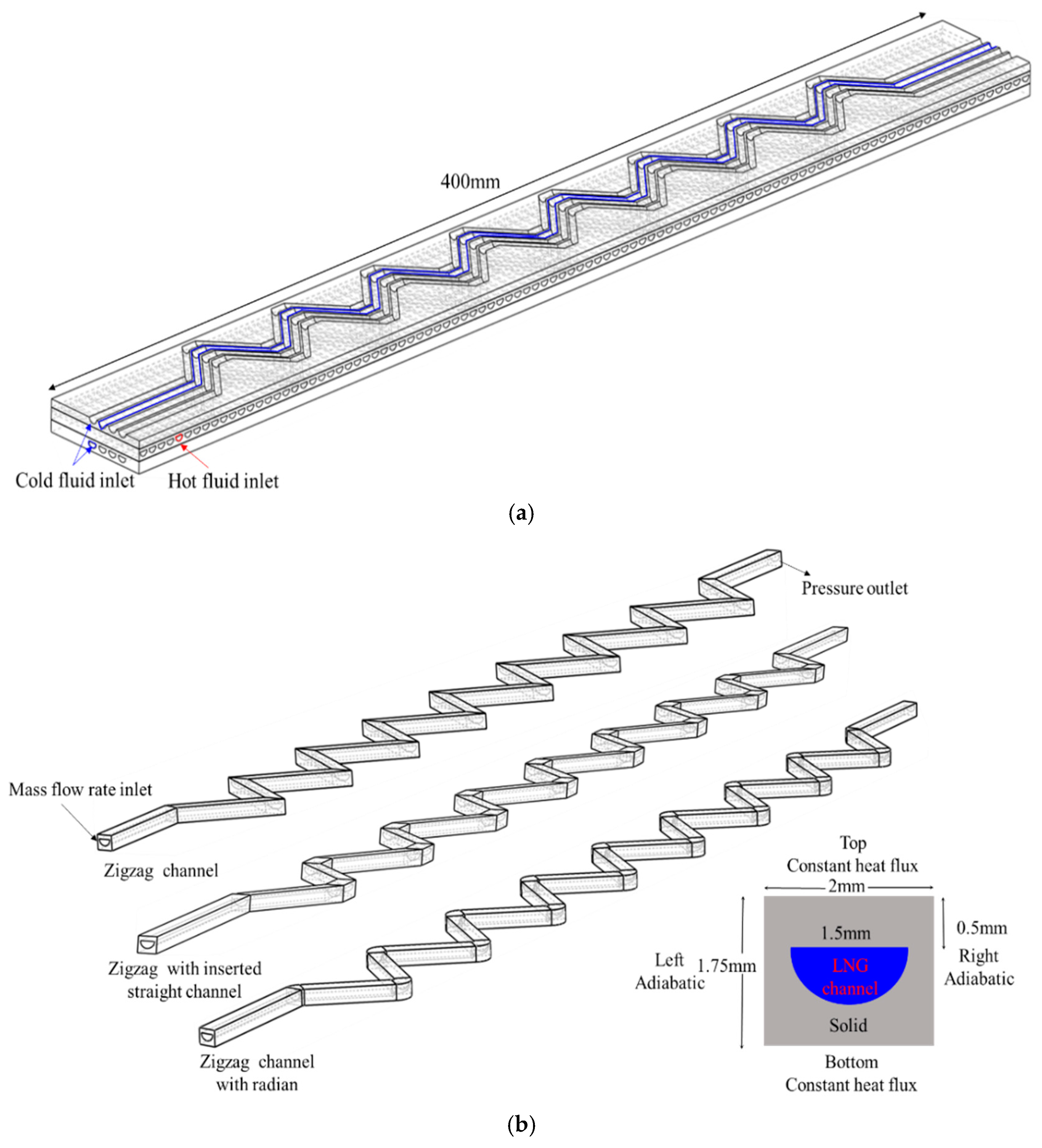
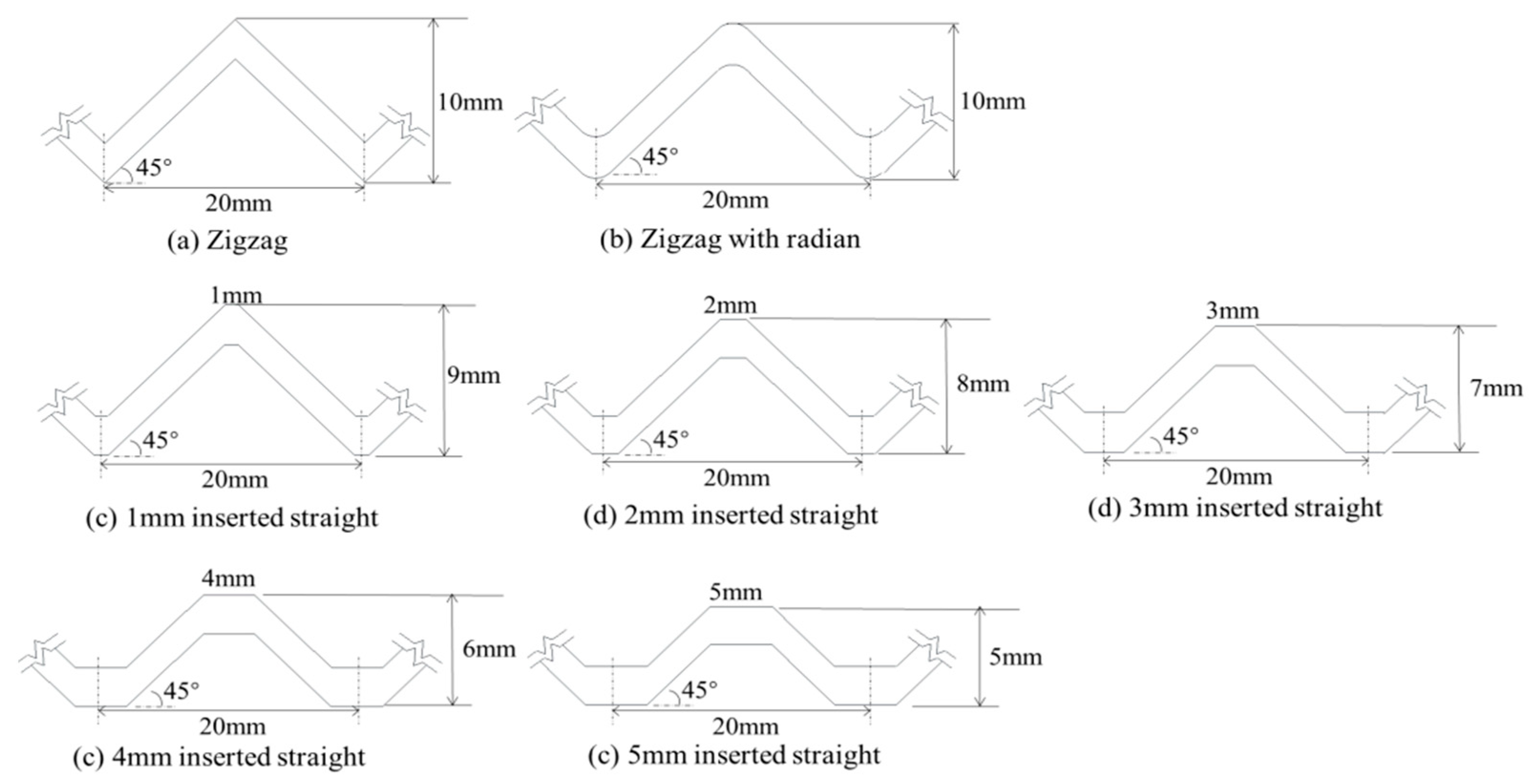
2.1. Physical Description

This study numerically investigated the thermal hydraulic performance of LNG in three different geometries of the cold channel in a cross flow PCHE. Figure 1a shows the straight hot channel with R22 as a working fluid to eliminate the risk of freezing [24] and the cold channel with the supercritical LNG single banked in the cross-flow arrangement. The investigated structures of the cold channel were zigzag, zigzag with an inserted straight channel, and zigzag channel with radian. Since it is impossible to simulate the fluid flow in the whole PCHE, and with the supercritical LNG in the cold channel being investigated, the model needed to be simplified. The mass flow rate of each cold channel was assumed to be the same and that it was adiabatic between two adjacent cold channels. Therefore, the model was reduced to a cold channel (Figure 1b). The solid part was made of steel, with a 2 × 1.75 mm section, and the diameter of the semicircular cold channel was 1.5 mm. A channel of 400 mm was divided into 20 pitches along the flow direction with 20 mm as the unit, and each pitch was expressed by Np. Figure 2 shows the geometric size of the three channel shapes; the bending angles of all the channels were designed to be 45°.
Figure 1b shows the model’s boundary conditions. The mass flow rate was set to be the inlet boundary condition, and the outlet boundary condition was set by the pressure outlet. A constant heat flux boundary condition was applied to the top and bottom walls, while the left and right walls were the adiabatic boundary condition. Table 1 summarizes the information for the boundary conditions.

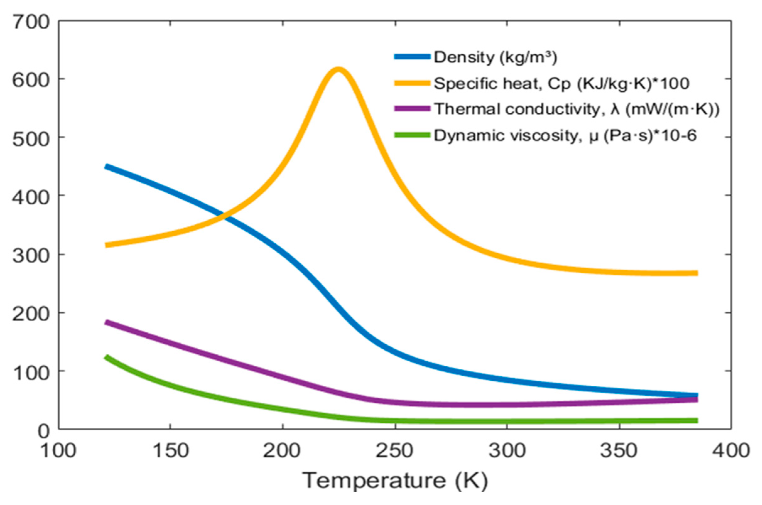
2.2. Thermo-Physical Properties of Supercritical LNG

Compared with conventional fluids, the temperature affects the thermal physical properties of supercritical LNG significantly, and some special changes occur. Figure 3 shows the changes in density, specific heat, thermal conductivity, and dynamic viscosity with temperature from 121 K to 385 K at 10 MPa. Near the pseudo-critical temperature, the thermal physical properties vary severely. The thermal physical properties of supercritical LNG are referenced from the NIST Standard Reference Database (REFPROP) [25]. Since the properties vary dramatically as the temperature changes, the values were fitted as a piecewise-polynomial function of temperature, and the function was then associated with the ANSYS Fluent.

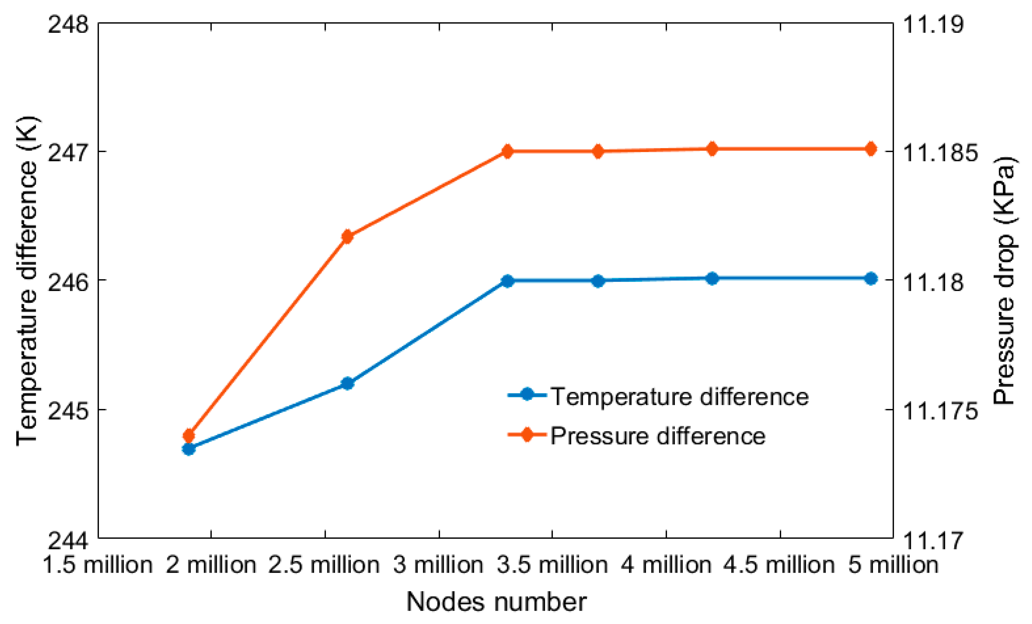
2.3. Numerical Method and Grid Independence

Commercial software ANSYS Fluent 14.5 was used for establishing the numerical model and run the simulation. The range of the average Re number was 7600–10,133, which was the turbulent flow condition. According to our previous work [23], the SST κ-ω model was chosen to calculate the supercritical fluids. The details of the SST κ-ω model are shown in the literature [26]. The coupling of velocity and pressure was set up by using the SIMPLE algorithm, because the error between the simulation results calculated by the SIMPLE algorithm and the experimental results was smaller than in other algorithms, and the second-order upwind scheme was applied to discretize the momentum, energy, turbulent kinetic energy, and turbulent dissipation rate equations. In addition, the calculations were considered to be convergent when the residual values were of 10−6.
The following governing equations of continuity, momentum, and energy were used in the calculation:
Continuity equation:
x i ( ρ u i ) = 0 ,
Momentum equation:
x i ( ρ u i u j ) = p x i + ρ g i + x j [ ( μ + μ t ) u i x j ] ,
Energy equation:
x i ( u i ( ρ E + p ) ) = x i ( k e f f T x i + u i τ i j ) ,
k e f f = k + k t
where ρ is density, ui is the velocity vector, p is pressure, µ and µt are the molecular and turbulent viscosities, respectively, keff is effective conductivity, and kt is turbulent thermal conductivity.
The local performance of heat transfer and the pressure drop are listed as follows:
Δ P = P o u t P i n ,
h = q T w T b = q T w ( T o u t + T i n ) / 2 ,
where Pout and Pin are the average pressure of the inlet and outlet, respectively, q is the constant heat flux, Tw and Tb are the wall temperature and average temperature, respectively, of the LNG at the inlet and the outlet.
N u = Nusselt number = h D h λ ,
D h = Hydraulic diameter = 4 A / l ,
f = Fanning friction coefficient = Δ P f D h 2 L ρ b v b 2 ,
Δ P f = Δ P Δ P a = Δ P ( ρ o u t v o u t 2 ρ i n v i n 2 )
where λ is thermal conductivity, A and l are the cross-sectional area and circumference of the semicircular fluid area, respectively, ΔPf and ΔPa are the frictional and accelerated pressure drops, L is the channel length, and ρ b and v b are the bulk density and velocity of the LNG, respectively.
The total Nusselt number (Nu) and Fanning friction coefficient are calculated as follows:
N u t = 1 n i n N u i ,
f t = 1 n i n f i ,
where N u i and f i are the average Nusselt number and Fanning friction coefficient of each channel pitch, respectively, and n is the number of the channel pitch.
The performance evaluation criteria (PEC) are defined as in Equation (12):
PEC = N u t , i N u t , z i g z a g ( f t , i f t , z i g z a g ) 1 3 ,
where the subscript t,zigzag is the total performance of the zigzag channel and t,i is the total performance of the other channel shapes.
The structured meshes for the model were generated by GAMBIT. For the semicircular fluid domain, the distance between the first layer and the interface was 0.01 mm, and the growth factor was set to 1.1 mm for the remaining rows. A grid independence study was performed for the zigzag channel. Figure 4 compares the influence of the size of the grid (i.e., 1.9, 2.6, 3.3, 3.7, 4.2, and 4.9 million nodes) on the temperature difference and pressure drop between the inlet and the outlet. When the number of nodes was greater than 3.9 million, the temperature difference and pressure drop barely changed. Hence, the mesh with 3.9 million nodes was selected.

2.4. Model Validation

In order to ensure the correctness of the simulation models and methods, the numerical results were compared to Zhao et al.’s experimental results [4]. A 520 mm long straight channel model with supercritical nitrogen as the working fluid was established, which was consistent with the experiment. In the simulation, the operating conditions, such as inlet temperature, inlet pressure, and mass flow rate of 102 K, 10 MPa, and 1.83 × 10⁻⁴ kg/s, respectively, were the same as the experimental conditions. Table 2 compares the experimental results with the simulation results and highlights that the relative error in temperature difference was 0.11% while the pressure drop was 3.82%, indicating that the numerical model and methods are applicable.

3. Results and Discussion

Figure 5 shows the local pressure drop performance of different channel shapes; the pressure drop was highest for the zigzag channel (11.85 kPa). The pressure drops for the zigzag channels with inserted straight channels from 1 to 5 mm were 7.9, 7.1, 6.9, 6.7, and 6.5 kPa, respectively, while that for the zigzag channel with radian was the lowest (5.9 kPa). The pressure drop of the zigzag channel was 33–60% larger than the other channel shapes. For the zigzag with the inserted straight channel, the pressure drop decreased as the length of the inserted straight channel rose. This phenomenon can be explained as follows: (1) The velocity of LNG in the zigzag channel was significantly higher than that of the other channel shapes (Figure 6), which increased the pressure drop of the zigzag channel. (2) The flow separation and dead zones occurring in the channel led to an increase in the pressure drop. The dead zones of the zigzag channel were larger than the other channels. (3) The longer the path of the LNG flow through the channel, the greater the pressure drop. Compared to the other shapes, the LNG had the longest flow path and the greater pressure drop in the zigzag channel. For the zigzags with the inserted straight channels, although Figure 6 shows that the area of the dead zone increased as the inserted straight channel length increased, the LNG flowing path decreased as the inserted straight channel length increased. (4) The pressure drop was the minimum in the zigzag channel with radian. Due to the small dead zone in the channel, the velocity gradient and the disturbance of LNG were small, resulting in a small pressure drop.
Figure 7 shows the local convection heat transfer coefficient along the flow direction for different channel shapes. The convection heat transfer coefficient was the highest for the zigzag with the inserted straight channel, especially after Np = 8. Moreover, the zigzag with the 1 mm inserted straight channel had the highest convection heat transfer coefficient. The channel with radian had a relative low convection heat transfer coefficient compared to the other channel shapes, maybe because the flow separation and the dead zone in the channel led to a reduction in the effective heat transfer area, resulting in a reduced heat transfer capacity. In Figure 6, the flow separation and the dead zone of the zigzag with a 1 mm inserted straight channel is not obvious, on the contrary, the dead zone in the zigzag channel appears before and after the bending point. The dead area in the zigzag channel is the largest, and it is the smallest in the zigzag with the 1 mm inserted straight channel. With the increasing length of the straight channel, the dead area increases. The dead zone is similar in the zigzags with the 3, 4, and 5 mm inserted straight channels. The zigzag channel with radian had a lower convection heat transfer coefficient than the other channel shapes. Although the dead zone was not obvious in the zigzag channel with radian, the velocity gradient was also small, proving that the geometry influenced the fluid a little, leading to the reduction of the convection heat transfer coefficient in the zigzag channel with radian.
According to Equation (5), the convection heat transfer coefficient is inversely proportional to the difference between the wall temperature and the fluid bulk temperature. Figure 8 shows the wall temperature and the LNG bulk temperature for the different channel shapes. After Np = 8, the growth rate of the wall temperature is greater than the LNG bulk temperature for the zigzag channel and zigzag channel with radian; therefore, they both have a much smaller convection heat transfer coefficient.
Figure 9 shows the Nusselt number (Nu) along the flow direction for the different channel shapes. The Nu increases and then reduces along the flow direction, because it is inversely proportional to the thermal conductivity. With the rising temperature of the LNG along the flow direction, the thermal conductivity declines sharply and reaches the minimum near the pseudo-critical temperature, then rises slightly (see the purple line in Figure 3). In addition, the Nu of the zigzag channel and zigzag channel with radian reaches the maximum value near Np = 12, while that of the zigzags with inserted straight channels peaks at Np = 16. This difference is due to the LNG temperature of the zigzag channel and zigzag channel with radian rising faster and reaching the pseudo-critical temperature at Np = 12, while the LNG temperature of the zigzags with inserted straight channels rises slowly and reaches the pseudo-critical temperature at Np = 16 (Figure 8b).
Figure 10 shows the average convection heat transfer coefficient of different channel shapes at different mass flow rates. The average convection heat transfer coefficient was the highest in the zigzags with the inserted straight channels, while it was the lowest in the zigzag channel with radian. As the mass flow rate rose from 1.83 × 10⁻⁴ to 5.49 × 10⁻⁴ kg/s, the average convection heat transfer coefficient of the different channel shapes increased due to the increase in turbulence. Figure 11 shows the trend of the Nusselt number of the different channel shapes when varying the mass flow rate: Nu increases and then decreases with the increase of the mass flow rate.
The Nusselt number at 2.745 × 10⁻⁴ kg/s was the maximum in all channel shapes, because as the mass flow rate increased, the heat absorbed by the fluid per unit volume from the solid decreased, resulting in a decrease of temperature, an increase of thermal conductivity, and a decrease of the Nu. The zigzags with the inserted straight channels had the largest average convection heat transfer coefficient, but the zigzag channel had a larger Nusselt number than the zigzags with the inserted straight channels. The temperature of the LNG was higher in the zigzag channel than that of the zigzags with the inserted straight channels, so the thermal conductivity was small, causing the Nu to become larger.
Figure 12 shows the total pressure drop, which was largest in the zigzag channel, whereas it was smallest in the zigzag channel with radian. The total pressure drop decreased as the inserted straight channel length increased. The pressure drop of the different channel shapes increased with the increase of the mass flow rate because of the rising velocity, as in Figure 13. Figure 14 shows the Fanning friction factor of the different channel shapes when varying the mass flow rate. The zigzag channel and the zigzag channel with radian had the largest and smallest Fanning friction coefficient, respectively. With the increasing length of the inserted straight channel, the Fanning friction coefficient decreased; also, the 3, 4, and 5 mm inserted straight channels had a similar Fanning friction coefficient. The Fanning friction coefficient reduced slightly as the mass flow rate increased. From Equation (8), the Fanning friction coefficient is inversely proportional to ρ b v b 2 . According to Figure 3, as the mass flow rate increases, the LNG temperature decreases, and the density and viscosity increase. The increased velocity and density lead to the increase in ρ b v b 2 , resulting in a reduction in the Fanning friction coefficient.
In order to compare the comprehensive heat transfer performance of the different channel shapes, performance evaluation criteria (PEC) were proposed to evaluate the heat transfer performance and pressure drop performance of the different channel shapes. Figure 15 shows the PEC for the zigzags with the inserted straight channels and the zigzag channel with radian. The PEC were all greater than 1, indicating that the comprehensive heat transfer performance of the LNG in these channels was better than the traditional zigzag channel. The PEC were higher at a lower mass flow rate. The maximum value of the PEC corresponds to a mass flow rate of 1.83 × 10⁻⁴ kg/s for the zigzags with the 4 and 5 mm inserted straight channels, while the minimum corresponds to the mass flow rate of 5.49 × 10⁻⁴ kg/s for the zigzag with the 1 mm inserted straight channel. The maximum and minimum values were 1.099 and 1.021, respectively. In summary, the results show that the zigzags with the inserted straight channels and the zigzag channel with radian had the best performance, which had higher PEC at lower mass flow rates. The zigzag with the 4 mm inserted straight channel had the greatest heat transfer performance.

4. Conclusions

In this study, the heat transfer and pressure drop performance of supercritical LNG in the zigzag channel, zigzags with inserted straight channels, and the zigzag channel with radian were discussed. Performance evaluation criteria were introduced to combine the heat transfer and pressure drop performance in order to compare the heat transfer performance of three different types of channel shape. Based on the results above, the following conclusions can be drawn:
(1)
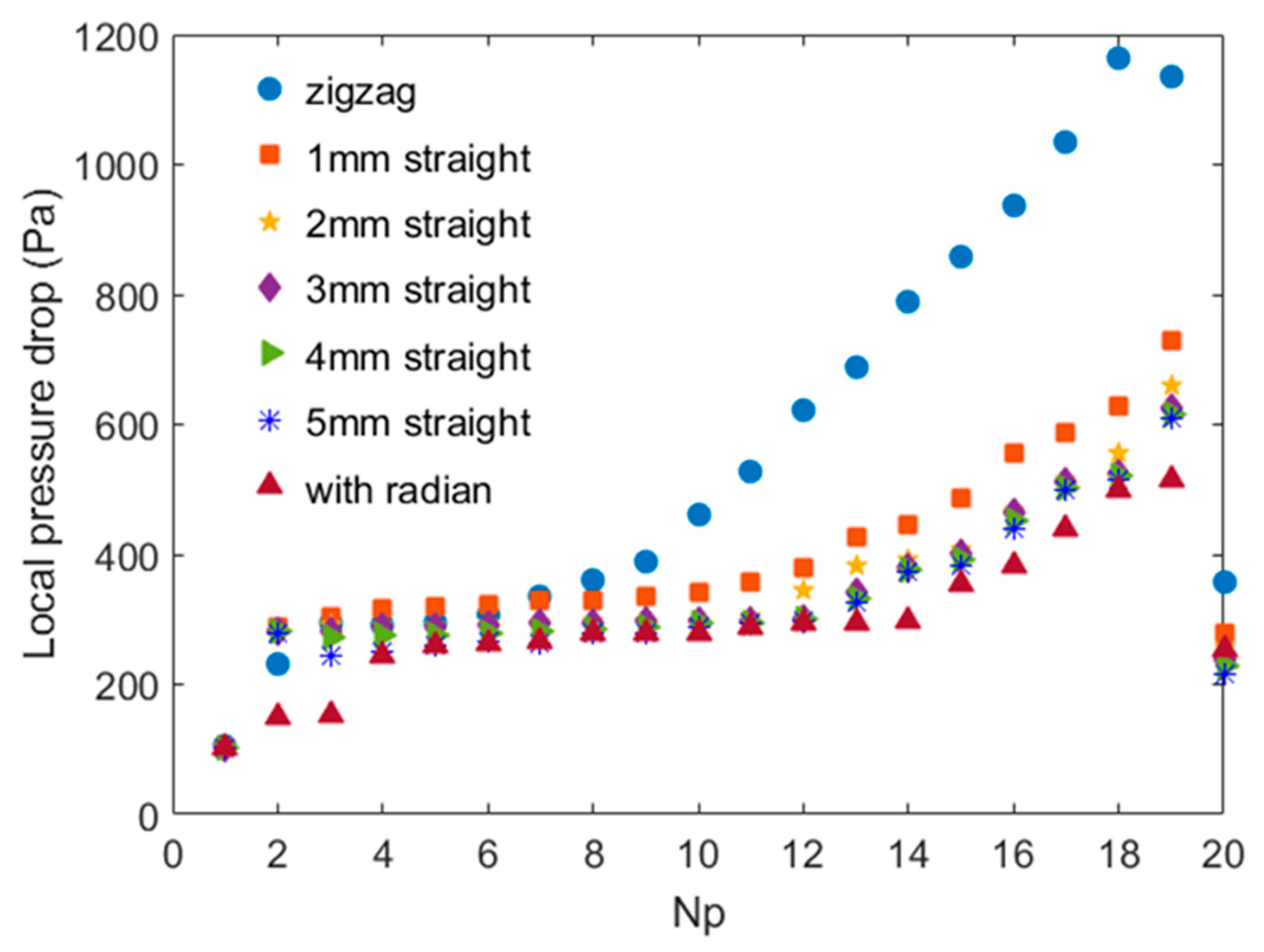
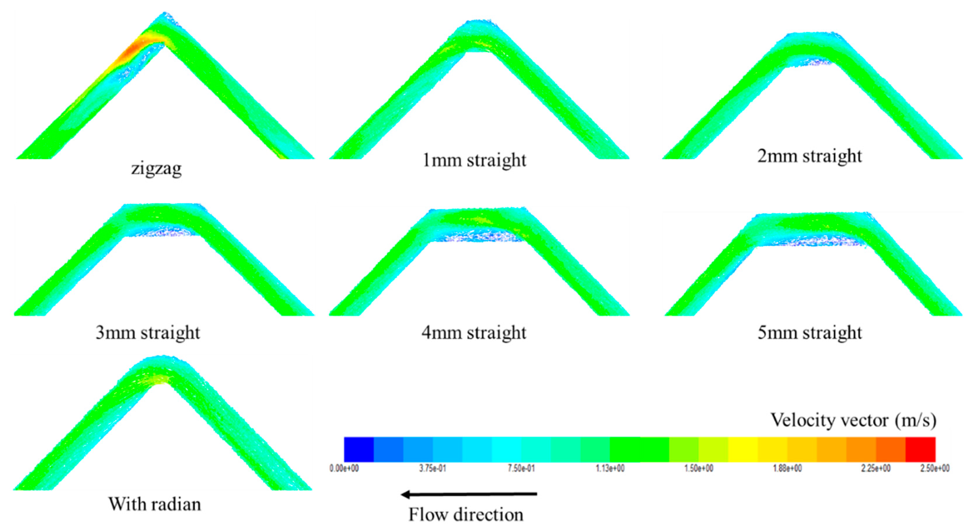
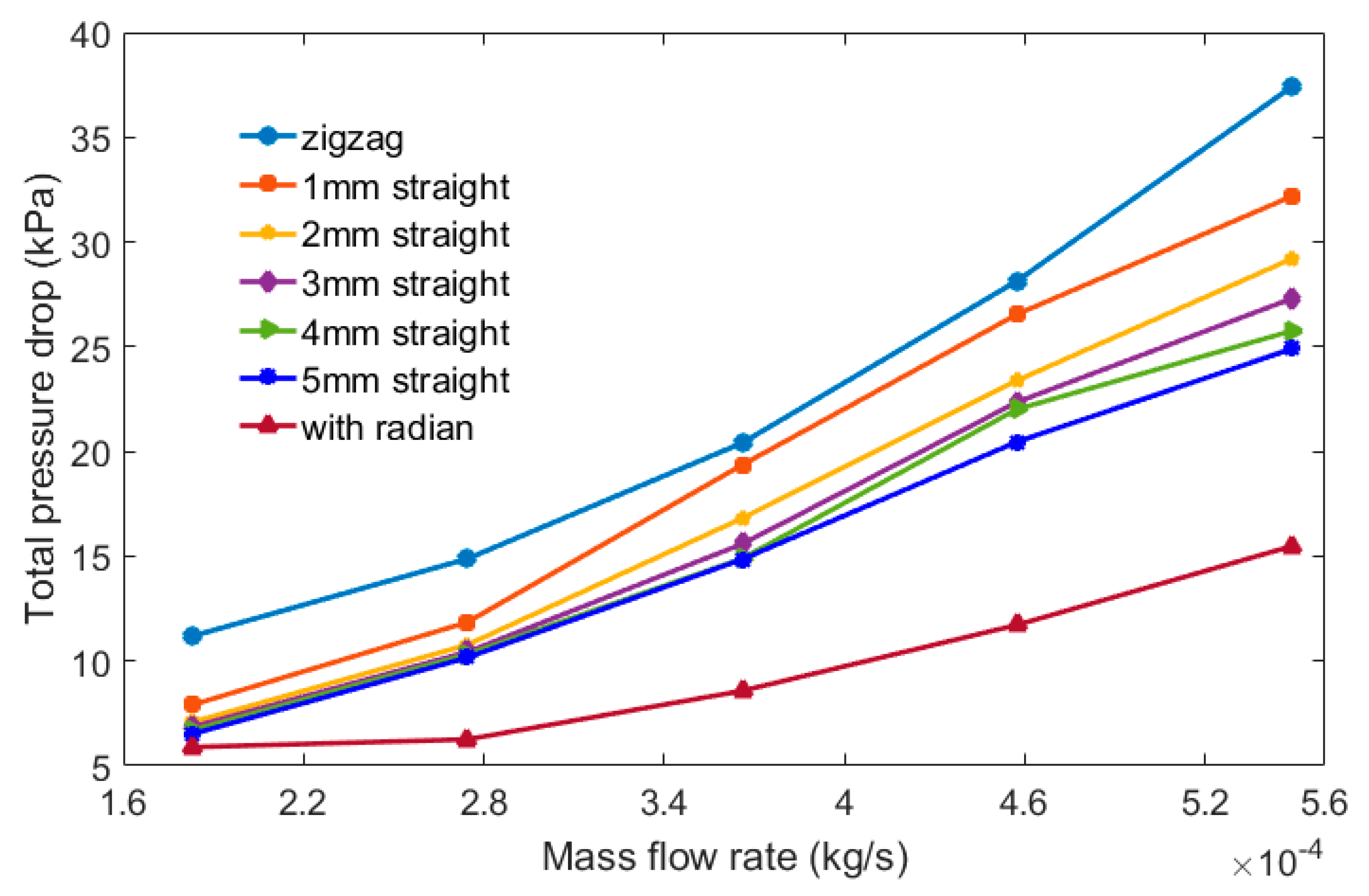
The following factors affecting the pressure drop can be summarized: (a) increasing velocity leads to an increase in pressure drop, (b) the flow separation and dead zones occurring in the channel increase the pressure drop, (c) the longer the path of the LNG flowing through the channel, the greater the pressure drop, and (d) the stronger the channel disturbance on the fluid, the greater the pressure drop;
(2)
The pressure drop is largest in the zigzag channel, while it is smallest in the zigzag channel with radian. For the zigzags with the inserted straight channels, as the inserted straight channel length increases, the pressure drop decreases;
(3)
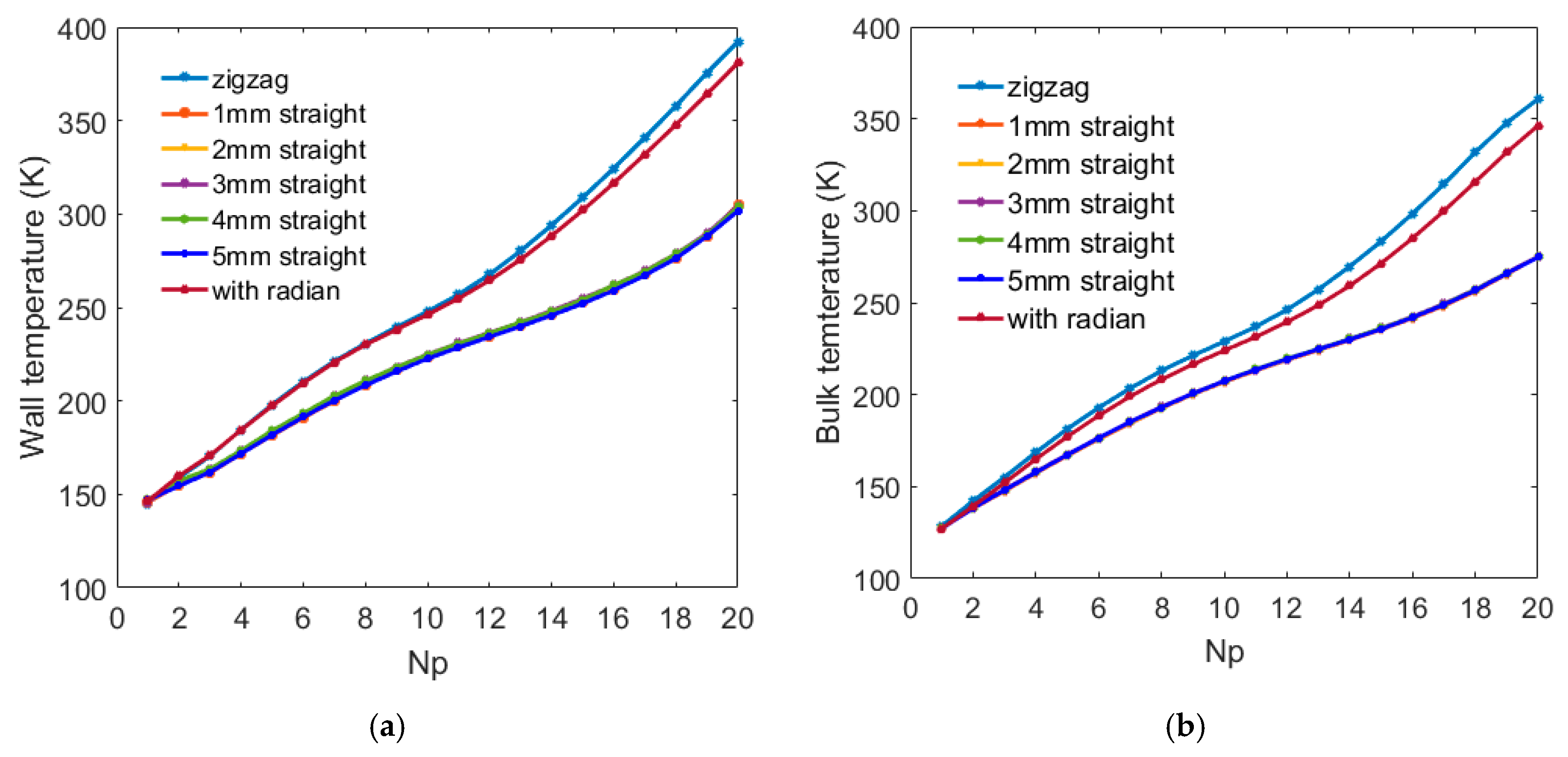
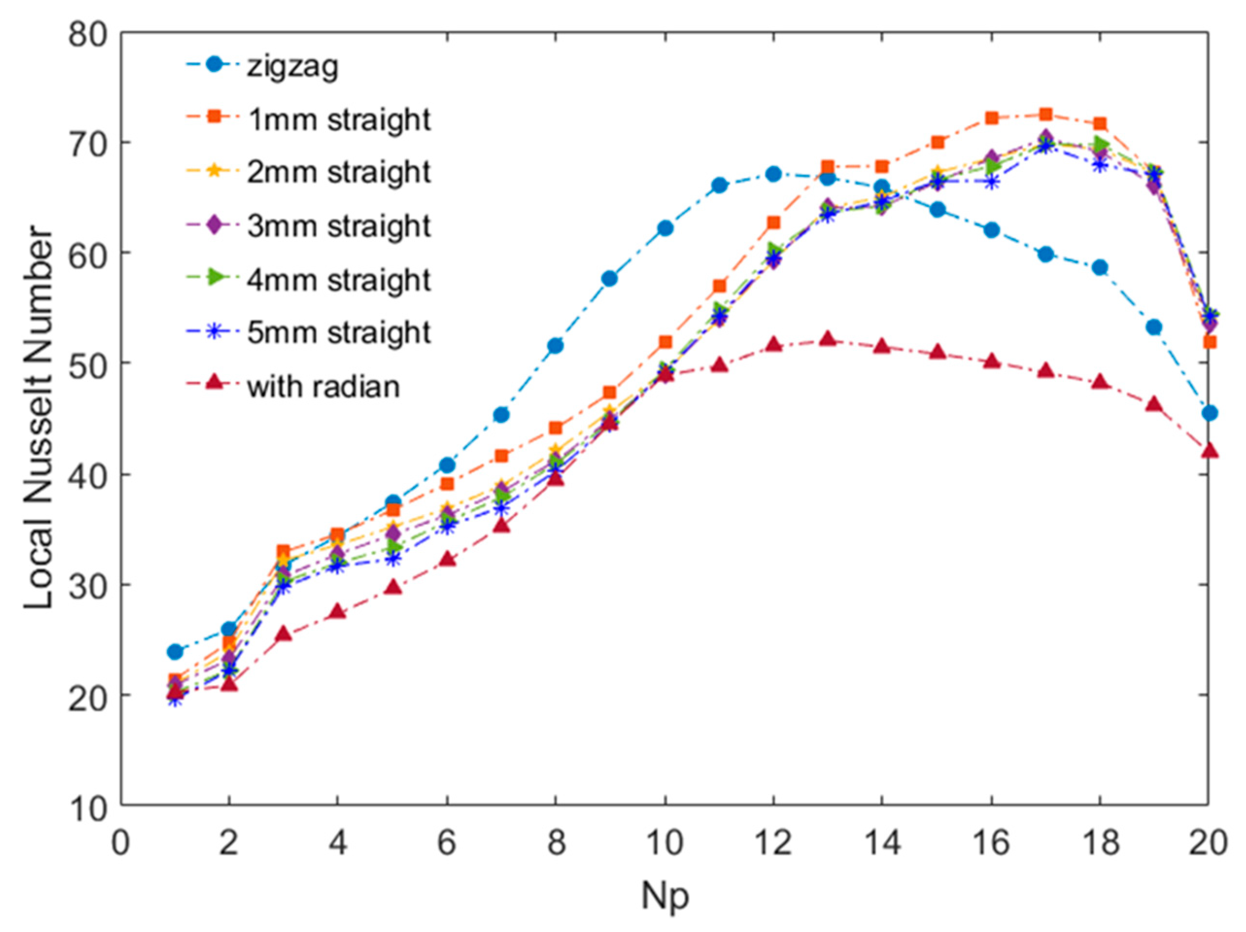
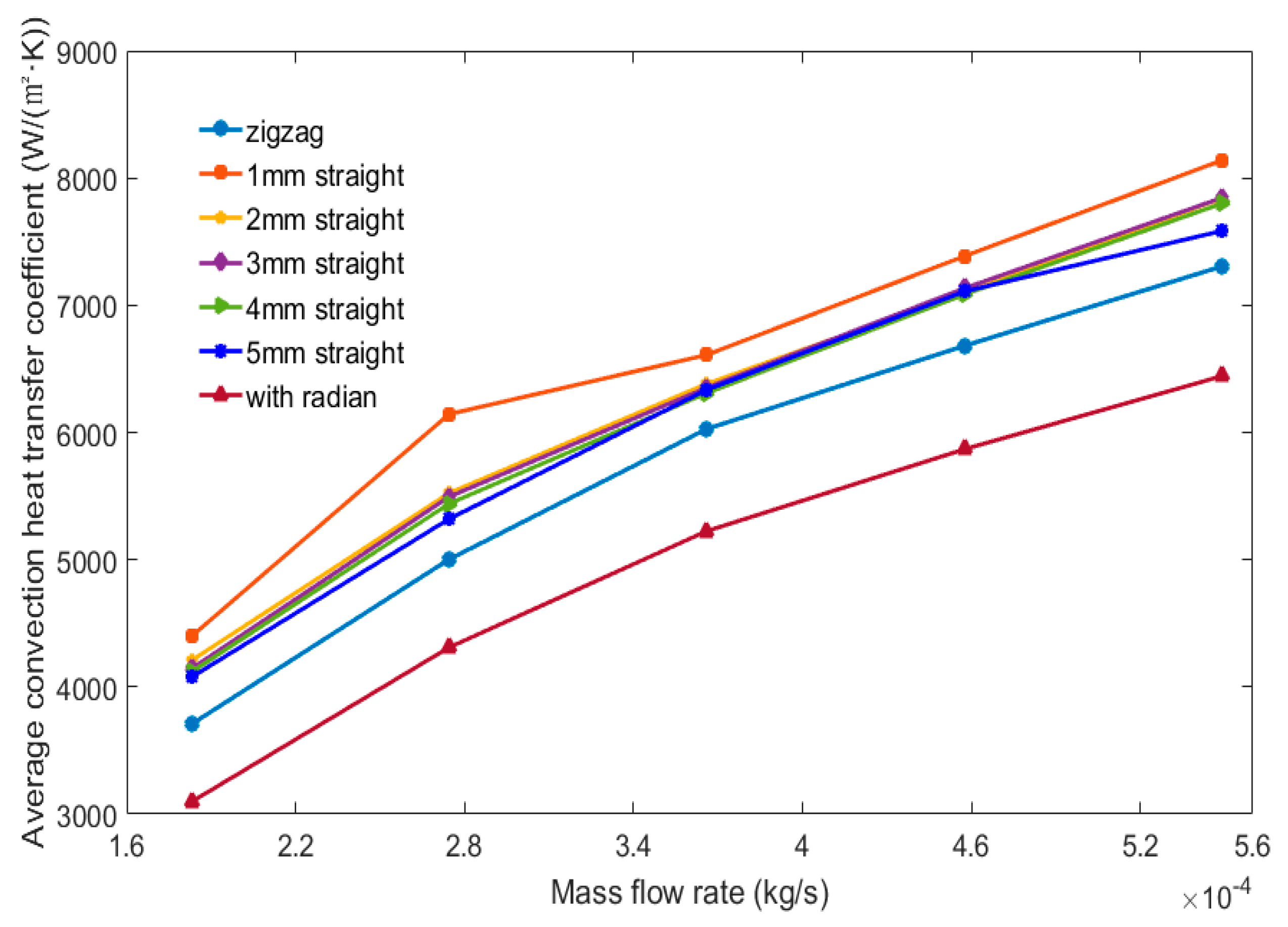
The convection heat transfer coefficient is largest in the zigzag with the inserted straight channel, and it is higher in the zigzag with 1 mm inserted straight channel. The zigzag channel with radian has a relative low convection heat transfer coefficient;
(4)
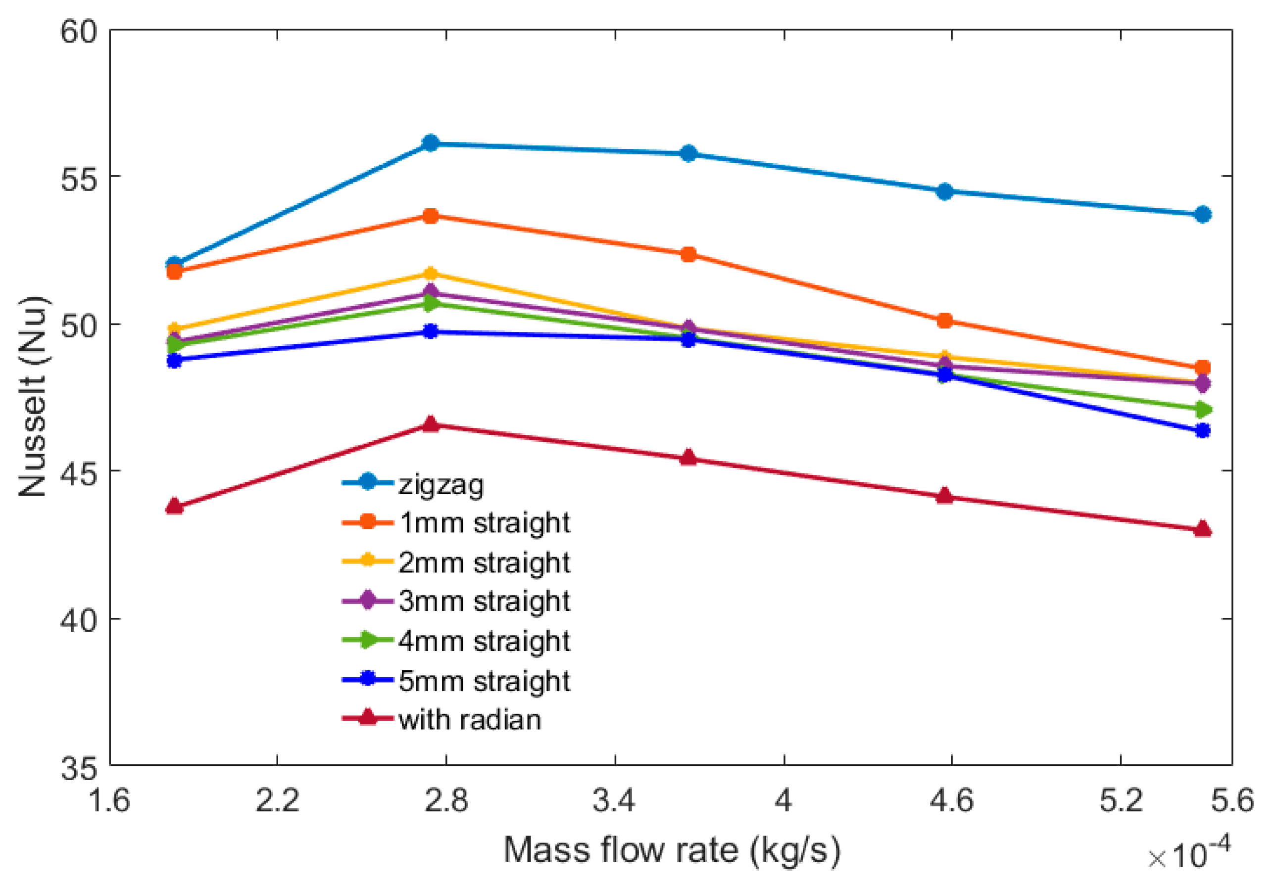
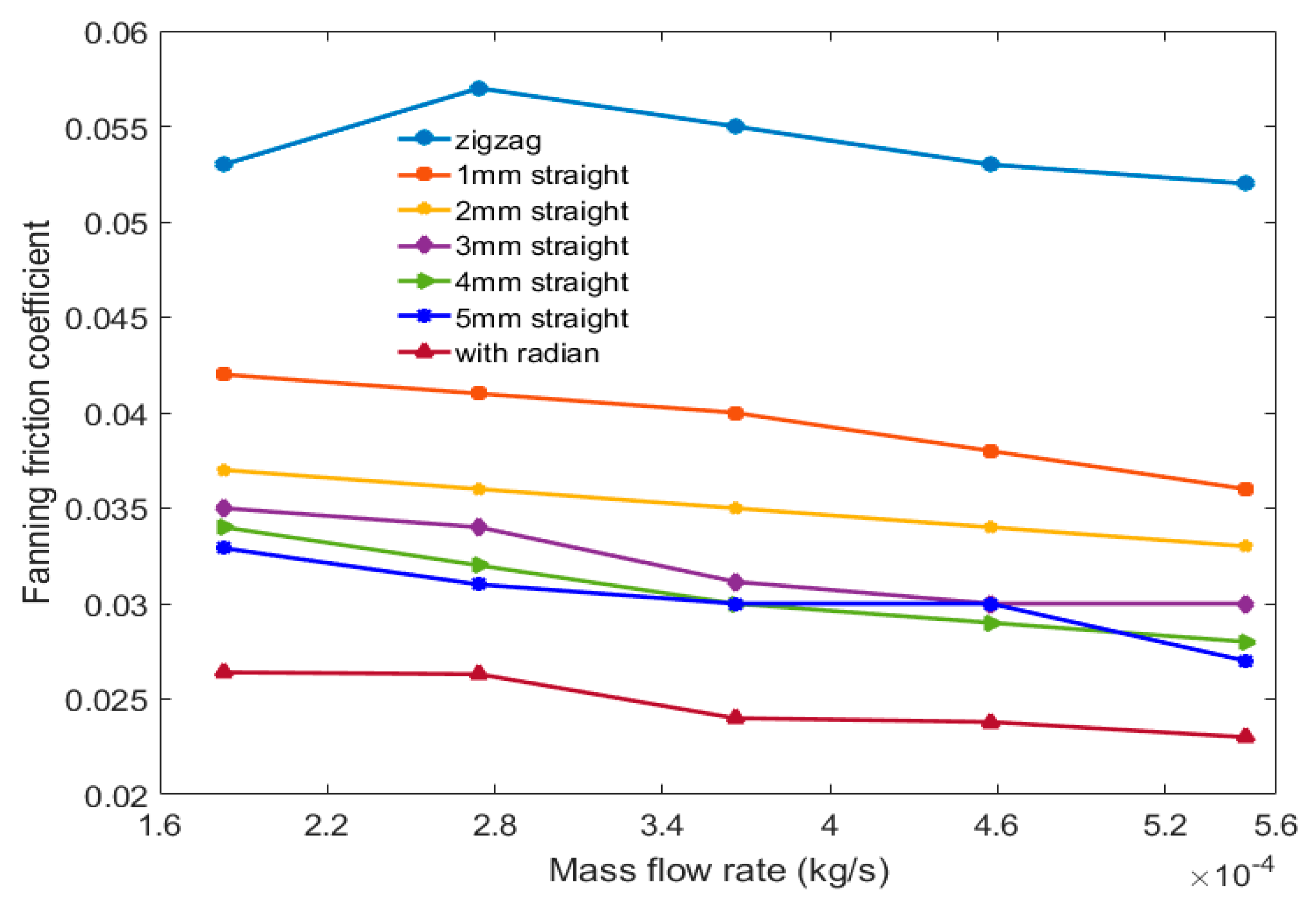
With the mass flow rate within the range 1.83 × 10⁻⁴–5.49 × 10⁻⁴ kg/s, the zigzag channel has a relatively high Nu and pressure drop characteristics; the convection heat transfer coefficient and Fanning friction coefficient for the zigzag channel with radian are the smallest. The pressure drop and the heat transfer performance decrease with the increase of the inserted straight channel length. The Nu and Fanning friction coefficient of the different channel shapes decrease with the increasing mass flow rate.
(5)
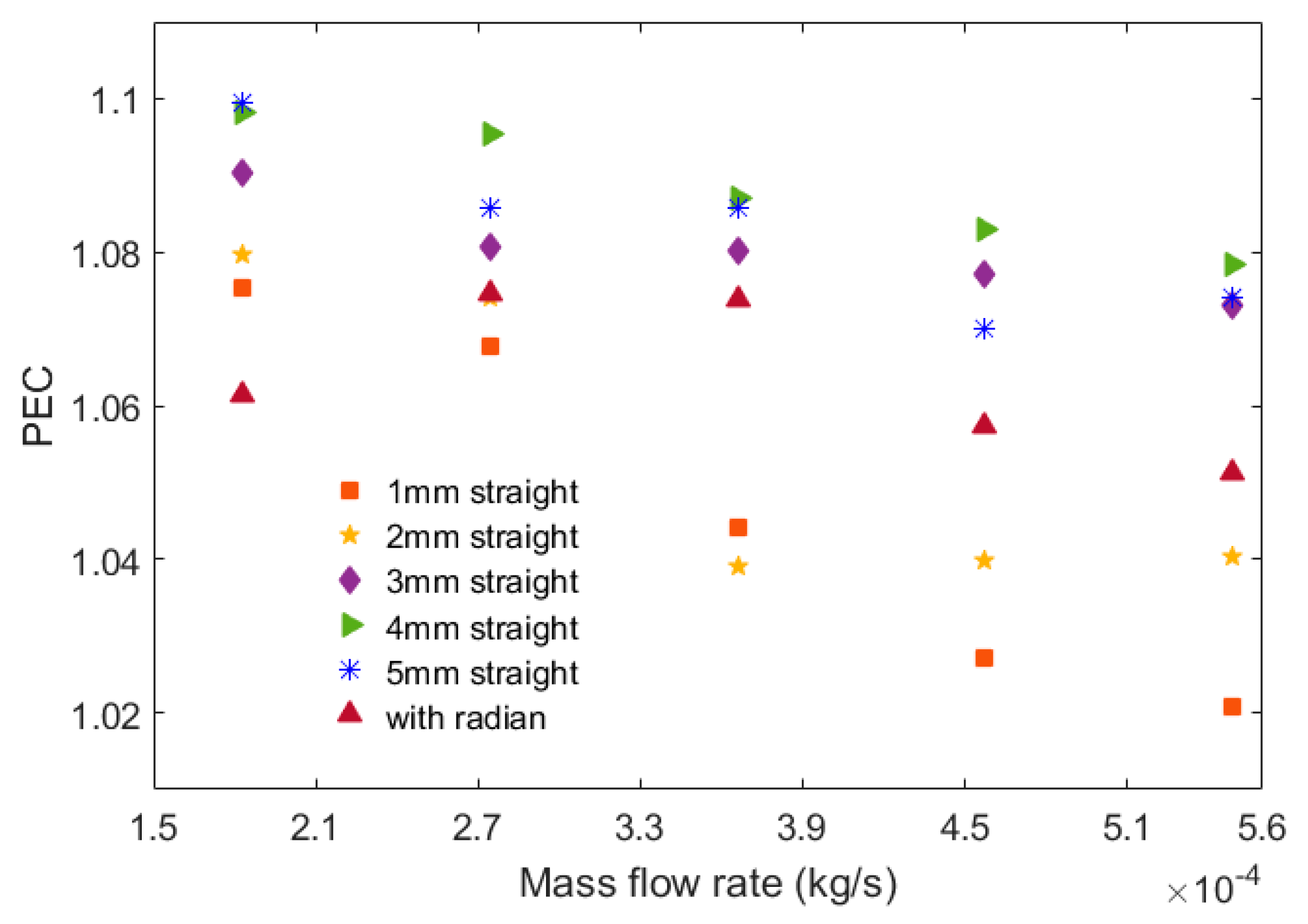
The PEC of the zigzags with the inserted straight channels and the zigzag channel with radian are greater than 1, and the values are higher at lower mass flow rates, indicating that the best heat transfer performances are those in the zigzags with the inserted straight channels and the zigzag channel with radian. Additionally, the PEC are higher at lower mass flow rates. Moreover, the zigzag with the 4 mm inserted straight channel has a higher heat transfer performance.

Author Contributions

Conceptualization and supervision, Z.Z.; formal analysis and data curation, Y.Z.; validation, methodology, and software, X.M., X.C., S.L., S.Y., and Z.Z.; writing—original draft preparation, Y.Z. and Z.Z.

Funding

The authors gratefully acknowledge that this work was supported by the Jiangsu marine and fishery science and technology innovation and extension project (HY2017-8) and the Zhenjiang funds for the key research and development project (GY2016002-1).

Conflicts of Interest

The authors declare no conflict of interest.

Nomenclature

TTemperature (K)
PPressure (Pa)
Llength of channel (mm)
fFanning friction factor
vVelocity (m/s)
hConvective heat transfer coefficient (W/(m2·K))
NuNusselt number
CpSpecific heat (kJ/(kg·K))
Dhhydraulic diameter (m)
Gmass flow rate (kg/s)
ΔPpressure drop (Pa)
Δ P f pressure drop due to friction (Pa)
Δ P a pressure drop due to acceleration (Pa)
PECPerformance Evaluation Criteria
Greek symbols
µviscosity (Pa·s)
ρdensity (kg/m3)
λthermal conductivity (W/m·K)
Subscript
wWall
bBulk mean
ininlet
outoutlet

References

  1. Zhang, P.; Ma, T.; Ke, H.; Wang, W.; Lin, Y.; Wang, Q. Numerical investigation on local thermal characteristics of printed heat exchanger for natural gas liquefication. Energy Procedia 2019, 158, 5408–5413. [Google Scholar] [CrossRef]
  2. Mortean, M.V.V.; Paiva, K.V.; Mantelli, M.B.H. Diffusion bonded cross-flow compact heat exchangers: Theoretical predictions and experiments. Int. J. Therm. Sci. 2016, 110, 285–298. [Google Scholar] [CrossRef]
  3. Yoon, S.H.; No, H.C.; Kang, G.B. Assessment of straight, zigzag, S-shape, and airfoil PCHEs for intermediate heat exchangers of HTGRs and SFRs. Nucl. Eng. Des. 2014, 270, 334–343. [Google Scholar] [CrossRef]
  4. Zhao, Z.; Zhang, X.; Zhao, K.; Jiang, P.; Chen, Y. Numerical investigation on heat transfer and flow characteristics of supercritical nitrogen in a straight channel of printed circuit heat exchanger. Appl. Therm. Eng. 2017, 126, 717–729. [Google Scholar] [CrossRef]
  5. Huang, C.; Cai, W.; Wang, Y.; Liu, Y.; Li, Q.; Li, B. Review on the characteristics of flow and heat transfer in printed circuit heat exchangers. Appl. Therm. Eng. 2019, 153, 190–205. [Google Scholar] [CrossRef]
  6. Chen, M.; Sun, X.; Christensen, R.N.; Shi, S.; Skavdahl, I.; Utgikar, V.; Sabharwall, P. Experimental and numerical study of a printed circuit heat exchanger. Ann. Nucl. Energy 2016, 97, 221–231. [Google Scholar] [CrossRef] [Green Version]
  7. Mylavarapu, S.K.; Sun, X.; Glosup, R.E.; Christensen, R.N.; Patterson, M.W. Thermal hydraulic performance testing of printed circuit heat exchangers in a high-temperature helium test facility. Appl. Therm. Eng. 2014, 65, 605–614. [Google Scholar] [CrossRef]
  8. Chen, M.; Sun, X.; Christensen, R.N.; Skavdahl, I.; Utgikar, V.; Sabharwall, P. Dynamic behavior of a high-temperature printed circuit heat exchanger: Numerical modeling and experimental investigation. Appl. Therm. Eng. 2018, 135, 246–256. [Google Scholar] [CrossRef]
  9. Zheng, Z.; Fletcher, D.F.; Haynes, B.S. Transient laminar heat transfer simulations in periodic zigzag channels. Int. J. Heat Mass Transf. 2014, 71, 758–768. [Google Scholar] [CrossRef]
  10. Lee, S.M.; Kim, K.Y. Optimization of zigzag flow channels of a printed circuit heat exchanger for nuclear power plant application. J. Nucl. Sci. Technol. 2012, 49, 343–351. [Google Scholar] [CrossRef] [Green Version]
  11. Kim, I.H.; No, H.C. Physical model development and optimal design of PCHE for intermediate heat exchangers in HTGRs. Nucl. Eng. Des. 2012, 243, 243–250. [Google Scholar] [CrossRef]
  12. Yang, Y.; Li, H.; Yao, M.; Gao, W.; Zhang, Y.; Zhang, L. Investigation on the effects of narrowed channel cross-sections on the heat transfer performance of a wavy-channeled PCHE. Int. J. Heat Mass Transf. 2019, 135, 33–43. [Google Scholar] [CrossRef]
  13. Tsuzuki, N.; Kato, Y.; Nikitin, K.; Ishizuka, T. Advanced Microchannel Heat Exchanger with S-shaped Fins. J. Nucl. Sci. Technol. 2009, 46, 403–412. [Google Scholar] [CrossRef]
  14. Chu, W.X.; Li, X.H.; Ma, T.; Chen, Y.T.; Wang, Q.W. Study on hydraulic and thermal performance of printed circuit heat transfer surface with distributed airfoil fins. Appl. Therm. Eng. 2017, 114, 1309–1318. [Google Scholar] [CrossRef]
  15. Zhang, H.; Guo, J.; Huai, X.; Cheng, K.; Cui, X. Studies on the thermal-hydraulic performance of zigzag channel with supercritical pressure CO2. J. Supercrit. Fluids 2019, 148, 104–115. [Google Scholar] [CrossRef]
  16. Zhao, Z.; Zhao, K.; Jia, D.; Jiang, P.; Shen, R. Numerical Investigation on the Flow and Heat Transfer Characteristics of Supercritical Liquefied Natural Gas in an Airfoil Fin Printed Circuit Heat Exchanger. Energies 2017, 10, 1828. [Google Scholar] [CrossRef]
  17. Huang, D.; Wu, Z.; Sunden, B.; Li, W. A brief review on convection heat transfer of fluids at supercritical pressures in tubes and the recent progress. Appl. Energy. 2016, 162, 494–505. [Google Scholar] [CrossRef]
  18. Kim, D.E.; Kim, M.H.; Cha, J.E.; Kim, S.O. Numerical investigation on thermal–hydraulic performance of new printed circuit heat exchanger model. Nucl. Eng. Des. 2008, 238, 3269–3276. [Google Scholar] [CrossRef]
  19. Sung, J.; Lee, J.Y. Effect of tangled channels on the heat transfer in a printed circuit heat exchanger. Int. J. Heat Mass Transf. 2017, 115, 647–656. [Google Scholar] [CrossRef]
  20. Baek, S.; Kim, J.H.; Jeong, S.; Jung, J. Development of highly effective cryogenic printed circuit heat exchanger (PCHE) with low axial conduction. Cryogenics 2012, 52, 366–374. [Google Scholar] [CrossRef]
  21. Lee, S.M.; Kim, K.Y.; Kim, S.W. Multi-objective optimization of a double-faced type printed circuit heat exchanger. Appl. Therm. Eng. 2013, 60, 44–50. [Google Scholar] [CrossRef]
  22. Jeon, S.; Baik, Y.J.; Byon, C.; Kim, W. Thermal performance of heterogeneous PCHE for supercritical CO2 energy cycle. Int. J. Heat Mass Transf. 2016, 102, 867–876. [Google Scholar] [CrossRef]
  23. Zhao, Z.; Zhou, Y.; Ma, X.; Chen, X.; Li, S.; Yang, S. Numerical Study on Thermal Hydraulic Performance of Supercritical LNG in Zigzag-Type Channel PCHEs. Energies 2019, 12, 548. [Google Scholar] [CrossRef]
  24. Rogala, Z.; Brenk, A.; Malecha, Z. Theoretical and Numerical Analysis of Freezing Risk during LNG Evaporation Process. Energies 2019, 12, 1426. [Google Scholar] [CrossRef]
  25. Higashi, Y. NIST Thermodynamic and Transport Properties of Refrigerants and Refrigerant Matures (REFPROP). Netsu Bussei 2000, 4, 1575. [Google Scholar]
  26. Safaei, M.R.; Togun, H.; Vafai, K.; Kazi, S.N.; Badarudin, A. Investigation of Heat Transfer Enhancement in a Forward-Facing Contracting Channel Using FMWCNT Nanofluids. Numer. Heat Transf. Appl. 2014, 66, 1321–1340. [Google Scholar] [CrossRef]
Figure 1. The simplified numerical model: (a) the core of PCHE; (b) the shape of a single channel and boundary conditions.
Energies 12 02085 g001
Figure 2. Geometric sizes of the zigzag channel, the zigzags with the inserted straight channels, and the zigzag channel with radian.
Energies 12 02085 g002
Figure 3. Thermo-physical properties of supercritical LNG at 10 MPa.
Energies 12 02085 g003
Figure 4. Grid independence test.
Energies 12 02085 g004
Figure 5. Local pressure drop along the flow direction for different channel shapes.
Energies 12 02085 g005
Figure 6. Velocity vectors for different channel shapes.
Energies 12 02085 g006
Figure 7. Local convection heat transfer coefficient along the flow direction for different channel shapes.
Energies 12 02085 g007
Figure 8. (a) Wall temperature and (b) LNG bulk temperature for different channel shapes.
Energies 12 02085 g008
Figure 9. Nusselt number (Nu) along the flow direction for different channel shapes.
Energies 12 02085 g009
Figure 10. Average convection heat transfer coefficient of different channel shapes at different mass flow rates.
Energies 12 02085 g010
Figure 11. Nu of different channel shapes at different mass flow rates.
Energies 12 02085 g011
Figure 12. Total pressure drops for different channel shapes at different mass flow rates.
Energies 12 02085 g012
Figure 13. Velocity vectors of Np = 10 at different mass flow rates.
Energies 12 02085 g013
Figure 14. Fanning friction factor for different channel shapes at different mass flow rates.
Energies 12 02085 g014
Figure 15. Performance comparison for different channels at different mass flow rates.
Energies 12 02085 g015
Table 1. Details of boundary conditions.
InletOutletTop/Bottom Walls
Pressure (MPa)Temperature (K)Mass flow rate (kg/s)Pressure outletConstant heat flux (W/m2)
101211.83 × 10−47.5 × 10⁴
Table 2. Comparison between simulation and experimental results at 10 MPa: relative error.
TitleSimulation ResultsExperiment DataRelative Error (%)
Temperature difference ΔT (K)186.4186.60.11
Pressure difference ΔP (Pa)10,189.4510,578.63.82

