Article

Effect of Actual Gas Turbine Operating Conditions on Mist/Steam Cooling Performance in a Ribbed Passage

1
MOE Key Laboratory of Thermo-Fluid Science and Engineering, School of Energy and Power Engineering, Xi’an Jiaotong University, Xi’an 710049, China
2
Department of Thermal Power Engineering, School of Energy and Power Engineering, Xi’an Jiaotong University, Xi’an 710049, China
*
Author to whom correspondence should be addressed.
Energies 2019, 12(10), 2015; https://doi.org/10.3390/en12102015
Submission received: 17 March 2019 / Revised: 8 May 2019 / Accepted: 22 May 2019 / Published: 26 May 2019

Abstract

:
This study numerically examines the effect of actual gas turbine operating conditions on heat transfer characteristics in a ribbed passage with mist/steam cooling. A 60° ribbed passage with aspect ratio of 1/1 was investigated at Reynolds number of 300,000, and steam cooling was used to provide a contrast. Three main factors were considered: coolant temperature, operating pressure, and wall heat flux density. The heat transfer enhancement mechanism of mist/steam cooling was explored, and the results showed that the heat transfer performance of mist/steam cooling was superior to steam cooling. When the coolant temperature varied from 300 to 500 °C, the average Nusselt number of mist/steam cooling decreased by 26.6%, and the heat transfer enhancement ratio dropped from 15% to 10%. As operating pressure increased, the heat transfer performance factor of mist/steam firstly increased and then decreased. At an operating pressure of 1.5 MPa, the heat transfer achieved its optimal performance, and the heat transfer enhancement ratio achieved its maximum value of 15.9%. Larger wall heat flux density provided less heat transfer enhancement. When the heat flux density increased from 100,000 to 300,000 W·m−2, the average Nusselt number of mist/steam cooling decreased by 13.8%, while the heat transfer enhancement ratio decreased from 25.3% to 12.6%.

1. Introduction

Gas turbines have extensive applications in many important energy production fields, such as aeronautical power, ship propulsion, and power generation. Research has shown that increasing the inlet temperature of the gas turbine is the main approach to enhance its cycle efficiency and output power [1]. With the continuous development of gas turbine technology, the inlet temperature of gas turbines is continuously increasing, exceeding far beyond the allowable temperature for the metal substance of turbine blades. The larger thermal stress caused by the erosion of high-temperature gas not only reduces the mechanical properties of the metal blades but can also easily cause the blade to burn and to be destroyed, which will seriously affect the economy and safety of the gas turbine operation. Therefore, many scholars are devoted to the research on efficient cooling of gas turbine blades.
Back in the 1980s, air was adopted as the coolant for the cooling of gas turbine blades. In the last decades, many researchers have focused on the influence of air cooling technology on the heat transfer performance of gas turbine blades under different structural parameters or various flow conditions [2,3,4,5]. However, with the continuous increase in inlet temperature of advanced gas turbines, an increasingly greater amount of cooling air is needed, which will weaken the efficiency of gas turbines to a large extent. To solve this problem, steam cooling technology is applied for the cooling of gas turbine blades because steam has better thermophysical properties. Many studies have been carried out on the steam cooling technology for gas turbine blades in order to obtain higher heat transfer performance [6,7,8,9,10]. Although steam cooling of gas turbine blades can decrease air consumption and reduce aerodynamic and thermodynamic loss, a large amount of steam consumption will also lead to many obvious problems, such as low thermal efficiency and more pressure loss, especially in complex ribbed channels. Consequently, one of the challenges for applying traditional air cooling or steam cooling is the low cooling efficiency and large coolant consumption. To meet the requirement of current gas turbines with higher performance, a new cooling technology called the mist/steam two-phase cooling technology has appeared in recent years.
Compared with traditional air cooling and steam cooling, the mist/steam two-phase cooling technology can not only reduce the consumption of coolants but also improve the heat transfer performance of gas turbines. Consequently, it has already attracted a lot of research attention [11,12,13,14].
At the beginning of the 21st century, Guo et al. [14,15,16] experimentally studied the heat transfer performance of mist/steam flow in horizontal straight pipes and 180° bend pipes. They found that the addition of a small amount of droplet could significantly improve the heat transfer enhancement performance. For the horizontal straight pipe, an addition of 5% droplet increased the heat transfer coefficient by 50–100%. For the 180° elbow pipe, an addition of 1–2% droplet increased the heat transfer coefficient by 40–300%. The wall heat transfer coefficient increased with the increase in the steam mass flow rate and decreased with the increase in the wall heat flux density. Subsequently, Dhanasekaran et al. [17,18] conducted a Euler–Lagrange numerical simulation study to verify the heat transfer performance of mist/steam cooling in a horizontal straight pipe and a 180° pipe. The results showed that the maximum numerical prediction error of the steam cooling pipeline was 8%, while that of the mist/steam cooling pipeline was 16%. Elwekeel et al. [19,20] used numerical methods to study the heat transfer performance of square ribs, triangular ribs, and trapezoidal ribs in a 90° transverse ribbed channel. The heat transfer performance of the four coolants—mist/steam, mist/air, steam, and air—were compared, and the results showed that the best heat transfer performance was obtained using mist/steam. In addition, the heat transfer performance of steam could be improved by 130% with the addition of 6% droplets. Liao et al. and Zhang et al. [12,21] adopted a numerical method to compare the heat transfer performance of mist/steam, mist/air, steam, and air in a ribbed wedge-shaped channel and a 45° U-shaped channel. Their results also showed that mist/steam cooling had the best heat transfer performance among the four coolants. Shi et al. [22,23] investigated the effects of Reynolds number, droplet concentration, wall heat flux density, and droplet transport characteristics on the heat transfer performance of mist/steam in a smooth, square passage of turbine blades. Their experiments showed that the heat transfer coefficient of mist/steam was 3.46 times that of pure steam. The heat transfer coefficient of mist/steam increased with the increase of Reynolds number and droplet concentration, while it decreased with the increase in wall heat flux density. Jiang et al. [13] studied the heat transfer characteristics of mist/steam cooling in a 60° ribbed straight channel using both experimental and numerical methods.
The above studies show that mist/steam two-phase flow cooling has good heat transfer enhancement characteristics under the experimental conditions of low temperature, low pressure, low density, and low Reynolds number. However, actual gas turbines work in high temperature, high pressure, and high heat flux density. Such operating conditions not only significantly change the physical properties of steam but also greatly affect the evaporation rate and the dynamic characteristics of droplets. Therefore, the operating conditions of actual gas turbines have a strong influence on the cooling performance of mist/steam two-phase flow. So far, few researchers have studied the cooling characteristics of mist/steam two-phase flow in ribbed channels under the actual operating conditions of gas turbines.
In this work, a numerical study of the effect of high temperature, high pressure, and high heat flux density on the heat transfer characteristics of mist/steam two-phase flow cooling in gas turbine ribbed channels was carried out in detail using actual operating conditions. The corresponding influence mechanisms of each actual operating condition on the heat transfer enhancement performance of mist/steam cooling were also explored. Furthermore, some quantitative comparisons regarding heat transfer enhancement were conducted between mist/steam cooling and steam cooling. Based on the results, some new conclusions were obtained.

2. Numerical Method

2.1. Geometric Model and Grid Dependency

The dimension of the geometric model adopted in this paper was identical to the experimental research in [24]. A schematic diagram of the computational geometry is shown in Figure 1a, and the numerical calculation model is shown in Figure 1b. The numerical calculation model was mainly composed of an extended inlet section Le, a ribbed channel section Lh, and an extended outlet section Lo. In order to obtain fully developed flow conditions, the inlet section was extended. Meanwhile, the outlet section was extended to effectively avoid backflow. The detailed parameters were set as follows: channel aspect ratio W/H = 1/1; section size, 40 × 40; rib angle α = 60°; rib height e = 1.9 mm; channel hydraulic diameter D = 40 mm; rib spacing p/e = 10; length of the heating section of the ribbed channel Lh = 400 mm; extended inlet section Le = 200 mm; extended outlet section Lo = 100 mm. Symmetric wall boundary conditions were adopted to reduce the computational cost as the geometric model had symmetry in the y-axis direction.
As for the grid meshing, the ANSYS ICEM CFD software was used, and the structured meshing method was adopted. The mesh near the ribbed surface and the smooth surface on both sides were refined, and y+ < 1 was guaranteed to meet the requirements of the automatic wall function of the ANSYS CFX solver. The detailed grid meshing of the ribbed channel in the fully developed flow section is shown in Figure 2a. The grid dependency of the geometric model was carried out before the numerical calculation, as shown in Figure 2b. When the number of meshes exceeded 3.23 million, the Nusselt number on the center line of the ribbed surface no longer changed with the increase in the number of grids. In order to ensure accuracy of the calculation, 4.26 million grids were finally selected for numerical calculation.
The ANSYS CFX software (14.5, ANSYS, Xi’an, PRC) (Version, Manufacturer, City, State abbrev if USA or Canada, Country) was used to carry out steady, complicated three-dimensional numerical simulations. The two coolants—mist/steam and steam—were assumed to have constant thermophysical properties. Considering the actual operational condition of gas turbines, compressible and highly turbulent flow were supposed. After review, the shear stress transport (SST) k-ω model, which manages to well predict flow fields, was adopted to obtain the turbulent characteristics. The Euler-Lagrangian particle-tracking method was adopted to numerically simulate mist/steam two-phase flow. The discrete phase adopted the Lagrangian method to capture the motion trajectory of the droplet, and the continuous phase used the Euler method for numerical calculation. The fully coupled bidirectional coupling method was used to consider the interaction between the droplet and the gas flow. Latent heat in phase transition was introduced into the analysis of temperature field during the droplet evaporation process, and the saturation temperature was hypothesized relative to pressure. The governing equations in the domain were solved by the finite volume method. The convection term and diffusion terms were discretized by secondary-order accuracy scheme. The simulations were thought converged when the root mean square (RMS) residuals of the continuous equation, momentum equation, energy equation, and turbulence equation were less than 10−5. Simultaneously, the average temperature of the ribbed wall, the outlet temperature, and the mass flow rate of the outlet were monitored to ensure that the steady numerical calculation was converged.

2.2. Data Deduction

The inlet Reynolds number (Re) of the ribbed channel is defined as follows:
R e = ρ u D μ
where ρ is the coolant density at the inlet; u is the inlet velocity; D is the hydraulic diameter; and μ is the dynamic viscosity of the coolant.
The friction factor (f) is computed as follows:
f = Δ P 2 ρ u 2 D L h
where ΔP and Lh are pressure and length of heated section, respectively.
Nusselt number (Nu) is given by the following equation:
N u = q T w T b D λ
where q is the heat flux density at the surface; Tw and Tb are wall temperature and fluid bulk temperature, respectively; and λ is the thermal conductivity of the coolant.
Heat transfer performance factor (η) is given by the following equation:
η = ( N u / N u 0 ) / ( f / f 0 ) 1 / 3
where Nu and f are Nusselt number and friction factor, respectively; Nu0 and f0 denote the corresponding values for the plain tube.

2.3. Numerical Method Validation

For the computational domain in Figure 1, the geometric parameters were derived from Shui et al. [24], who experimentally and numerically studied heat transfer characteristics in steam-cooled ducts with 60° rib turbulators. Hence, it was necessary to validate the turbulence model compared with the experimental results. Accordingly, the boundary conditions for validation of the numerical method were set as follows. Steam was selected as the working fluid; the operating pressure and temperature were 0.3 MPa and 447 K, respectively; and heat flux on the heated wall was fixed at 5000 W·m−2.
Four turbulence models were compared: standard k-ε model, renormalization group (RNG) k-ε model, standard k-ω model, and SST k-ω model. The boundary conditions were identical to the literature [24]. Figure 3 shows the relationship between the average Nusselt number ( N u ¯ ) of the ribbed surface and the Reynolds number (Re) in the ribbed straight channels. It can be seen that the standard k-ε model and the RNG k-ε model significantly overestimated N u ¯ of all ribbed channels. Within the range of the tested Reynolds number, the predicted values of the standard k-ω model and the SST k-ω model were in good agreement with the experimental values. In contrast, the SST k-ω model had a slightly better prediction than the standard k-ω model, and the maximum error predicted by the SST k-ω model was about 5.76%. Because the standard k-ε model and the RNG k-ε model were not capable enough to accurately predict compressible flow and separation vortices, the corresponding calculation error was larger. On the other hand, the SST k-ω model avoided overestimating eddy viscosity with the consideration of turbulent stress. That made the loss function existing in the energy equation to be closer to the real value. As a result, the prediction error was lower, as shown in Figure 3. Therefore, the SST k-ω model was adopted in this study for subsequent numerical simulations.
As for the numerical validation of mist/steam two-phase flow, the experimental data conducted by Wang et al. [15] to study horizontal straight pipe mist/steam cooling characteristic was used for validation. The geometric model and boundary conditions were also identical to the experimental research [15], and the size of the geometric model is shown in Figure 4a. The heating section was set as the uniform heat flow, and the magnitude was 14,000 W·m−2. The inlet and outlet extended sections were set as insulated wall. The inlet Reynolds number of pipeline was Re = 20,000, the inlet steam temperature was 115 °C, and the static pressure in the outlet was 1 atm. As for the discrete phase, the droplet mass fraction was 5.7%, the droplet diameter was 6 μm, and the reflect discrete phase wall boundary condition was adopted. Meshing of the geometric model was conducted in ANSYS ICEM software, and structured grids were adopted. The near-wall grids were refined, as shown in Figure 4b, and y+ < 1 was guaranteed. After the grid dependency, the number of grids was finally determined to be 1.43 million.
Figure 5 shows the distribution of the heat transfer coefficient of the horizontal smooth tube mist/steam cooling wall. The trend of the heat transfer coefficient predicted by numerical simulation was consistent with the experimental data. Except for the area close to the exit area, i.e., in the area of x/d < 7, the predicted value of the wall heat transfer coefficient was in good agreement with the experimental data, and the maximum heat transfer coefficient error was about ±8.5%.

2.4. Boundary Conditions

The effect of actual operating conditions of gas turbines, such as inlet temperature (300–500 °C), operating pressure (0.5–5 MPa), and wall heat flux density (100,000–300,000 W·m−2), on the heat transfer characteristics of mist/steam two-phase flow were studied. The above operating conditions are the actual operating conditions of most ground gas turbines. In order to quantify the mist/steam cooling heat transfer enhancement ratio, steam cooling was selected as a comparative research condition. The mass flow rate in the channel inlet was set according to the Reynolds number, and the inlet temperature of the coolant was also fixed. The inlet turbulence intensity was set as 5%. The reference pressure was given in the calculation domain, and the outlet pressure was set as average static pressure of 0 MPa. The heat flux density was set at the channel ribbed surface and the smooth surfaces on both sides, the symmetry plane was set as symmetrical boundary condition, and the remaining wall surfaces were set as the adiabatic wall surface. All of the wall surfaces were nonslip wall. The droplet mass fraction of the discrete phase was fixed at 5%, the droplet diameter was 20 μm, and the discrete phase wall boundary condition was the reflect wall boundary condition. The specific boundary condition parameters are shown in Table 1.

3. Discussion of Numerical Results

If there were no extra explanations, the following simulated conditions were set. The steam Reynolds number was fixed as Re = 300,000, the coolant temperature was 300 °C, the operating pressure was 1.5 MPa, and the wall heat flux density was 200,000 W·m−2.

3.1. Effect of Coolant Temperature

In this study, the coolant temperature range was 300–500 °C. Figure 6 shows the variation in the average Nusselt number ( N u ¯ ) of the ribbed surface of mist/steam cooling and steam cooling channels with the coolant temperature. It can be seen that increasing the coolant temperature significantly reduced the heat transfer enhancement capacity of mist/steam cooling. When the steam temperature was increased from 300 to 500 °C, N u ¯ mist / steam decreased by 26.6%, while N u ¯ steam decreased by 23.5%. Compared with the steam cooling channel, the average Nusselt number heat transfer enhancement ratio ( N u ¯ mist / steam / N u ¯ steam ) decreased from 15% to 10%.
Figure 7 shows the effect of coolant temperature on the Nusselt number (Nu) distribution of the ribbed surface of the mist/steam cooling channel. It can be seen that the Nu distribution in all ribbed channels showed the same trend. As fluid flowed across the ribs, a cobblestone-shaped, high heat transfer region was generated between each rib, and the region grew larger as it came toward the exit. The Nu decreased gradually along the direction of the oblique ribs, while it increased gradually along the flow direction. However, with the increase in the coolant temperature, the Nu in the downstream region of the ribbed channel was significantly reduced.
Figure 8 shows the effect of the coolant temperature on the droplet motion trajectory in the mist/steam cooling channel. It can be seen that, with the increase in the coolant temperature, the running distance of the droplets in the ribbed channel gradually decreased. This was due to the increase in the coolant temperature increasing the evaporation rate of droplets, thereby shortening their lifespan. When the coolant temperature was 300 °C, the droplets could extend the entire ribbed channel heating section. During the evaporation process, droplets strongly mixed with the secondary flow generated in the channel (shown as the variation in the droplet motion trajectory in Figure 8). Consequently, the local heat transfer coefficient increased. When the coolant temperature exceeded 450 °C, droplets completely evaporated before entering the heating section. In contrast to what happened with 300 °C, there was no mixing mechanism between the droplets and the secondary flow. Furthermore, there was no local mainstream temperature decrease caused by the evaporation of droplets. This weakened the heat transfer performance of mist/steam cooling in the ribbed channel. This was also the reason N u ¯ mist / steam / N u ¯ steam gradually decreased with the increase in the coolant temperature, as shown in Figure 6. The above analysis shows that the droplets that can survive the ribbed channel can enhance the local heat transfer. This is the fundamental reason for the “distributed” cooling characteristic of mist/steam two-phase flow.
Figure 9 shows the variation in the heat transfer performance factor ( η ) of the mist/steam and steam cooling channels with the coolant temperature. It can be seen that the heat transfer performance of the two coolants decreased with the increase in the coolant temperature. η mist / steam was significantly better than η steam . When the steam temperature increased from 300 to 500 °C, η mist / steam decreased from 21.7% to 9.7% compared to η steam .

3.2. Effect of Operating Pressure

In this study, the operating pressure range was 0.5–5 MPa. Figure 10 shows the variation in the average Nusselt number ( N u ¯ ) of the ribbed surface of mist/steam and steam cooling channels with the operating pressure. It can be seen that N u ¯ mist / steam increased sharply and then gradually decreased with the increase in the operating pressure. Moreover, N u ¯ mist / steam peaked when the operating pressure was 1.5 MPa. In contrast, N u ¯ steam was relatively less affected by the operating pressure. With regard to the average Nusselt number heat transfer enhancement ratio ( N u ¯ mist / steam / N u ¯ steam ), it reached a maximum value of 15.9% when the operating pressure was 1.5 MPa. Then, with the increase in operating pressure, N u ¯ mist / steam / N u ¯ steam gradually decreased to 7.3%.
Figure 11 shows the variation in the Nusselt number (Nu) distribution of the ribbed surface of the mist/steam cooling channel with the operating pressure. It can be seen that Nu distributions under different P conditions were extraordinarily similar. High heat exchange areas gathered close to one side wall of the passage generated between ribs and became bigger along the passage. However, there were still subtle gradations of Nu on the contours. When the operating pressure was less than 1.5 MPa, Nu in the downstream area increased with the increase in the operating pressure. When the operating pressure exceeded 2.0 MPa, Nu of the ribbed channel surface decreased slightly with the increase in the operating pressure.
Figure 12 shows the variation in the droplet motion trajectory of the mist/steam cooling channel with the operating pressure. It can be seen that the operating pressure had a remarkable effect on the droplet motion trajectory. When the operating pressure was less than 1.5 MPa, the droplets could completely survive the entire ribbed channel heating section. In this process, the droplets moved with the mainstream to the downstream of the channel, where droplet evaporation phase transition occurred. Meanwhile, the droplets mixed with the complex secondary flow inside the channel. This significantly enhanced the heat transfer enhancement performance of mist/steam cooling. When the operating pressure was larger than 2.0 MPa, the evaporation rate of the droplets increased, and the running distance of the droplets decreased. The droplets completely evaporated before entering the heating section when the operating pressure exceeded 3.0 MPa. According to the analysis in Section 3.1, the heat transfer enhancement induced by the evaporation of droplets and the mixture with the secondary flow no longer existed, so the heat transfer enhancement performance of mist/steam cooling was weakened.
Figure 13 shows the variation in the heat transfer performance factor ( η ) of the mist/steam and steam cooling channels with the operating pressure. It can be seen that η mist / steam first increased and then decreased with the increase in the operating pressure, and it peaked when the operating pressure was 1.5 MPa. However, the variation in η steam was not obvious with the increase in the operating pressure. When the operating pressure was 1.5 MPa, η mist / steam was 21.7% higher than η steam .

3.3. Effect of Heat Flux Density

In this study, the wall heat flux density range was 100,000–300,000 W·m−2. Figure 14 plots the variation in the average Nusselt number ( N u ¯ ) of the ribbed surface of mist/steam and steam cooling channels with the wall heat flux density. It can be seen that both Numist/steam and Nusteam declined as the wall heat flux density increased. In the range of heat flux density investigated in this study, the decrease in N u ¯ mist / steam and N u ¯ steam reached 13.8% and 4.1%, respectively. The heat transfer enhancement ratio ( N u ¯ mist / steam / N u ¯ steam ) decreased from 25.3% to 12.6%.
Figure 15 shows the distribution of the mist/steam cooling passage with different wall heat flux densities. It can be seen that the Nu distribution characteristics of the high heat transfer regions were similar to the previous cases. The regions produced between ribs almost covered the whole downstream area of the ribbed surface, and the Nu presented a decreasing trend with the increase in wall heat flux on the surface.
Figure 16 presents the effect of the wall heat flux density on the droplet trajectories in the mist/steam cooling passage. From Figure 16a, it can be seen that the impact of q was quite limited. The trajectories were mainly affected by the secondary flow generated in the passage. Figure 16b plots the trajectories as viewed from the right side. It shows that the droplets spun around clockwise under the force of the main flow and the secondary flow. The droplet trajectories in the mainstream core region were hardly changed under various wall heat flux densities. However, the liquid drops near the ribbed surface traveled farther when the wall heat flux density declined. Due to the strong mixture between droplets and the main flow and secondary flow, heat and mass transfer were enhanced in the mainstream core region. When the droplets moved toward the heated wall, affected by the high heat flux, the evaporation rate increased rapidly. Due to this, the trajectories near the wall were shortened, while those in the mainstream were seldom impacted. For steam cooling, increasing heat flux lifted the fluid temperature near the wall, which reduced the temperature gradient of the thermal boundary layer. Hence, heat transfer was weakened. For mist/steam cooling, higher heat flux resulted in droplets failing to intrude into the region near the heated wall. The disturbance to the thermal boundary and the interaction between the droplets and the wall were both weakened. This explains why higher q provided lower heat transfer for mist/steam cooling.
Figure 17 shows the variations in η in the mist/steam and steam cooling passages with the wall heat flux density. For both coolants, η decreased as the wall heat flux density increased, with η in mist/steam cooling declining more quickly. For instance, when the wall heat flux density rose from 100,000 to 300,000 W·m−2, η in the mist/steam cooling passage decreased by 16.5%, while that of steam cooling decreased by 6.9%.

4. Conclusions

This study examined the heat transfer characteristics in a ribbed passage with mist/steam cooling under actual gas turbine operating conditions. The effects of the coolant temperature, the operating pressure, and the wall heat flux density were investigated. The influence mechanism of the operating conditions on the heat transfer enhancement performance of mist/steam cooling was also analyzed. The main conclusions are as follows:
(1)
Mist/steam cooling could enhance heat transfer in the ribbed passage under all working conditions used in this study, in contrast to steam cooling.
(2)
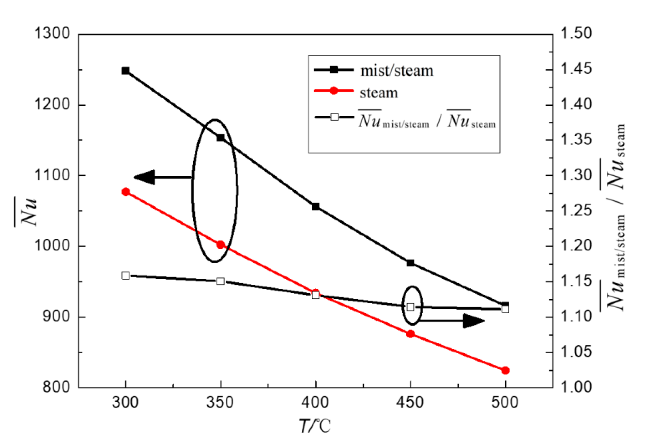
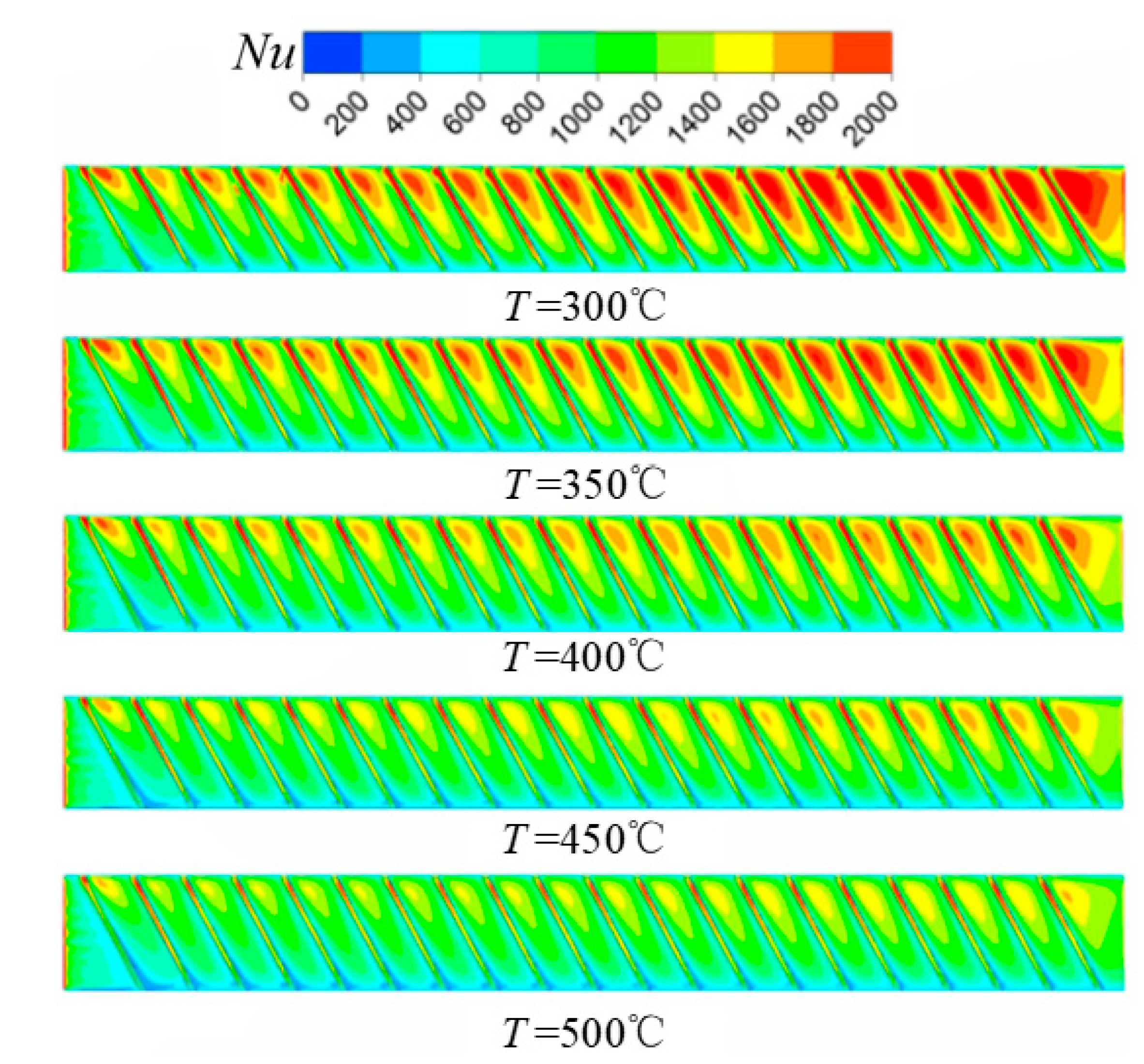
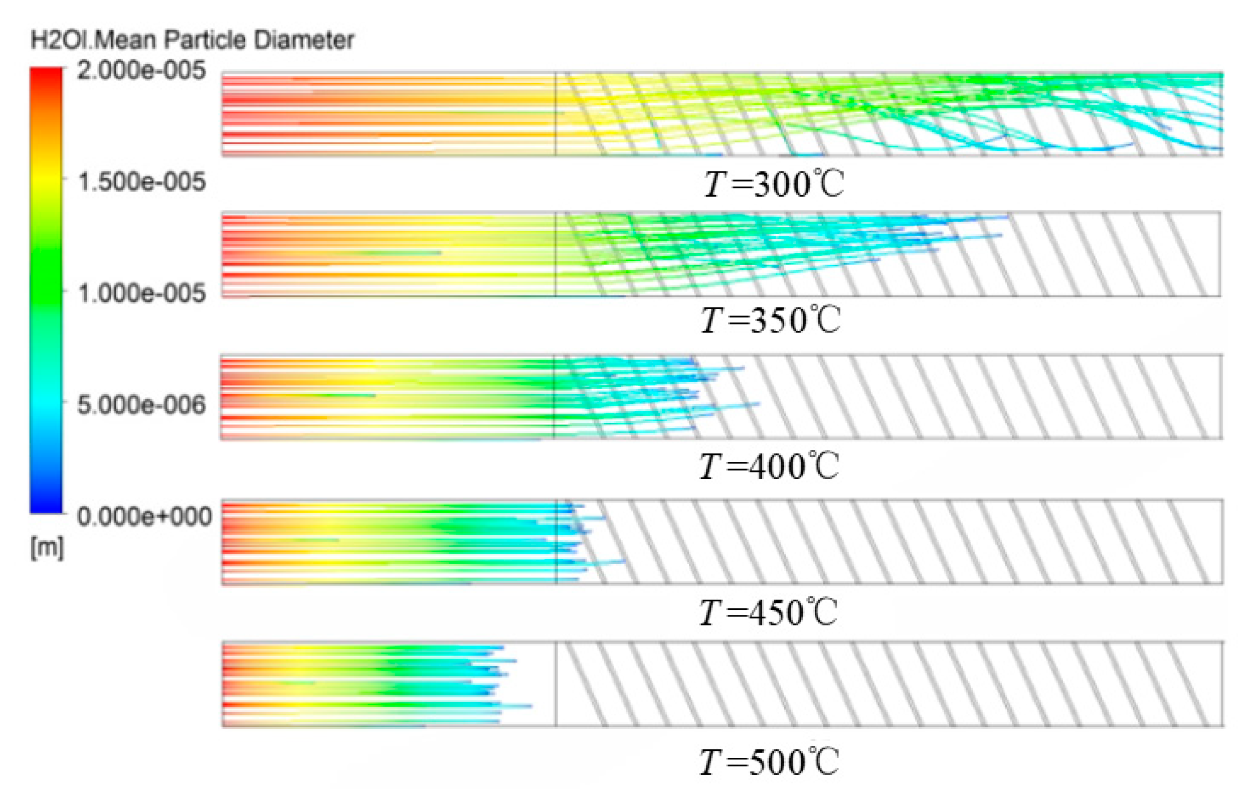
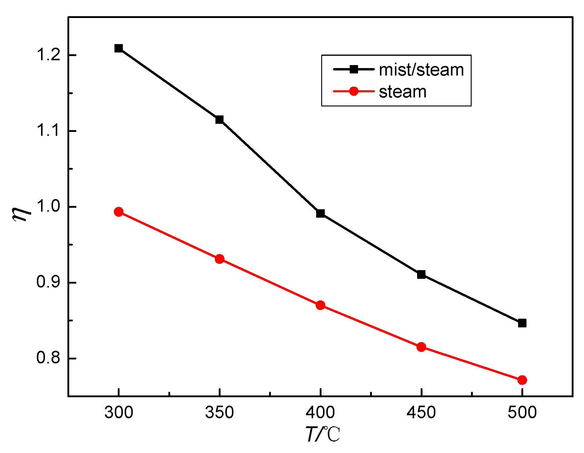
The average Nusselt number on the ribbed surface and the heat transfer performance factor decreased with the increase in the coolant temperature in both mist/steam cooling and steam cooling passages. However, the cooling performance of mist/steam was more sensitive to the coolant temperature. With the increase in the coolant temperature, the heat transfer enhancement ratio of mist/steam cooling in heat transfer decreased gradually. For mist/steam cooling, the average Nusselt number decreased by 26.6%, and the heat transfer enhancement ratio decreased from 15% to 10% when the coolant temperature varied from 300 to 500 °C.
(3)
The average Nusselt number and the heat transfer performance factor first increased and then decreased with the increase in the operating pressure, reaching the peak at the pressure of 1.5 MPa. Under that pressure, the heat transfer enhancement ratio of mist/steam cooling was enhanced by 15.9% compared with steam cooling.
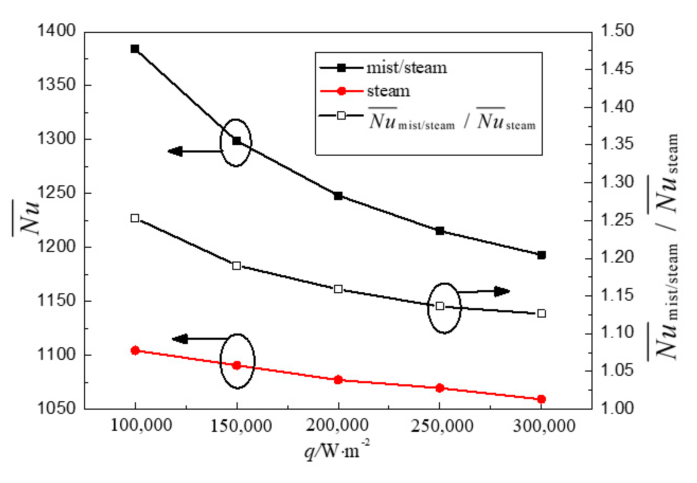
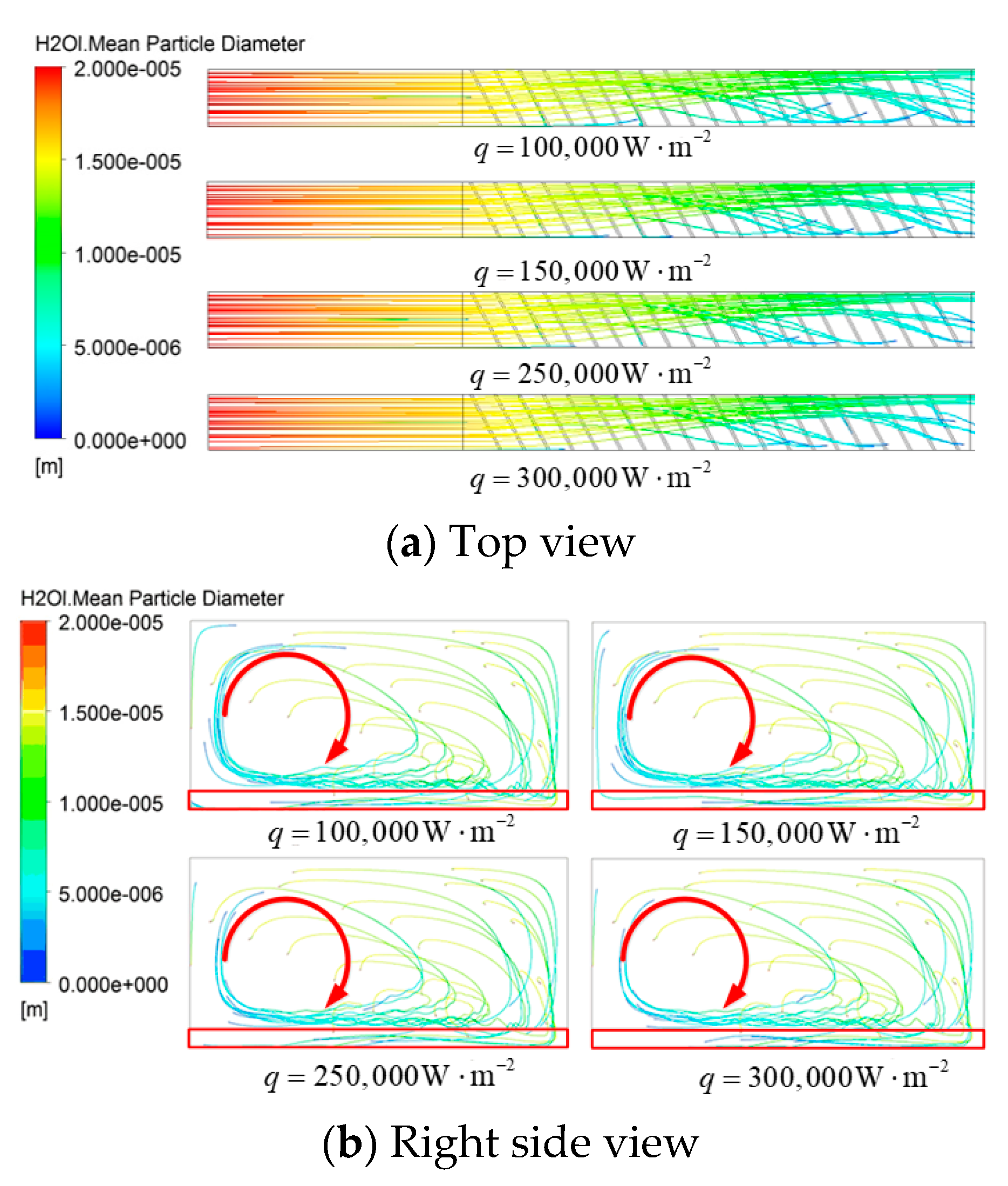
(4)
The heat transfer performance factor was greatly reduced with the increase in wall heat flux density. As the wall heat flux density rose from 100,000 to 300,000 W·m−2, the average Nusselt number of mist/steam cooling decreased by 13.8%. In the meantime, the heat transfer enhancement ratio of mist/steam cooling to steam cooling decreased from 25.3% to 12.6%.
(5)
Under actual operating conditions of gas turbines, it is recommended that higher steam Reynolds number (Re = 300,000), lower steam temperature (300 °C), medium operating pressure (1.5 MPa), and lower wall heat flux density (100,000 W·m−2) be used to obtain the optimal heat transfer enhancement performance of mist/steam cooling.

Author Contributions

Conceptualization, J.G. and T.G.; Data curation, J.G., T.G. and J.Z.; Investigation, J.G. and T.G.; Methodology, J.H. and J.Z.; Software, J.Z.; Supervision, J.G. and T.G.; Validation, J.G., J.Z., J.H., and Z.L.; Writing—original draft, J.G., J.H., and Z.L.; Writing—review & editing, J.G. and J.H.

Funding

The present paper is financially supported by the National Natural Science Foundation of China (No. 51776149, 51106013), which is gratefully acknowledged.

Conflicts of Interest

The authors declare no conflicts of interest.

Nomenclature

D Hydraulic diameter of channel, mm
e Rib eight, mm
f Friction factor
H Height of channel, mm
L Length, mm
N u Nusselt number
N u ¯ Average Nusselt number
pRib pitch, mm
P Operating pressure, MPa
Δ P Pressure drop of heated section, Pa
q Wall heat flux density, W/m2
R e Reynolds number
T Coolant temperature, °C
u Inlet velocity, m∙s1
W Width of channel, mm
Greek symbols
α Rib angle, °
ρ Density of the coolant, kg∙m−3
μ Dynamic viscosity of the coolant, Pa∙s
λ Fluid thermal conductivity, W∙m−1∙K−1
η Heat transfer performance factor.
Subscript
0A plain tube
eExtended entrance section
hHeated section
oExtended outlet section
mist/steamMist/steam cooling
steamSteam cooling
wWall
bFluid bulk

References

  1. Han, J. Gas Turbine Heat Transfer and Cooling Technology; Xi’an Jiaotong University Press: Xi’an, China, 2005. [Google Scholar]
  2. Han, J.C.; Park, J.S.; Lei, C.K. Heat Transfer Enhancement in Channels With Turbulence Promoters. J. Eng. Gas Turbines Power 1985, 107, 628–635. [Google Scholar] [CrossRef]
  3. Taslim, M.E.; Wadsworth, C.M. An Experimental Investigation of the Rib Surface-Averaged Heat Transfer Coefficient in a Rib-Roughened Square Passage. J. Turbomach. Trans. ASME 1997, 119, 381–389. [Google Scholar] [CrossRef]
  4. Rallabandi, A.P.; Yang, H.; Han, J. Heat Transfer and Pressure Drop Correlations for Square Channels With 45 Deg Ribs at High Reynolds Numbers. J. Heat Transf. Trans. ASME 2009, 131, 071703. [Google Scholar] [CrossRef]
  5. Hagari, T.; Ishida, K.; Oda, T.; Douura, Y.; Kinoshita, Y. Heat Transfer and Pressure Losses of W-Shaped Small Ribs at High Reynolds Numbers for Combustor Liner. J. Eng. Gas Turbines Power Trans. ASME 2011, 133, 091901. [Google Scholar] [CrossRef]
  6. Shi, K. Numerical Simulation and Analysis of Flow and Heat Transfer of Turbine Guide Vanes Steam Cooling. Ph.D. Thesis, Nanjing University of Aeronautics and Astronautics, Nanjing, China, 2007. [Google Scholar]
  7. Gong, J.; Gao, T.; Li, G. Heat transfer and friction characteristics in steam cooled rectangular channels with rib turbulators. J. Mech. Sci. Technol. 2014, 28, 357–364. [Google Scholar] [CrossRef]
  8. Liu, J.; Gao, J.; Gao, T.; Shi, X. Heat transfer characteristics in steam-cooled rectangular channels with two opposite rib-roughened walls. Appl. Therm. Eng. 2013, 50, 104–111. [Google Scholar] [CrossRef]
  9. Shi, X.; Gao, J.; Xu, L.; Li, F. Heat transfer performance comparison of steam and air in gas turbine cooling channels with different rib angles. Heat Mass Transf. 2013, 49, 1577–1586. [Google Scholar] [CrossRef]
  10. Gong, J.; Gao, T.; Li, G. Contrastive experimental study on heat transfer and friction characteristics in steam cooled and air cooled rectangular channels with rib turbulators. J. Mech. Sci. Technol. 2014, 28, 3845–3854. [Google Scholar] [CrossRef]
  11. Zhang, X.; Zhu, H. Blade Cooling Technology of Heavy-duty Gas Turbines. J. Eng. Therm. Energy Power 2008, 23, 1–6. [Google Scholar]
  12. Liao, G.; Wang, X.; Li, J.; Zhang, F. A numerical comparison of thermal performance of in-line pin–fins in a wedge duct with three kinds of coolant. Int. J. Heat Mass Transf. 2014, 77, 1033–1042. [Google Scholar] [CrossRef]
  13. Jiang, G.; Shi, X.; Chen, G.; Gao, J. Study on flow and heat transfer characteristics of the mist/steam two-phase flow in rectangular channels with 60 deg. ribs. Int. J. Heat Mass Transf. 2018, 120, 1101–1117. [Google Scholar] [CrossRef]
  14. Guo, T.; Wang, T.; Gaddis, J.L. Mist/Steam Cooling in a Heated Horizontal Tube—Part 1: Experimental System. J. Turbomach. Trans. ASME 2000, 122, 360–365. [Google Scholar] [CrossRef]
  15. Guo, T.; Wang, T.; Gaddis, J.L. Mist/steam cooling in a heated horizontal tube-Part 2: Results and modeling. J. Turbomach. Trans. ASME 2000, 122, 366–374. [Google Scholar] [CrossRef]
  16. Guo, T.; Wang, T.; Gaddis, J.L. Mist/steam cooling in a 180-degree tube bend. J. Heat Transf. Trans. ASME 2000, 122, 749–756. [Google Scholar] [CrossRef]
  17. Dhanasekaran, T.S.; Wang, T. Numerical model validation and prediction of mist/steam cooling in a 180-degree bend tube. Int. J. Heat Mass Transf. 2012, 55, 3818–3828. [Google Scholar] [CrossRef]
  18. Dhanasekaran, T.S.; Wang, T. Validation of Mist/Steam Cooling CFD Model in a Horizontal Tube. In Proceedings of the ASME 2008 Heat Transfer Summer Conference Collocated with the Fluids Engineering, Energy Sustainability, and Energy Nanotechnology Conferences, Jacksonville, FL, USA, 10–14 August 2008; pp. 611–624. [Google Scholar]
  19. Elwekeel, F.N.M.; Zheng, Q.; Abdala, A.M.M. Numerical Study of Turbulent Flow Through Rib-Roughened Channels With Mist Injection. In Proceedings of the ASME Turbo Expo 2014: Turbine Technical Conference and Exposition. American Society of Mechanical Engineers, Düsseldorf, Germany, 16–20 June 2014; p. V05AT12A011. [Google Scholar]
  20. Elwekeel, F.N.M.; Zheng, Q.; Abdala, A.M.M. Heat Transfer and Flow Characteristics in 90 deg Ribbed Duct Using Different Coolants. In Proceedings of the ASME Turbo Expo 2013: Turbine Technical Conference and Exposition, San Antonio, TX, USA, 3–7 June 2013; p. V03AT12A030. [Google Scholar]
  21. Zhang, F.; Wang, X.; Li, J. Effects of coolants on the flow and heat transfer characteristics in a non-rotating and rotating two-pass rectangular channel. Int. J. Heat Mass Transf. 2015, 91, 390–400. [Google Scholar] [CrossRef]
  22. Shi, X.; Rui, L.; Tao, X.; Gao, J.; Li, F. Heat Transfer Experimental Investigation of Mist/Steam or Steam Within Gas Turbine Blade Internal Cooling Passage. Proc. CSEE 2015, 35, 3061–3067. [Google Scholar]
  23. Shi, X.; Rui, L.; Gao, J.; Li, F. Internal cooling passage of mist/steam two-phase flow enhanced cooling gas turbine blade. J. Aerosp. Power 2015, 30, 2561–2567. [Google Scholar]
  24. Shui, L.; Gao, J.; Shi, X.; Liu, J. Effect of duct aspect ratio on heat transfer and friction in steam-cooled ducts with 60° angled rib turbulators. Exp. Therm. Fluid Sci. 2013, 49, 123–134. [Google Scholar] [CrossRef]
Figure 1. Schematic diagram: (a) geometric model and (b) numerical calculation model.
Energies 12 02015 g001
Figure 2. Grid characteristics: (a) detailed meshing and (b) grid dependency.
Energies 12 02015 g002
Figure 3. Turbulence model validation.
Energies 12 02015 g003
Figure 4. Horizontal smooth circular tube: (a) geometric model and (b) detailed meshing.
Energies 12 02015 g004
Figure 5. Distribution of the heat transfer coefficient of the horizontal smooth tube mist/steam cooling wall.
Energies 12 02015 g005
Figure 6. Variation in the average Nusselt number of the ribbed surface of mist/steam cooling and steam cooling channels with the coolant temperature.
Energies 12 02015 g006
Figure 7. Variation in Nusselt number distribution of the ribbed surface of the mist/steam cooling channel with the coolant temperature.
Energies 12 02015 g007
Figure 8. Variation in the droplet motion trajectory of the mist/steam cooling channel with the coolant temperature.
Energies 12 02015 g008
Figure 9. Variation in the heat transfer performance factor of the mist/steam and steam cooling ribbed channels with the coolant temperature.
Energies 12 02015 g009
Figure 10. Variation in the average Nusselt number of the ribbed surface of mist/steam and steam cooling channels with the operating pressure.
Energies 12 02015 g010
Figure 11. Variation in the Nusselt number distribution of the mist/steam cooling channel with the operating pressure.
Energies 12 02015 g011
Figure 12. Variation in the droplet motion trajectory of the mist/steam cooling channel with the operating pressure.
Energies 12 02015 g012
Figure 13. Variation in the heat transfer performance factor of the mist/steam and steam cooling channels with the operating pressure.
Energies 12 02015 g013
Figure 14. Variation in the average Nusselt number of the ribbed surface of mist/steam and steam cooling channels with the wall heat flux density.
Energies 12 02015 g014
Figure 15. Variation in the Nusselt number distribution of the mist/steam cooling channel with the wall heat flux density.
Energies 12 02015 g015
Figure 16. Variation in the droplet motion trajectory of the mist/steam cooling channel with the wall heat flux density.
Energies 12 02015 g016
Figure 17. Variation in the heat transfer performance factor of the mist/steam and steam cooling channels with the wall heat flux density.
Energies 12 02015 g017
Table 1. Boundary conditions of numerical calculation for gas turbine under actual working conditions.
VariablesNumerical Value
CoolantMist/steam, steam
Coolant Reynolds number300,000
Coolant temperature/°C300–500
Operating pressure/MPa0.5–5
Heat flux density/W·m−2100,000–300,000
Droplet mass fraction5%
Droplet diameter/μm20
Droplet initial temperature/K472
Droplet initial velocity/m·s−1Same as inlet steam velocity
Discrete phase droplet wall boundary conditionReflect

