Torrefaction as a Valorization Method Used Prior to the Gasification of Sewage Sludge

 ,
,  , ,
, ,
Abstract
:1. Introduction
1.1. Introduction
1.2. Torrefaction of Sewage Sludge
1.3. Gasification of Raw and Torrefied Sewage Sludge
2. Novelty, Relevance, Goals and Scope of Work
3. Materials and Methods
- Ym—mass yield, -;
- VM—respective volatile matter content of feedstock and product, %dry.
- Ye—energy yield, -;
- HHV—respective higher heating value of feedstock and product, MJ/kg.
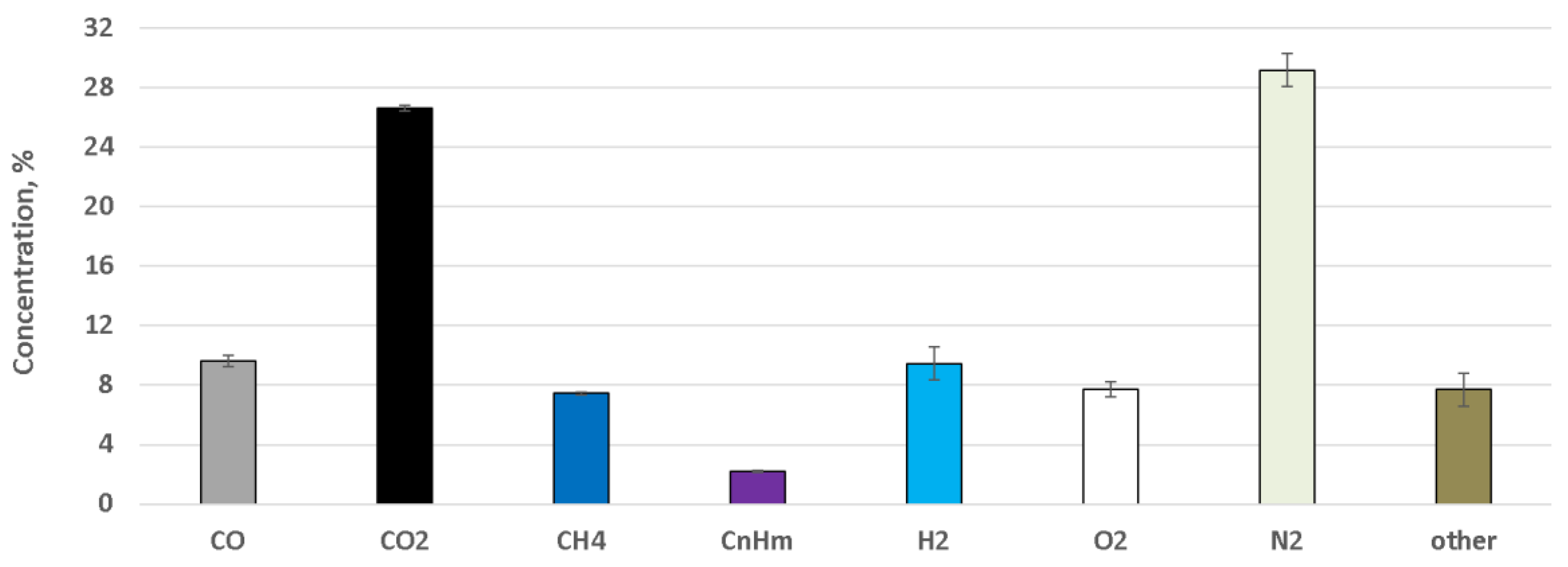
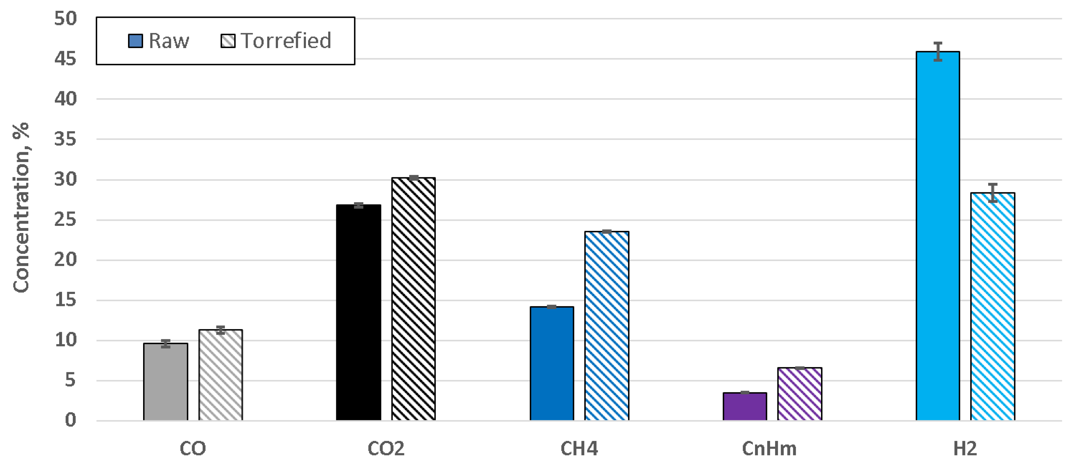
4. Results
5. Discussion
6. Conclusions
- Since the test was performed in an allothermal gasifier, investigation is needed to confirm if the gasification process can be authothermal;
- Tests performed on a pilot-scale gasifier should be performed in order to confirm if such an improvement in tar composition is indeed sufficient to significantly improve the maintenance of such a gasifier and decrease the frequency of the shutdowns.
Author Contributions
Funding
Conflicts of Interest
References
- Werle, S.; Dudziak, M. Analysis of organic and inorganic contaminants in dried sewage sludge and by-products of dried sewage sludge gasification. Energies 2014, 7, 462–476. [Google Scholar] [CrossRef]
- Kacprzak, M.; Neczaj, E.; Fijałkowski, K.; Grobelak, A.; Grosser, A.; Worwag, M.; Rorat, A.; Brattebo, H.; Almås, Å.; Singh, B.R. Sewage sludge disposal strategies for sustainable development. Environ. Res. 2017, 156, 39–46. [Google Scholar] [CrossRef]
- Lee, L.H.; Wu, T.Y.; Shak, K.P.Y.; Lim, S.L.; Ng, K.Y.; Nguyen, M.N.; Teoh, W.H. Sustainable approach to biotransform industrial sludge into organic fertilizer via vermicomposting: A mini-review. J. Chem. Technol. Biotechnol. 2018, 93, 925–935. [Google Scholar] [CrossRef]
- Cieślik, B.M.; Namieśnik, J.; Konieczka, P. Review of sewage sludge management: Standards, regulations and analytical methods. J. Clean. Prod. 2015, 90, 1–15. [Google Scholar] [CrossRef]
- Andersen, A. Disposal and Recycling Routes for Sewage Sludge Part 4: Economic Report; Office for Official Publications of the European Communities: Luxembourg, 2002. [Google Scholar]
- Werle, S.; Wilk, R.K. A review of methods for the thermal utilization of sewage sludge: The Polish perspective. Renew. Energy 2010, 35, 1914–1919. [Google Scholar] [CrossRef]
- GUS, Departament Badań Regionalnych i Środowiska. Ochrona Środowiska 2017; GUS: Warszawa, Poland, 2017; p. 551. [Google Scholar]
- Werle, S. Sewage Sludge-to-Energy Management in Eastern Europe: A Polish Perspective. Ecol. Chem. Eng. S 2015, 22, 459–469. [Google Scholar] [CrossRef]
- Pajak, T. Thermal Treatment as sustainable sewage sludge management. Environ. Prot. Eng. 2013, 39, 41–53. [Google Scholar] [CrossRef]
- Bień, J. Zagospodarowanie komunalnych osadów ściekowych metodami termicznymi. Inż. Ochr. Śr. 2012, 15, 439–450. [Google Scholar]
- Bień, J.; Bień, B. Utilisation of Municipal Sewage Sludge by Thermal Methods in the Face of Storage Disallowing. Inż. Ekol. 2015, 45, 36–43. [Google Scholar] [CrossRef]
- Jurczyk, M.P.; Pająk, T. Initial Operating Experience with the New Polish Waste-to-Energy Plants. In Waste Management; Thomé-Kozmiensky, K.J., Thiel, S., Eds.; TK Verlag: Neuruppin, Germany, 2016. [Google Scholar]
- Cyranka, M.; Jurczyk, M.; Pająk, T. Municipal Waste-to-Energy plants in Poland—Current projects. E3S Web Conf. 2016, 10, 00070. [Google Scholar] [CrossRef]
- Gorazda, K.; Tarko, B.; Wzorek, Z.; Kominko, H.; Nowak, A.K.; Kulczycka, J.; Henclik, A.; Smol, M. Fertilisers production from ashes after sewage sludge combustion—A strategy towards sustainable development. Environ. Res. 2017, 154, 171–180. [Google Scholar] [CrossRef] [PubMed]
- Moscicki, K.J.; Niedzwiecki, L.; Owczarek, P.; Wnukowski, M. Commoditization of biomass: Dry torrefaction and pelletization-a review. J. Power Technol. 2014, 94, 233–249. [Google Scholar]
- Van der Stelt, M.J.C.; Gerhauser, H.; Kiel, J.H.A.; Ptasinski, K.J. Biomass upgrading by torrefaction for the production of biofuels: A review. Biomass Bioenergy 2011, 35, 3748–3762. [Google Scholar] [CrossRef]
- Tumuluru, J.S.; Sokhansanj, S.; Hess, J.R.; Wright, C.T.; Boardman, R.D. A review on biomass torrefcation process and product properties for energy applications. Ind. Biotechnol. 2011, 7, 384–401. [Google Scholar] [CrossRef]
- Nyakuma, B.B.; Magdziarz, A.; Werle, S. Physicochemical, Thermal and Kinetic Analysis of Sewage Sludge. Proc. ECOpole 2016, 10, 473–480. [Google Scholar] [CrossRef]
- Magdziarz, A.; Wilk, M.; Kosturkiewicz, B. Investigation of sewage sludge preparation for combustion process. Chem. Process Eng. Inz. Chem. Proces. 2011, 32, 299–309. [Google Scholar] [CrossRef]
- Magdziarz, A.; Werle, S. Analysis of the combustion and pyrolysis of dried sewage sludge by TGA and MS. Waste Manag. 2014, 34, 174–179. [Google Scholar] [CrossRef]
- Pulka, J.; Wiśniewski, D.; Gołaszewski, J.; Białowiec, A. Is the biochar produced from sewage sludge a good quality solid fuel? Arch. Environ. Prot. 2016, 42, 125–134. [Google Scholar] [CrossRef] [Green Version]
- Poudel, J.; Ohm, T.I.; Lee, S.H.; Oh, S.C. A study on torrefaction of sewage sludge to enhance solid fuel qualities. Waste Manag. 2015, 40, 112–118. [Google Scholar] [CrossRef]
- Poudel, J.; Karki, S.; Gu, J.H.; Lim, Y.; Oh, S.C. Effect of Co-Torrefaction on the Properties of Sewage Sludge and Waste Wood to Enhance Solid Fuel Qualities. J. Residuals Sci. Technol. 2017, 14, 23–36. [Google Scholar] [CrossRef]
- Atienza-Martínez, M.; Fonts, I.; ábrego, J.; Ceamanos, J.; Gea, G. Sewage sludge torrefaction in a fluidized bed reactor. Chem. Eng. J. 2013, 222, 534–545. [Google Scholar] [CrossRef]
- Atienza-Martínez, M.; Mastral, J.F.; Ábrego, J.; Ceamanos, J.; Gea, G. Sewage sludge torrefaction in an auger reactor. Energy Fuels 2015, 29, 160–170. [Google Scholar] [CrossRef]
- Huang, M.; Chang, C.C.; Yuan, M.H.; Chang, C.Y.; Wu, C.H.; Shie, J.L.; Chen, Y.H.; Chen, Y.H.; Ho, C.; Chang, W.R.; et al. Production of torrefied solid bio-fuel from pulp industry waste. Energies 2017, 10, 910. [Google Scholar] [CrossRef]
- Huang, Y.-F.; Sung, H.-T.; Chiueh, P.-T.; Lo, S.-L. Microwave torrefaction of sewage sludge and leucaena. J. Taiwan Inst. Chem. Eng. 2017, 70, 236–243. [Google Scholar] [CrossRef]
- Huang, Y.-F.; Sung, H.-T.; Chiueh, P.-T.; Lo, S.-L. Co-torrefaction of sewage sludge and leucaena by using microwave heating. Energy 2016, 116, 1–7. [Google Scholar] [CrossRef]
- Huang, Y.W.; Chen, M.Q.; Luo, H.F. Nonisothermal torrefaction kinetics of sewage sludge using the simplified distributed activation energy model. Chem. Eng. J. 2016, 298, 154–161. [Google Scholar] [CrossRef]
- Do, T.X.; Lim, Y.; Cho, H.; Shim, J.; Yoo, J.; Rho, K.; Choi, S.-G.; Park, B.-Y. Process modeling and energy consumption of fry-drying and torrefaction of organic solid waste. Dry Technol. 2017, 35, 754–765. [Google Scholar] [CrossRef]
- Pawlak-Kruczek, H.; Krochmalny, K.K.; Wnukowski, M.; Niedzwiecki, L. Slow pyrolysis of the sewage sludge with additives: Calcium oxide and lignite. J. Energy Resour. Technol. 2018, 140. [Google Scholar] [CrossRef]
- Pečkytė, J.; Baltrėnaitė, E. Assessment of heavy metals leaching from (bio) char obtained from industrial sewage sludge. Environ. Prot. Eng. 2015, 7, 399–406. [Google Scholar] [CrossRef]
- Council Decision. Council of the European Union 2003/33/EC—Council Decision establishing criteria and procedures for the acceptance of waste at landfills pursuant to Article 16 of and Annex II to Directive 1999/31/EC. Off. J. Eur. Communities 2003, L 11/27, 27–49. [Google Scholar]
- Wang, N.Y.; Shih, C.H.; Chiueh, P.T.; Huang, Y.F. Environmental effects of sewage sludge carbonization and other treatment alternatives. Energies 2013, 6, 871–883. [Google Scholar] [CrossRef]
- Lasek, J.A.; Kopczyński, M.; Janusz, M.; Iluk, A.; Zuwała, J. Combustion properties of torrefied biomass obtained from flue gas-enhanced reactor. Energy 2017, 119, 362–368. [Google Scholar] [CrossRef]
- Joshi, Y.; Di Marcello, M.; Krishnamurthy, E.; De Jong, W. Packed-Bed Torrefaction of Bagasse under Inert and Oxygenated Atmospheres. Energy Fuels 2015, 29, 5078–5087. [Google Scholar] [CrossRef]
- Uemura, Y.; Saadon, S.; Osman, N.; Mansor, N.; Tanoue, K.I. Torrefaction of oil palm kernel shell in the presence of oxygen and carbon dioxide. Fuel 2015, 144, 171–179. [Google Scholar] [CrossRef]
- Uemura, Y.; Omar, W.; Othman, N.A.; Yusup, S.; Tsutsui, T. Torrefaction of oil palm EFB in the presence of oxygen. Fuel 2013, 103, 156–160. [Google Scholar] [CrossRef]
- Chen, W.H.; Zhuang, Y.Q.; Liu, S.H.; Juang, T.T.; Tsai, C.M. Product characteristics from the torrefaction of oil palm fiber pellets in inert and oxidative atmospheres. Bioresour. Technol. 2016, 199, 367–374. [Google Scholar] [CrossRef] [PubMed]
- Chen, W.H.; Lu, K.M.; Liu, S.H.; Tsai, C.M.; Lee, W.J.; Lin, T.C. Biomass torrefaction characteristics in inert and oxidative atmospheres at various superficial velocities. Bioresour. Technol. 2013, 146, 152–160. [Google Scholar] [CrossRef]
- Lu, K.M.; Lee, W.J.; Chen, W.H.; Liu, S.H.; Lin, T.C. Torrefaction and low temperature carbonization of oil palm fiber and eucalyptus in nitrogen and air atmospheres. Bioresour. Technol. 2012, 123, 98–105. [Google Scholar] [CrossRef]
- Pawlak-Kruczek, H.; Wnukowski, M.; Krochmalny, K.; Kowal, M.; Baranowski, M.; Zgóra, J.; Czerep, M.; Ostrycharczyk, M.; Niedzwiecki, L. The staged thermal conversion of sewage sludge in presence of oxygen. In The Clearwater Clean Coal Conference: Proceedings of the 43rd International Technical Conference on Clean Energy; Sakkestad, B.A., Ed.; Published by Coal Technologies Associates Post Office Box 1130 Louisa, VA 23093 USA: Clearwater, FL, USA, 2018. [Google Scholar]
- Reed, T.B.; Das, A. Handbook of Biomass Downdraft Gasifier Engine Systems; Biomass Energy Foundation: Golden, CO, USA, 1988. [Google Scholar]
- Devi, L.; Ptasinski, K.J.; Janssen, F.J.J.G. A review of the primary measures for tar elimination in biomass gasification processes. Biomass Bioenergy 2002, 24, 125–140. [Google Scholar] [CrossRef]
- Royal Society of Chemistry ChemSpider | Search and Share Chemistry. Available online: http://www.chemspider.com/ (accessed on 23 November 2018).
- Asadullah, M. Biomass gasification gas cleaning for downstream applications: A comparative critical review. Renew. Sustain. Energy Rev. 2014, 40, 118–132. [Google Scholar] [CrossRef]
- Hasler, P.; Nussbaumer, T. Gas cleaning for IC engine applications from fixed bed biomass gasification. Biomass Bioenergy 1999, 16, 385–395. [Google Scholar] [CrossRef]
- Striūgas, N.; Valinčius, V.; Pedišius, N.; Poškas, R.; Zakarauskas, K. Investigation of sewage sludge treatment using air plasma assisted gasification. Waste Manag. 2017. [Google Scholar] [CrossRef] [PubMed]
- Brown, M.D.; Baker, E.G.; Mudge, L.K. Environmental design considerations for thermochemical biomass energy. Biomass 1986, 11, 255–270. [Google Scholar] [CrossRef]
- Bui, T.; Loof, R.; Bhattacharya, S.C. Multi-stage reactor for thermal gasification of wood. Energy 1994, 19, 397–404. [Google Scholar] [CrossRef]
- Werle, S. Sewage sludge gasification: Theoretical and experimental investigation. Environ. Prot. Eng. 2013, 39, 25–32. [Google Scholar] [CrossRef]
- Schweitzer, D.; Gredinger, A.; Schmid, M.; Waizmann, G.; Beirow, M.; Spörl, R.; Scheffknecht, G. Steam gasification of wood pellets, sewage sludge and manure: Gasification performance and concentration of impurities. Biomass Bioenergy 2018, 111, 308–319. [Google Scholar] [CrossRef]
- Werle, S. Numerical analysis of the combustible properties of sewage sludge gasification gas. Chem. Eng. Trans. 2015, 1021–1026. [Google Scholar] [CrossRef]
- Werle, S.; Dudziak, M. Evaluation of the possibility of the sewage sludge gasification gas use as a fuel. Ecol. Chem. Eng. S 2016, 23, 229–236. [Google Scholar] [CrossRef] [Green Version]
- Szwaja, S.; Kovacs, V.B.; Bereczky, A.; Penninger, A. Sewage sludge producer gas enriched with methane as a fuel to a spark ignited engine. Fuel Process. Technol. 2013, 110, 160–166. [Google Scholar] [CrossRef]
- Werle, S. Impact of feedstock properties and operating conditions on sewage sludge gasification in a fixed bed gasifier. Waste Manag. Res. 2014, 32, 954–960. [Google Scholar] [CrossRef]
- Calvo, L.F.; García, A.I.; Otero, M. An experimental investigation of sewage sludge gasification in a fluidised bed reactor. Sci. World J. 2013. [Google Scholar] [CrossRef] [PubMed]
- Akkache, S.; Hernández, A.B.; Teixeira, G.; Gelix, F.; Roche, N.; Ferrasse, J.H. Co-gasification of wastewater sludge and different feedstock: Feasibility study. Biomass Bioenergy 2016, 89, 201–209. [Google Scholar] [CrossRef]
- Reed, G.P.; Paterson, N.P.; Zhuo, Y.; Dugwell, D.R.; Kandiyoti, R. Trace element distribution in sewage sludge gasification: Source and temperature effects. Energy Fuels 2005, 19, 298–304. [Google Scholar] [CrossRef]
- Judex, J.W.; Gaiffi, M.; Burgbacher, H.C. Gasification of dried sewage sludge: Status of the demonstration and the pilot plant. Waste Manag. 2012, 32, 719–723. [Google Scholar] [CrossRef] [PubMed]
- Kokalj, F.; Arbiter, B.; Samec, N. Sewage sludge gasification as an alternative energy storage model. Energy Convers. Manag. 2017, 149, 738–747. [Google Scholar] [CrossRef]
- Huang, Y.W.; Chen, M.Q.; Li, Q.H.; Xing, W. Hydrogen-rich syngas produced from co-gasification of wet sewage sludge and torrefied biomass in self-generated steam agent. Energy 2018, 161, 202–213. [Google Scholar] [CrossRef]
- Prins, M.J.; Ptasinski, K.J.; Janssen, F.J.J.G. More efficient biomass gasification via torrefaction. Energy 2006, 31, 3458–3470. [Google Scholar] [CrossRef]
- Dudyński, M.; Van Dyk, J.C.; Kwiatkowski, K.; Sosnowska, M. Biomass gasification: Influence of torrefaction on syngas production and tar formation. Fuel Process. Technol. 2015, 131, 203–212. [Google Scholar] [CrossRef]
- Tic, W.; Guziałowska-Tic, J.; Pawlak-Kruczek, H.; Woźnikowski, E.; Zadorożny, A.; Niedźwiecki, Ł.; Wnukowski, M.; Krochmalny, K.; Czerep, M.; Ostrycharczyk, M.; et al. Novel Concept of an Installation for Sustainable Thermal Utilization of Sewage Sludge. Energies 2018, 11, 748. [Google Scholar] [CrossRef]
- Pawlak-Kruczek, H.; Krochmalny, K.; Mościcki, K.; Zgóra, J.; Czerep, M.; Ostrycharczyk, M.; Niedźwiecki, Ł. Torrefaction of Various Types of Biomass in Laboratory Scale, Batch-Wise Isothermal Rotary Reactor and Pilot Scale, Continuous Multi-Stage Tape Reactor. Eng. Prot. Environ. 2017, 20, 457–472. [Google Scholar] [CrossRef]
- Weber, K.; Heuer, S.; Quicker, P.; Li, T.; Løvås, T.; Scherer, V. An Alternative Approach for the Estimation of Biochar Yields. Energy Fuels 2018. [Google Scholar] [CrossRef]
- Nhuchhen, D.; Basu, P.; Acharya, B. A Comprehensive Review on Biomass Torrefaction. Int. J. Renew. Energy Biofuels 2014, 2014, 506376. [Google Scholar] [CrossRef]
- Esseyin, A.E.; Steele, P.H.; Pittman, C.U., Jr. Current trends in the production and applications Torrefied Wood/Biomass—A review. Bioresources 2015, 10, 8812–8858. [Google Scholar] [CrossRef]
- Chew, J.J.; Doshi, V. Recent advances in biomass pretreatment—Torrefaction fundamentals and technology. Renew. Sustain. Energy Rev. 2011, 15, 4212–4222. [Google Scholar] [CrossRef]
- Saeed, M.A.; Andrews, G.E.; Phylaktou, H.N.; Gibbs, B.M.; Niedzwiecki, L.; Walton, R. Explosion and Flame Propagation Properties of Coarse Wood: Raw and Torrefied. In Proceedings of the Eighth International Seminar on Fire & Explosion Hazards (ISFEH8); Choa, J., Molkov, V., Sunderland, P., Tamanini, F., Torero, J., Eds.; USTC Press: Hefei, China, 2016; pp. 579–588. [Google Scholar]


| Test | Symbol | Value | Unit | Standard Procedure | |
|---|---|---|---|---|---|
| Raw | Torrefied | ||||
| Moisture content 1 | MC | 26.2 | 2.30 | % | EN ISO 18134-2:2015 |
| Volatile matter content | VM d | 58.1 | 44.40 | % | EN 15148:2009 |
| Ash content | A d | 32.5 | 45.67 | % | EN ISO 1822:2015 |
| Higher heating value | HHV | 15,700 | 10,300 | kJ/kg | EN 14918:2009 |
| Lower heating value 2 | LHV | 10,939 | 10,006 | kJ/kg | EN 14918:2009 |
| Carbon content | C d | 27.89 | 15.83 | % | EN ISO 16948:2015 |
| Hydrogen content | H d | 6.67 | 2.92 | % | EN ISO 16948:2015 |
| Nitrogen content | N d | 4.36 | 4.18 | % | EN ISO 16948:2015 |
| Sulfur content | S d | 0.29 | 0.27 | % | EN ISO 16994:2016 |
| Oxygen content | O d | 28.80 | 31.13 | % | EN ISO 16993:2015 |
| Characteristic Temperature | Raw Sewage Sludge | Torrefied Sewage Sludge | Unit |
|---|---|---|---|
| Deformation temperature (DT) | 1000 | 1010 | °C |
| Sphere temperature (ST) | 1020 | 1050 | °C |
| Hemisphere temperature (HT) | 1110 | 1110 | °C |
| Flow temperature (FT) | 1210 | 1210 | °C |
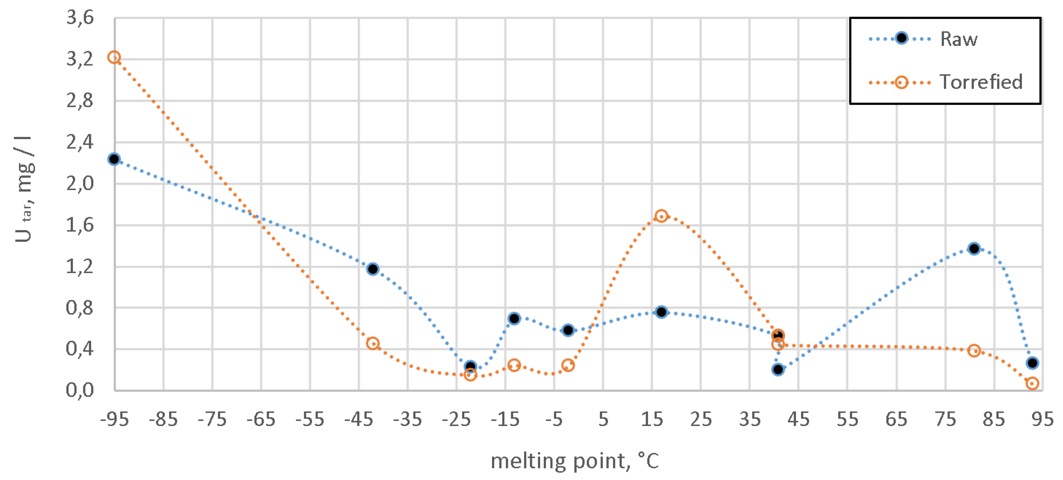
| Compound | Form. | Boil. Point | Melt. Point | Avg. Mass | Relative Area of the Peak 2 | |||
|---|---|---|---|---|---|---|---|---|
| Raw | Torrefied | |||||||
| Value | SD 1 | Value | SD 1 | |||||
| °C | °C | Da | % | % | % | % | ||
| Toluene | C7H8 | 111 | −95 | 92.14 | 21.41 | 0.64 | 32.60 | 0.39 |
| Propiononitrile | C3H5N | 97 | −92 | 55.08 3 | 0.14 | 0.03 | 1.11 | 0.02 |
| 2-Methylpyridine | C6H7N | 128 | −70 | 93.12 | 1.40 | 0.09 | 1.64 | 0.02 |
| o-Xylene | C8H10 | 140 | −48 | 106.16 | 0.10 | 0.03 | 1.40 | 0.02 |
| 3-Methyl-1H-pyrrole | C5H7N | 144 | −48 | 81.12 | 0.12 | 0.01 | 1.40 | 0.03 |
| Pyridine | C5H5N | 115 | −42 | 79.10 | 6.23 | 0.21 | 3.12 | 0.03 |
| Thiophene | C4H4S | 84 | −38 | 84.14 | 2.01 | 0.11 | 0.26 | 0.01 |
| 2-Methyl-1H-pyrrole | C5H7N | 147 | −36 | 81.12 | 0.51 | 0.01 | 0.69 | 0.02 |
| Styrene | C8H8 | 145 | −31 | 104.15 | 4.54 | 0.26 | 7.26 | 0.05 |
| 3-Methylbenzonitrile | C8H7N | 210 | −25 | 117.15 | 0.10 | 0.01 | - 5 | - |
| Benzeneacetonitrile | C8H7N | 234 | −24 | 117.15 | 0.23 | 0.01 | 0.30 | 0.01 |
| 1H-Pyrrole | C4H5N | 130 | −23 | 67.09 3 | 2.71 | 0.11 | 3.84 | 0.02 |
| 2-Methylnaphthalene | C11H10 | 242 | −22 | 142.20 | 2.24 | 0.09 | 1.93 | 0.03 |
| 1-Methylnaphthalene | C11H10 | 242 | −22 | 142.20 | 1.41 | 0.07 | 1.63 | 0.04 |
| 1-Benzofuran | C8H6O | 174 | −18 | 118.13 | 0.40 | 0.02 | 0.34 | 0.01 |
| Quinoline | C9H7N | 237 | −15 | 129.16 | 3.32 | 0.07 | 0.91 | 0.01 |
| Benzonitrile | C7H5N | 191 | −13 | 103.12 | 5.32 | 0.15 | 2.86 | 0.03 |
| 2-Methylbenzonitrile | C8H7N | 205 | −13 | 117.14 | 0.31 | 0.02 | 0.11 | 0.01 |
| 1H-Indene | C9H8 | 181 | −2 | 116.16 | 4.83 | 0.21 | 2.68 | 0.02 |
| 2-Methylquinoline | C10H9N | 247 | −2 | 143.18 | 0.21 | 0.01 | 0.13 | 0.01 |
| m-Cresol | C7H8O | 203 | 11 | 108.12 | - | - | 0.40 | 0.07 |
| Acetic acid | C2H4O2 | 118 | 17 | 60.05 3 | 0.23 | 0.05 | 3.51 | 0.01 |
| 3-Methylpyridine | C6H7N | 144 | 18 | 93.13 | 0.51 | 0.03 | 0.61 | 0.01 |
| Isoquinoline | C9H7N | 242 | 26 | 129.16 | 0.80 | 0.01 | 0.12 | 0.01 |
| 4-Methylbenzonitrile | C8H7N | 218 | 28 | 117.15 | 0.22 | 0.01 | 0.13 | 0.01 |
| Phenol | C6H6O | 182 | 41 | 94.11 | 1.81 | 0.07 | 5.56 | 0.12 |
| p-Cresol | C7H8O | 202 | 41 | 108.14 | 0.43 | 0.02 | 3.88 | 0.07 |
| 1H-Indole | C8H7N | 254 | 53 | 117.15 | 4.03 | 0.15 | 2.68 | 0.04 |
| 3-Pyridinamine | C5H6N2 | 250 | 62 | 94.11 | 0.21 | 0.03 | 1.16 | 0.01 |
| 2-Naphthonitrile | C11H7N | 157 | 67 | 153.18 | 0.72 | 0.01 | - | - |
| Naphthalene | C10H8 | 218 | 81 | 128.17 | 22.00 | 0.60 | 8.19 | 0.12 |
| Acenaphthylene | C12H8 | 280 | 93 | 152.19 | 4.21 | 0.09 | 1.05 | 0.01 |
| Phenanthrene | C14H10 | 338 | 100 | 178.23 | 3.13 | 0.01 | 0.45 | 0.03 |
| 9H-Fluorene | C13H10 | 295 | 115 | 166.22 | 0.70 | 0.02 | - | - |
| 5,5-Dimethyl-2,4-imidazolidinedione | C5H8N2 | n.a. 4 | 175 | 128.13 | 0.51 | 0.05 | 4.65 | 0.13 |
| 3,3′-Sulfanediyldipropanenitrile | C6H8N2 | n.a. | n.a. | 140.21 | 2.41 | 0.16 | 0.62 | 0.04 |
| 2-Benzothiophene | C8H6S | n.a. | n.a. | 134.20 | 1.14 | 0.04 | 0.20 | 0.01 |
| Compound | Form. | Boil. Point | Melt. Point | Avg. Mass | Concentration in the Producer Gas | |||
|---|---|---|---|---|---|---|---|---|
| Raw | Torrefied | |||||||
| Value | SD | Value | SD | |||||
| °C | °C | Da | mg/m3 | mg/m3 | mg/m3 | mg/m3 | ||
| Toluene | C7H8 | 111 | −95 | 92.14 | 2229.1 | 91.4 | 3211.0 | 61.0 |
| Pyridine | C5H5N | 115 | −42 | 79.10 | 1170.0 | 37.4 | 453.8 | 3.7 |
| 1-Methylnaphthalene | C11H10 | 242 | −22 | 142.20 | 225.6 | 7.7 | 149.4 | 3.5 |
| Benzonitrile | C7H5N | 191 | −13 | 103.12 | 688.2 | 18.2 | 243.0 | 3.5 |
| 1H-Indene | C9H8 | 181 | −2 | 116.16 | 574.7 | 25.3 | 243.6 | 0.9 |
| Acetic acid | C2H4O2 | 118 | 17 | 60.05 1 | 752.3 | 32.0 | 1680.3 | 5.2 |
| Phenol | C6H6O | 182 | 41 | 94.11 | 521.7 | 10.7 | 531.0 | 11.8 |
| p-Cresol | C7H8O | 202 | 41 | 108.14 | 198.4 | 3.7 | 444.9 | 7.9 |
| Naphthalene | C10H8 | 218 | 81 | 128.17 | 1367.6 | 47.7 | 384.7 | 8.5 |
| Acenaphthylene | C12H8 | 280 | 93 | 152.19 | 263.9 | 6.4 | 62.0 | 1.5 |
© 2019 by the authors. Licensee MDPI, Basel, Switzerland. This article is an open access article distributed under the terms and conditions of the Creative Commons Attribution (CC BY) license (http://creativecommons.org/licenses/by/4.0/).
Share and Cite
Pawlak-Kruczek, H.; Wnukowski, M.; Niedzwiecki, L.; Czerep, M.; Kowal, M.; Krochmalny, K.; Zgóra, J.; Ostrycharczyk, M.; Baranowski, M.; Tic, W.J.; et al. Torrefaction as a Valorization Method Used Prior to the Gasification of Sewage Sludge. Energies 2019, 12, 175. https://doi.org/10.3390/en12010175
Pawlak-Kruczek H, Wnukowski M, Niedzwiecki L, Czerep M, Kowal M, Krochmalny K, Zgóra J, Ostrycharczyk M, Baranowski M, Tic WJ, et al. Torrefaction as a Valorization Method Used Prior to the Gasification of Sewage Sludge. Energies. 2019; 12(1):175. https://doi.org/10.3390/en12010175
Chicago/Turabian StylePawlak-Kruczek, Halina, Mateusz Wnukowski, Lukasz Niedzwiecki, Michał Czerep, Mateusz Kowal, Krystian Krochmalny, Jacek Zgóra, Michał Ostrycharczyk, Marcin Baranowski, Wilhelm Jan Tic, and et al. 2019. "Torrefaction as a Valorization Method Used Prior to the Gasification of Sewage Sludge" Energies 12, no. 1: 175. https://doi.org/10.3390/en12010175