Article

An Irregular Current Injection Islanding Detection Method Based on an Improved Impedance Measurement Scheme

1
Department of Electrical Engineering, Tsinghua University, Beijing 100084, China
2
Department of Engineering, Durham University, Durham DH1 3LE, UK
*
Author to whom correspondence should be addressed.
Energies 2018, 11(9), 2474; https://doi.org/10.3390/en11092474
Submission received: 17 August 2018 / Revised: 8 September 2018 / Accepted: 8 September 2018 / Published: 17 September 2018

Abstract

:
One class of islanding detection methods, known as impedance measurement-based methods and voltage change monitoring-based methods, are implemented through injecting irregular currents into the network, for which reason they are defined in this paper as irregular current injection methods. This paper indicates that such methods may be affected by distributed generation (DG) unit cut-in events. Although the network impedance change can still be used as a judgment basis for islanding detection, the general impedance measurement scheme cannot separate island events from DG unit cut-in events in multi-DG operation. In view of this, this paper proposes a new islanding detection method based on an improved impedance measurement scheme, i.e., dynamic impedance measurement, which will not be affected by DG unit cut-in events and can further assist some other equipment in islanding detection. The simulations and experiments verify the stated advantages of the new islanding detection method.

1. Introduction

Due to the vigorous upward trend in the need for clean energy, Distributed generation (DG) has flourished, and its related technologies have attracted more and more attention. As an essential feature of DG, islanding detection has been the topic of many studies. A series of islanding detection methods have been developed, which are generally divided into remote methods and local methods. The local methods in turn include active methods and passive methods. The active methods attract more studies and applications due to their low cost and reliability. The active methods that are based on impedance measurement and voltage change monitoring are collectively referred to as irregular current injection islanding detection methods in this paper, as all of them are realized by injecting irregular currents, e.g., high frequency currents, into a network, and this paper will focus on such methods.
With regard to the irregular current injection methods, the judgment on an island event is based on the changes of the irregular voltages excited by the injected irregular currents. On the basis of this idea, the irregular voltage changes were directly monitored in [1,2,3,4,5,6,7,8], whereas the network impedance was further calculated in [9,10,11] and the unbalance factor of the terminal voltage of DG units was calculated in [12]. Moreover, the injected irregular currents are also different in these references. High frequency currents were adopted in [1,2,3,4,9,10,11]; asymmetric sub-harmonics current was used in [5]; a pulse current was adopted in [6]; and negative sequence currents were adopted in [7,8,12]. In contrast, irregular voltage injection was proposed in [13,14,15,16,17] for islanding detection.
In addition, many other types of methods are also highly effective. The methods proposed in [18,19] belong to another classic type of islanding detection methods, i.e., frequency shift methods, which perturbed current phase and reactive current, respectively; the Sandia Frequency Shift (SFS) method was improved in [20], which is a classic active method, by decreasing the positive feedback gain to reduce the effect on system stability; an idea of grid stiffness measurement was proposed in [21], by which an island is identified according to the stiffness change; the method in [22] periodically perturbed the reactive current and confirmed that there is a frequency undulation in an island condition, which is seen as a criterion of islanding; a hybrid method based on the SFS method and rate of change of frequency (ROCOF) relay is proposed in [23], by which a smaller non-detection zone (NDZ) is achieved; two passive methods were reported in [24] and [25], respectively, the former of which employed the signal processing theory and measured the network impedance passively, and the latter of which estimated the voltage and impedance parameters of a linear Thevenin-like model to detect an island; a wavelet packet transform was used in [26] to extract the signal for islanding detection; the method in [27] was a remote method, which took advantage of the phasor measurement unit to collect the evidence of an island; and remote communication was also utilized in [28] to facilitate the performance of islanding detection.
Although the methods proposed in the above literature have been declared reliable, some practical problems still exist for existing irregular current injection methods, one of which is the misjudgment problem resulting from DG unit cut-in events. The existing methods are based on the surge of measured irregular voltage. However, both island events and large power DG unit cut-in events can bring about such surge. The existing methods cannot distinguish between these two events by means of the general impedance measurement scheme, i.e., static impedance measurement. The following will briefly introduce this problem:
(a) Introduction of irregular current injection methods: Inverter-based DG is currently very popular, and thus the analyses in this paper are based on this type of DG. An inverter-based DG diagram is shown in Figure 1.
In a grid-connected condition (i.e., with the switch Sg turned on), the equivalent input network impedance seen from the DG unit (hereinafter referred to as network impedance) is:
Zeq(grid) = Zg//Zl
where Zg and Zl are grid impedance (i.e., Rg + jωLg) and load impedance, respectively. Since |Zg| is much smaller than |Zl| over a certain frequency range [5,29], |Zeq(grid)| is close to |Zg|.
In an island condition (i.e., with the switch Sg turned off), the network impedance is:
Zeq(island) = Zl
According to the analyses above, Inequality (1) is established:
|Zeq(grid)| < |Zeq(island)|
In many cases, the difference between |Zeq(grid)| and |Zeq(island)| is obvious. Accordingly, a network impedance surge can be used as the indicator of an island just formed.
The network impedance is calculated by means of the irregular voltages and currents extracted from the measured voltages and currents at the terminal of the DG units. The types of the irregular voltages and currents can be of a high frequency positive sequence, low frequency positive sequence, high frequency negative sequence, fundamental frequency negative sequence and low frequency negative sequence. Such voltages and currents inherent in the grid are small and uncontrollable. To measure the network impedance accurately, such voltages or currents are injected by the DG units. By comparison, irregular current injections are more common in the literature, from which the irregular current injection islanding detection method derives.
The irregular current injection method involves injecting irregular currents into a network, and then the changes of the resultant irregular voltage at the terminal of a DG unit can reflect the network impedance changes. Consequently, considering the relationship shown in Inequality (1), there will be a surge of the irregular voltage (magnitude) when an island event occurs. From this, the changes of some quantities, including the irregular voltages, the total harmonic distortion (THD) and unbalance factor of the terminal voltages of DG units, the network impedance, and the correlation between the irregular currents and voltages, which in fact reflect the irregular voltage changes, can be used as the judgment basis of island events.
The above analysis indicates that for an irregular current injection method the criterion of an island event is essentially the irregular voltage surge. Therefore, any event causing an irregular voltage surge in a grid-connected condition may result in a nuisance tripping.
(b) DG Unit Cut-in: Figure 2 shows a scenario where there are n running DG units and all the presented currents/voltages are the same type of irregular currents/voltages. When DGn+1 unit is cut-in, the irregular current I DG ( n + 1 ) will be accumulated to the former aggregate current I agg , which will thereby cause an increase of the irregular voltage Uir. The increase of Uir is comparable to what occurs after an island event if IDG(n+1) is large enough. Considering that generally there is no communication between the DG units, the former running DG units cannot distinguish this event from an island event, for which reason a misjudgment is inevitable.
(c) DG Unit Cut-out: As shown in Figure 2, if one of the running DG units is cut-out, as above, Iagg and Uir will decrease, which may not affect the islanding detection.
(d) Load Cut-in/Cut-out: For a strong grid, the grid impedance is much smaller than the load impedance, and thus a load cut-in/cut-out has little influence on the network impedance, for which reason Uir has little change and there is no response to it. A study based on a weak grid is much more complex, which is not the interest of this paper and will not be analyzed.
In conclusion, DG unit cut-in events may affect the irregular current injection methods, especially when large irregular currents are injected by the DG unit cut-in, by which a misjudgment is very likely to happen. On account of this, this paper will study this problem and propose a new method based on an improved impedance measurement scheme.
This paper is organized as follows: Section 2 reveals the disadvantage of general impedance measurement scheme; Section 3 proposes a new islanding detection method; the simulations in Section 4 and experiments in Section 5 verify the performance of the proposed method; and finally, conclusions are drawn.

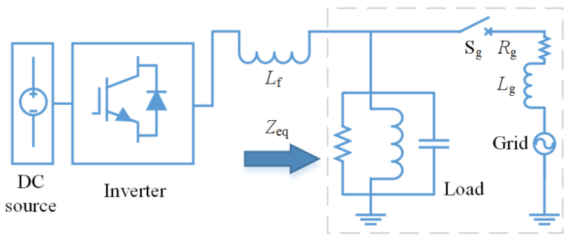
2. Impedance Measurement

By observing Figure 2 it can be found that the network impedance does not change when a DG unit is cut-in in a grid-connected condition, whereas it is just the opposite when an island event occurs. In this case, why not use the network impedance change to determine an island? Theoretically, this is entirely possible, but the DG units have been unable to detect the network impedance in multi-DG operation, which includes the situation where a new DG unit has been cut-in. The analysis is as follows.
As shown in Figure 2, the DG units share the terminal voltage. Considering that |Zg| is much smaller than |Zl|, in a grid-connected condition, U ir can be expressed as:
U ir = ( I DG 1 + + I DG   i + + I DG   n ) Z eq ( grid ) + U s _ ir  
where U s _ ir is the inherent harmonic voltage in the source (see Figure 2). Since Us_ir is relatively small, the following analysis will ignore it.
For the DGi (0 < i< n + 1) unit, the general approach is to calculate the static impedance as the network impedance, as shown below:
Z s = U ir I DG   i  
By substituting Equation (2) into the above equation, the initial static impedance detected by DGi unit is:
Z s 0 = ( 1 + I DG 1 + + I DG ( i 1 ) + I DG ( i + 1 ) + + I DG   n I DG   i ) Z eq ( grid )  
Obviously, even though U s _ ir is not considered, the static impedance is the network impedance only in single-DG operation, not in multi-DG operation where it should be larger than the network impedance and the measured value of each DG unit is different.
If a new unit called DGn+1 unit is cut-in at this time, the static impedance will be:
Z s _ cutin = ( 1 + I DG 1 + + I DG ( i 1 ) + I DG ( i + 1 ) + + I DG   n + I DG ( n + 1 ) I DG   i ) Z eq ( grid )  
Therefore, the relationship below can be derived from Equations (3) and (4):
|Zs_cutin| > |Zs0|
On the other hand, if an island event occurs in the network shown in Figure 2, as above, the static impedance will be:
Z s _ isl = ( 1 + I DG 1 + + I DG ( i 1 ) + I DG ( i + 1 ) + + I DG   n I DG   i ) Z eq ( island )  
By combining Expressions (1), (3) and (6), the relationship below is true:
|Zs_isl| > |Zs0|
Inequalities (5) and (7) reveal that there will be an impedance surge after both a DG unit cut-in event and an island event. Consequently, existing irregular current injection methods may treat both the two events as island events for they only deem a static impedance surge as the islanding criterion. This misjudgment is exactly the problem with the existing methods. For this reason, this paper will propose an improved impedance measurement scheme to distinguish between these two events.

3. New Irregular Current Injection Islanding Detection Method

3.1. Improved Impedance Measurement Scheme

Section 2 has pointed out that Uir will increase after both a DG unit cut-in event and an island event. If the DG units immediately increase the output irregular currents by a certain percentage, noted as k I DG   i , when Uir goes into a steady state, Uir will increase again. The whole process is shown in Figure 3, where Uir starts to increase at t1 until it stabilizes at Uir1 at t2; then the DG units increase the irregular currents at t3, which is followed by a new increase of Uir until Uir stabilizes at Uir2 at t4.
In this way, an improved impedance measurement scheme using dynamic impedance will be demonstrated below. A dynamic impedance Zd can be expressed as:
Z d = U ir 2 U ir 1 k I DG   i  

3.1.1. A DG Unit Cut-In Event in a Grid-Connected Condition

According to Figure 2 and Figure 3, it is supposed that the DGn+1 unit is cut-in at t1, and then the equations below are true:
U ir 1 = ( I DG 1 + + I DG   i + + I DG   n + I DG ( n + 1 ) ) Z eq ( grid )  
U ir 2 = ( ( 1 + k ) I DG 1 + + ( 1 + k ) I DG   i + + ( 1 + k ) I DG   n + I DG ( n + 1 ) ) Z eq ( grid )  
Accordingly, by referencing Equation (8) the DGi unit can obtain a dynamic impedance:
Z d _ cutin = ( 1 + I DG 1 + + I DG ( i 1 ) + I DG ( i + 1 ) + + I DG   n I DG   i ) Z eq ( grid )  
By comparing the above equation with Equation (3), we have:
|Zd_cutin| = |Zs0|

3.1.2. An Island Event

As above, it is supposed that an island event occurs at t1, and the following equations are established:
U ir 1 = ( I DG 1 + + I DG   i + + I DG   n ) Z eq ( island )  
U ir 2 = ( ( 1 + k ) I DG 1 + + ( 1 + k ) I DG   i + + ( 1 + k ) I DG   n ) Z eq ( island )  
The dynamic impedance is:
Z d _ isl = ( 1 + I DG 1 + + I DG ( i 1 ) + I DG ( i + 1 ) + + I DG   n I DG   i ) Z eq ( island )  
In the same way, by comparing the above equation with Equations (3) and (6), there is:
|Zd_isl| = |Zs_isl| > |Zs0|
On the basis of the analyses above, it is found that although the improved impedance measurement scheme still cannot detect the network impedance, the relationship between the initial static impedance and the dynamic impedance, i.e., Expressions (10) and (12), can be used to distinguish island events from DG unit cut-in events. The proposed method in this paper exploits this advantage and can thereby solve the mentioned problem with existing irregular current injection methods. In other words, for a DG unit, an island can be determined only when the relationship below is established.
|Zd| > |Zs0|
Additionally, in reality, a DG unit does not have to wait until the Uir becomes stable to calculate the |Zd|. When the command of increasing the irregular current is issued, i.e., t3 in Figure 3, it can begin to continuously calculate according to Equation (8), where the U ir 2 is replaced by the latest measured U ir . Although the resulting |Zd| may be inaccurate, it can be used for judgment like the true value. More importantly, the islanding detection will be faster by following this mode.

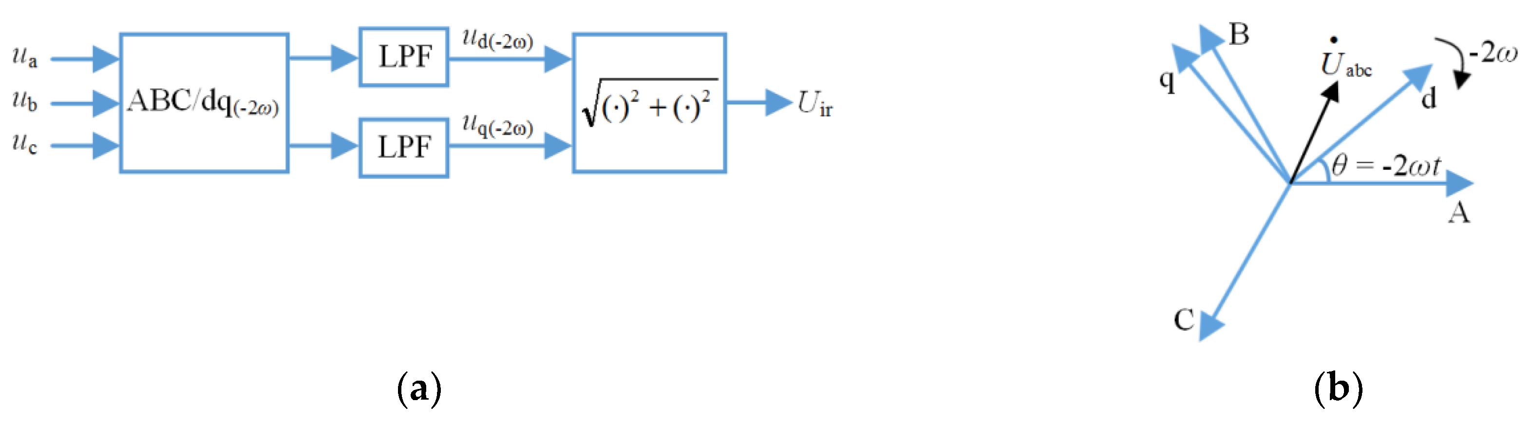
3.2. Irregular Current and Signal Extraction

Generally, to mitigate the adverse influence of some other factors on islanding detection, the type of the injected irregular current should be different from that in the network as much as possible. Thus, this paper injects negative sequence second harmonic currents into a three-phase network. To minimize the damage to power quality, comply with the relevant grid codes and take into account the control accuracy of a DG unit, initially second harmonic currents that are equivalent to 0.5% of the rated current of the DG unit are injected, and when calculating the dynamic impedance, k is set to 0.6 to make the increased second harmonic currents remain within the 1% limit [30]. Meanwhile, a strict restriction on the injected irregular currents can bring about a more transient current/voltage transition, i.e., smaller t2t1 and t4t3 in Figure 3, which is conducive to the rapidity of an islanding detection. To calculate the impedance, the magnitude of the negative sequence second harmonic voltages is needed, which is extracted by the algorithm shown in Figure 4a. According to this algorithm, first, the terminal voltages of a DG unit are converted from the three-phase stationary reference frame to the two-phase double synchronous frequency reverse rotating (i.e., clockwise) reference frame, i.e., ABC to dq(−2ω) reference frame, which is shown in Figure 4b and can be specifically expressed as:
( u d u q ) = 2 3 ( cos ( 2 ω t ) cos ( 2 ω t 2 π / 3 ) cos ( 2 ω t + 2 π / 3 ) sin ( 2 ω t ) sin ( 2 ω t 2 π / 3 ) sin ( 2 ω t + 2 π / 3 ) ) ( u a u b u c )  
where ω is the fundamental frequency.
Then the negative sequence second harmonic component will be present as constants in the rotating reference frame while the other components will be present as fluctuation quantities. Next, two low pass filters (LPFs) are used to filter out the fluctuation quantities; and finally, the magnitude of the negative sequence second harmonic voltages is obtained by synthesizing the outputs of the filters. Additionally, in order not to aggravate the computational burden on the system, the magnitude of the negative sequence second harmonic currents can be represented by the reference value rather than extracted from the actual currents.

3.3. Assisting Other Equipment to Detect an Island

The equipment that can only detect an island passively usually observes whether the harmonic voltage or the frequency is out of their limits. To assist such equipment to detect an island, the DG unit mentioned in this paper can reduce the restriction on IDG to boost the Uir, i.e., the harmonic voltage, once an island is determined. Specifically, IDG can be set as follows:
IDG = 5% I1, if Uir < 2% U1
where U1 and I1 are the rated voltage and rated current of the DG unit, respectively; and 2% and 5% are the limits of second harmonic voltage and current THD in the Chinese grid codes, respectively. In an island condition, although a larger IDG can result in a larger Uir, IDG should not be set to a large value, or the follow-up operation may be affected, e.g., switched to intentional islanding mode.
In addition, an islanding detection must be finished within 2 s [30]. Thus, the process of boosting Uir above should not last too long. In other words, the time from the initial increase of the negative sequence second harmonic voltages (i.e., t1 in Figure 3) to cease to energize the network should not be more than 2 s.
Due to the above limitation, the proposed method can somewhat assist but cannot ensure that the other equipment detects the island. The implementation of the proposed method is summarized in Figure 5, where k1 and k2 are the thresholds; Tlim is the tolerable duration of a DG unit in an island condition and Tlim < 2 s; and m is the sampling serial number.

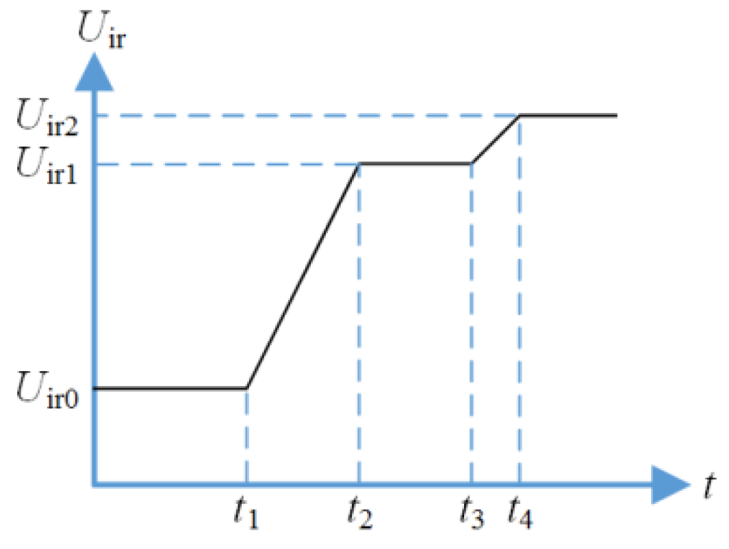
3.4. Selection of k1 and k2

As shown in Figure 5, k1 is the threshold used to decide whether to measure the dynamic impedance, for which reason it will not directly affect the judgment on an event. To enhance the sensitivity of the proposed method, k1 can be set as small as possible, as long as it does not cause frequent dynamic impedance measurement due to the fluctuation of Uir. Actually, during a steady state, Uir is smooth due to the LPFs in Figure 4a. Thus, k1 can be a value close to 1 and is set to 2 in this paper. In a practical system, maybe some DG units still employ the existing irregular current injection methods, including those DG units that cannot implement the mentioned dynamic impedance measurement. Thus, there will be the following two scenarios, different from the demonstration in Section 3.1.

3.4.1. An Event Followed by a Relatively Small Increase of Uir

In this scenario, the DG units employing the existing methods will not act, whereas the ones employing the proposed method may begin islanding detection. Then, the curve of Uir is still like that shown in Figure 3, while the Uir2 is different and can be expressed as:
U ir 2 = { ( ( 1 + k ) I DG 1 + + ( 1 + k ) I DG   i + + ( 1 + k ) I DG   p + I DG ( p + 1 ) + + I DG ( n + 1 ) ) Z eq ( grid ) ,   for   a   DG   unit   cut - in   event ( ( 1 + k ) I DG 1 + + ( 1 + k ) I DG   i + + ( 1 + k ) I DG   p + I DG ( p + 1 ) + + I DG   n ) Z eq ( island ) ,   for   an   island   event  
where it is supposed that only the first p DG units in Figure 2 employ the proposed method and pn. By combining Equations (8), (9), (11) and (13), the dynamic impedance below can be obtained.
{ Z d _ cutin = ( 1 + I DG 1 + + I DG ( i 1 ) + I DG ( i + 1 ) + + I DG   p I DG   i ) Z eq ( grid ) Z d _ isl = ( 1 + I DG 1 + + I DG ( i 1 ) + I DG ( i + 1 ) + + I DG   p I DG   i ) Z eq ( island )  
According to Equations (3), (6) and (14), the relationships below are true:
{ | Z eq ( grid ) |     | Z d _ cutin |     | Z s 0 | | Z eq ( island ) |     | Z d _ isl |     | Z s _ isl |  
The terms in the upper inequality of (15) are successively smaller than those in the lower inequality. Hence, for the threshold Zth used to distinguish between Zd_cutin and Zd_isl, if |Zd| < |Zth|, Zd represents Zd_cutin and a DG unit cut-in event is determined, otherwise an island event is determined. If |Zs0| ≤ |Zeq(island)|, |Zth| can be a value between |Zs0| and |Zeq(island)|, otherwise, the selection of Zth is difficult. On the other hand, Zs0 can be obtained while Zeq(island) cannot, and consequently Zth can only be selected according to Zs0. If Zth is set as |Zth| > |Zs0|, DG unit cut-in events will not be misjudged. Due to the lack of knowledge of Zeq(island), no value for Zth can ensure that island events are not misjudged; however, a smaller |Zth| can reduce the probability of such misjudgment. To conclude, Zth can be set as:
|Zth| = k2|Zs0|
where k2 > 1. To reduce the probability of misjudgment while taking into account the probable fluctuation of Zd that results from the fluctuation of Uir, a compromised k2 is set to 2 in this paper.

3.4.2. An Event Followed by a Large Increase of Uir

Parts or all of the DG units employing the existing methods will judge this situation as an island event and then shut down themselves. The curve of Uir will be still similar to that in Figure 3 while Uir1 and Uir2 are different from that in the scenario presented in Section 3.4.1. With regard to the expressions of Uir1 and Uir2, they can be obtained by removing the irregular currents corresponding to the DG units having been shut down from Equations (9), (11) and (13). However, for the dynamic impedance, Expressions (14) and (15) are still true. Thus, Zth and k2 can be set to Equation (16) and 2 as well.

3.5. Selection of k

In Section 3.2, k has been set to 0.6. However, it can also be set to other values. As the proposal in Section 3.2, as a compromise, the initial irregular current is set to 0.5% of the rated current of a DG unit. To make the increased irregular current remain within the 1% limit, k should satisfy the relationship 0 < k < 1.
In this case, k for each DG unit may be different. If so, Equation (14) must be rewritten as follows, where kDGi denotes the parameter k of DGi unit:
{ Z d _ cutin = ( 1 + k DG 1 k DG   i I DG 1 + + k DG ( i - 1 ) k DG   i I DG ( i 1 ) + k DG ( i + 1 ) k DG   i I DG ( i + 1 ) + + k DG   p k DG   i I DG   p I DG   i ) Z eq ( grid ) Z d _ isl = ( 1 + k DG 1 k DG   i I DG 1 + + k DG ( i 1 ) k DG   i I DG ( i 1 ) + k DG ( i + 1 ) k DG   i I DG ( i + 1 ) + + k DG   p k DG   i I DG   p I DG   i ) Z eq ( island )  
As mentioned in Section 3.4.1, DG unit cut-in events can be prevented from being misjudged. To maintain this good feature, the relationship below should be met:
|Zd_cutin| < |Zth| = k2|Zs0|
By combining Equations (3), (17) and the above inequality, the inequality below can be derived, where kDGj denotes the parameter k of DGj unit and 1 ≤ jp:
kDGj/kDGi < k2
Considering 0 < k < 1, the following relationship can ensure that the above inequality is true:
kDGi > 1/k2
Actually, unit DGi represents any DG unit. To be more general, the above relationship can be rewritten as follows. If the parameter k of a DG unit is set as follows, the reliability of the proposed method will increase. In this paper, k2 is set to 2 and k is set to 0.6, which meets the relationship below:
k > 1/k2

3.6. Non-Detection Zone (NDZ) of the Proposed Method

According to the analyses in the preceding subsections, an island event cannot be detected if there is:
|Zd_isl| < |Zth|
By combining Equations (3), (16), (17) and the above inequality, we have the relationship below:
rI < k2rZ
where rI and rZ are defined as follows and 0 < rZ <1:
{ r I = | k DG 1 k DG   i I DG 1 + + k DG   p k DG   i I DG   p I DG 1 + + I DG   p + + I DG   n | r Z = | Z eq ( grid ) Z eq ( island ) | = | Z g Z g + Z l |  
Thereupon, the NDZ of the proposed method can be illustrated by exploiting Equation (18), which is shown by the shadow in Figure 6 and is formed by the oblique line depending on k2, the lines rZ = 1 and the rZ axis. Meanwhile, from the above definition of rI, it can be seen that this NDZ corresponds to unit DGi and the NDZ of each DG unit may be different due to the different k value of k. For a strong grid, rZ is much closer to 0 than to 1, which means that the actual NDZ is located on the left side of the shadow and thus is smaller than the detectable zone (i.e., the unshaded region within the domains of rI and rZ).
Figure 6 shows that the NDZ will increase with the increase of k2. Meanwhile, it can be seen that the larger the rI, the less likely it is to fall into the NDZ, which reveals that the more DG units employing the proposed method, the better the effect of this method. More DG units employing the proposed method are also beneficial for reliability, since very few such DG units may lead to very small irregular current, which may be confused with measurement errors.

4. Simulation

The simulation platform based on Matlab/Simulink is shown in Figure 7, where inverter I and inverter II are connected to a power grid represented by an AC voltage source. Both the inverters are based on unity power factor control. In order to avoid interference from other factors, the generation power will match the load power in an island condition, which means that the terminal voltage and frequency will not shift. The relevant parameters are shown in Table 1, where udc, fPWM and Lf are the DC-link voltage, switch frequency and filter inductance, respectively. Furthermore, PR regulators are used to control fundamental current and irregular current, and the signal extraction is based on Figure 4, where 4th order filters (LPFs) are used.

4.1. An Island Event

Inverter I initially outputs a 0.11 A (amplitude) negative sequence second harmonic current. Inverter II is not put into operation in this test. Switch Sg is closed at the beginning and is disconnected at 0.5 s to form an island. The results related to inverter I (DG1 unit) are shown in Figure 8.
By comparing Figure 8a with Figure 8b it can be found that the mode of continuous measurement for |Zd| reduces the time it takes to detect the island. The curves in Figure 8a accurately reflect the detection flow in Figure 5.

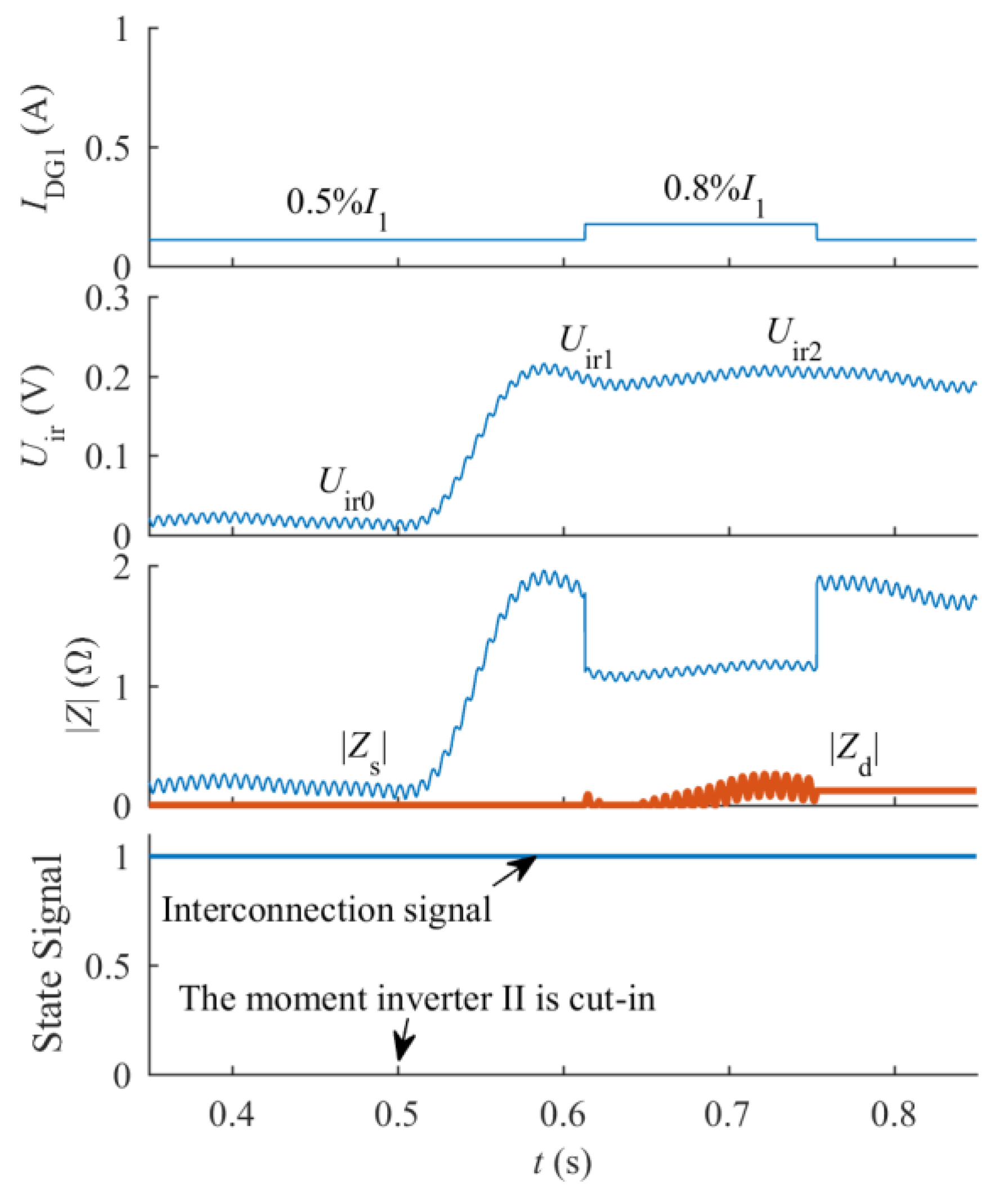
4.2. A Distributed Generation Unit Cut-In Event

The whole test is carried out under a grid-connected condition. Inverter II is cut-in at 0.5 s and outputs a 1.1 A negative sequence second harmonic current. The results related to inverter I are shown in Figure 9.
In Figure 9, compared with the initial |Zs|, |Zd| is at an approximate level all the time. Accordingly, the grid-connected state is successfully determined. Meanwhile, Figure 8 and Figure 9 show that there are static impedance surges in both the two cases above. Consequently, the existing irregular current injection methods may deem both the cases to be island events. Obviously, there is a misjudgment. The simulation results are in accordance with the analyses in Section 3 which verify that the proposed method performs well and is not affected by a DG unit cut-in event.

5. Experiment

The experimental system is similar to that in Figure 7, and the main parts are still two inverters, a R-L-C load and a real 380 V/50 Hz power grid. Inverter I is still the observed object and the generation power will also match the load power in an island condition. The test procedure is the same as that in the previous section. The relevant parameters are shown in Table 2. Additionally, PR regulators are still used for current control and signal extraction is still based on Figure 4, where 2nd order filters (LPFs) are used.

5.1. An Island Event

Inverter I initially outputs a 0.55 A negative sequence second harmonic current. The experimental results are shown in Figure 10a,c. To further check the actual second harmonic current and voltage, their waveforms are achieved through offline filtering (band pass) the measured current (Phase A) and voltage (Phase A to Phase B) by Matlab, as shown in Figure 10b,d.
In Figure 10a,b, the amplitudes of i2h and u2h and their changes are generally consistent with IDG1 and the converted Uir (i.e., 3 U ir ), although the rise time of Uir is longer due to the fact that the filters used in the experiment and in Matlab are different. Hence, both the islanding detection and the second harmonic current control are successful.

5.2. A Unit Cut-In Event

When inverter II is cut-in, it outputs a 5 A negative sequence second harmonic current. The experimental results are shown in Figure 11. In Figure 11a, the |Zd| is almost constant, by which the event is successfully identified as a DG unit cut-in event. Although the magnitude increase of Uir is less than that in Figure 10a, it may be still deemed to be evidence of an island event according to the existing irregular current injection methods, and this probability will be greater if the second harmonic current injected by the DG unit cut-in is greater.
Compared with the previous simulation results, the entire detection process lasts longer in the experiments, for the cut-off frequency of the low-pass filters (i.e., LPFs in Figure 4a) is smaller in the experiments. This may cause the proposed method to not coordinate with far-fast automatic reclosing, which may take place within 0.5 s and thereby require that an island must be detected in 0.5 s or even less [31]. From the simulation and experimental results, this requirement is satisfied in the simulations, but not in the experiments. Thus, in order to satisfy this requirement in practical applications, improved or new signal extraction schemes should be studied, even if this may bring more computational burden. However, from the present standards, the proposed method makes correct and timely (in 2 s) judgments in both conditions [30].

6. Conclusions

DG unit cut-in events may be misdiagnosed as island events by the existing irregular current injection islanding detection methods. In view of this problem, this paper proposes a new irregular current injection method mainly based on an improved impedance measurement scheme. Compared with the general impedance measurement scheme, the improved scheme introduces dynamic impedance, by which island events can be distinguished from DG unit cut-in events. Furthermore, the proposed method can assist some other equipment in islanding detection. Compared with existing methods of the same type, the proposed method possesses better reliability and a wider use, which will be valuable in practical applications.
According to the previous analyses, simulations and experiments, and with reference to relevant literature, a comparison of the mentioned island detection methods is given in Table 3 [32,33,34].

Author Contributions

All authors contributed their advice to the implementation of simulation and experiment. M.L. and W.Z. conceived the methodology; M.L. programmed the digital signal processor and implemented the validation; Q.W. did a writing-review & editing and gave advice on the structure of this paper.

Conflicts of Interest

The authors declare no conflict of interest.

References

  1. Voglitsis, D.; Papanikolaou, N.; Kyritsis, A.C. Incorporation of harmonic injection in an interleaved flyback inverter for the implementation of an active anti-islanding technique. IEEE Trans. Power Electron. 2017, 32, 8526–8543. [Google Scholar] [CrossRef]
  2. Emadi, A.; Afrakhte, H.; Sadeh, J. Fast active islanding detection method based on second harmonic drifting for inverter-based distributed generation. IET Gener. Transm. Dis. 2016, 10, 3470–3480. [Google Scholar] [CrossRef]
  3. Wu, Z.; Yang, F.; Luo, Z.; Hang, Q.L. A novel active islanding fault detection based on even harmonics injection and set-membership filtering. In Proceedings of the 11th World Congress on Intelligent Control and Automation, Shenyang, China, 29 June–4 July 2015; IEEE: Piscataway, NJ, USA, 2015; pp. 3683–3689. [Google Scholar]
  4. Timbus, A.V.; Teodorescu, R.; Blaabjerg, F.; Borup, U. Ens detection algorithm and its implementation for pv inverters. In Proceedings of the IEE Proceedings—Electric Power Applications, 20 March 2006; IET: Stevenage, UK, 2006; Volume 153. [Google Scholar] [CrossRef]
  5. Tedde, M.; Smedley, K. Anti-islanding for three-phase one-cycle control grid tied inverter. IEEE Trans. Power Electron. 2014, 29, 3330–3345. [Google Scholar] [CrossRef]
  6. Hou, C.-C.; Chen, Y.-C. Active anti-islanding detection based on pulse current injection for distributed generation systems. IET Power Electron. 2013, 6, 1658–1667. [Google Scholar] [CrossRef]
  7. Karimi, H.; Yazdani, A.; Iravani, R. Negative-sequence current injection for fast islanding detection of a distributed resource unit. IEEE Trans. Power Electron. 2008, 23, 298–307. [Google Scholar] [CrossRef]
  8. Kim, H.J.; Kim, D.H.; Han, B.M. Islanding detection method with negative-sequence current injection under unbalanced grid voltage. In Proceedings of the Future Energy Electronics Conference, Taipei, Taiwan, 1–4 November 2015. [Google Scholar] [CrossRef]
  9. Cai, W.; Liu, B.; Duan, S.; Zou, C. An islanding detection method based on dual-frequency harmonic current injection under grid impedance unbalanced condition. IEEE Trans. Ind. Inform. 2013, 9, 1178–1187. [Google Scholar] [CrossRef]
  10. Asiminoaei, L.; Teodorescu, R.; Blaabjerg, F.; Borup, U. A digital controlled pv-inverter with grid impedance estimation for ens detection. IEEE Trans. Power Electron. 2005, 20, 1480–1490. [Google Scholar] [CrossRef]
  11. Vijayakumari, A.; Devarajan, A.T.; Devarajan, N.; Vijith, K. Dynamic grid impedance calculation in d-q frame for micro-grids. In Proceedings of the Power and Energy Systems Conference: Towards Sustainable Energy, Bangalore, India, 13–15 March 2014; IEEE: Piscataway, NJ, USA, 2014. [Google Scholar] [CrossRef]
  12. Dai, Z.; Chong, Z.; Liu, X.; Li, C. Active islanding detection method based on grid-connected photovoltaic inverter and negative sequence current injection. In Proceedings of the International Conference on Power System Technology, Chengdu, China, 20–22 October 2014; IEEE: Piscataway, NJ, USA, 2014; pp. 1685–1690. [Google Scholar]
  13. Briz, F.; Diaz-Reigosa, D.; Blanco, C.; Guerrero, J.M. Coordinated operation of parallel-connected inverters for active islanding detection using high-frequency signal injection. IEEE Trans. Ind. Appl. 2014, 50, 3476–3484. [Google Scholar] [CrossRef]
  14. Reigosa, D.D.; Briz, F.; Charro, C.B.; Guerrero, J.M. Islanding detection in three-phase and single-phase systems using pulsating high-frequency signal injection. IEEE Trans. Power Electron. 2015, 30, 6672–6683. [Google Scholar] [CrossRef]
  15. Kim, B.H.; Sul, S.K.; Lim, C.H. Anti-islanding detection method using negative sequence voltage. In Proceedings of the Power Electronics and Motion Control Conference, Harbin, China, 2–5 June 2012; IEEE: Piscataway, NJ, USA, 2012; pp. 604–608. [Google Scholar]
  16. García, P.; Guerrero, J.M.; García, J.; Navarro-Rodríguez, Á.; Sumner, M. Low frequency signal injection for grid impedance estimation in three phase systems. In Proceedings of the Energy Conversion Congress and Exposition, Pittsburgh, PA, USA, 14–18 September 2014; IEEE: Piscataway, NJ, USA, 2014; pp. 1542–1549. [Google Scholar] [Green Version]
  17. Hu, S.H.; Tsai, H.T.; Lee, T.L. Islanding detection method based on second-order harmonic injection for voltage-controlled inverter. In Proceedings of the Future Energy Electronics Conference, Taipei, Taiwan, 1–4 November 2015; IEEE: Piscataway, NJ, USA, 2014. [Google Scholar] [CrossRef]
  18. Vahedi, H.; Karrari, M. Adaptive fuzzy sandia frequency-shift method for islanding protection of inverter-based distributed generation. IEEE Trans. Power Deliv. 2013, 28, 84–92. [Google Scholar] [CrossRef]
  19. Lin, F.-J.; Chiu, J.-H.; Chang, Y.-R.; Huang, Y.-S.; Tan, K.-H. Active islanding detection method using d-axis disturbance signal injection with intelligent control. IET Gener. Transm. Distrib. 2013, 7, 537–550. [Google Scholar] [CrossRef]
  20. Al Hosani, M.; Qu, Z.; Zeineldin, H.H. Scheduled perturbation to reduce nondetection zone for low gain sandia frequency shift method. IEEE Trans. Smart Grid 2015, 6, 3095–3103. [Google Scholar] [CrossRef]
  21. Al Hosani, M.; Qu, Z.; Zeineldin, H.H. A transient stiffness measure for islanding detection of multi-dg systems. IEEE Trans. Power Deliv. 2015, 30, 986–995. [Google Scholar] [CrossRef]
  22. Gupta, P.; Bhatia, R.S.; Jain, D.K. Average absolute frequency deviation value based active islanding detection technique. IEEE Trans. Smart Grid 2015, 6, 26–35. [Google Scholar] [CrossRef]
  23. Khodaparastan, M.; Vahedi, H.; Khazaeli, F.; Oraee, H. A novel hybrid islanding detection method for inverter-based dgs using sfs and rocof. IEEE Trans. Power Deliv. 2017, 32, 2162–2170. [Google Scholar] [CrossRef]
  24. Alshareef, S.; Talwar, S.; Morsi, W.G. A new approach based on wavelet design and machine learning for islanding detection of distributed generation. IEEE Trans. Smart Grid 2014, 5, 1575–1583. [Google Scholar] [CrossRef]
  25. Fazio, A.; Russo, M.; Valeri, S. A new protection system for islanding detection in lv distribution systems. Energies 2015, 8, 3775–3793. [Google Scholar] [CrossRef]
  26. Saleh, S.A.; Aljankawey, A.S.; Ozkop, E.; Meng, R. On the experimental performance of a coordinated antiislanding protection for systems with multiple dgus. IEEE Trans. Power Electron. 2017, 32, 1106–1123. [Google Scholar] [CrossRef]
  27. Liu, X.; Kennedy, J.M.; Laverty, D.M.; Morrow, D.J.; McLoone, S. Wide-area phase-angle measurements for islanding detection—An adaptive nonlinear approach. IEEE Trans. Power Deliv. 2016, 31, 1901–1911. [Google Scholar] [CrossRef]
  28. Anne, R.; Katha Basha, F.; Palaniappan, R.; Oliver, K.L.; Thompson, M.J. Reliable generator islanding detection for industrial power consumers with on-site generation. IEEE Trans. Ind. Appl. 2016, 52, 668–676. [Google Scholar] [CrossRef]
  29. Llonch-Masachs, M.; Heredero-Peris, D.; Montesinos-Miracle, D. An anti-islanding method for voltage controlled vsi. In Proceedings of the European Conference on Power Electronics and Applications, Geneva, Switzerland, 8–10 September 2015; IEEE: Piscataway, NJ, USA, 2015. [Google Scholar] [CrossRef]
  30. IEE Standard Association. IEEE Standard for Interconnecting Distributed Resources with Electric Power Systems; IEEE: Piscataway, NJ, USA, 2003; pp. 1547–2003. [Google Scholar]
  31. Edwards, A.; Heerden, R.V.; Chowdhury, S.; Chowdury, S.P.; Kang, H. Fast auto-reclose function for 765 kv lines in the proximity of resonant line voltages. In Proceedings of the IET International Conference on Developments in Power System Protection, Manchester, UK, 29 March–1 April 2010; IEEE: Piscataway, NJ, USA, 2010. [Google Scholar] [CrossRef]
  32. Mahat, P.; Chen, Z.; Bak-Jensen, B. Review of islanding detection methods for distributed generation. In Proceedings of the International Conference on Electric Utility Deregulation and Restructuring and Power Technologies, Nanjing, China, 6–9 April 2008; IEEE: Piscataway, NJ, USA, 2008; pp. 2743–2748. [Google Scholar]
  33. Teodorescu, R.; Liserre, M.; Rodríguez, P. Grid Converters for Photovoltaic and Wind Power Systems; John Wiley & Sons: Hoboken, NJ, USA, 2011; pp. 93–122. [Google Scholar]
  34. Miller, L.E.; Schoene, J.; Kunte, R.; Morris, G.Y. Smart grid opportunities in islanding detection. In Proceedings of the 2013 IEEE Power and Energy Society General Meeting (PES), Vancouver, BC, Canada, 21–25 July 2013; IEEE: Piscataway, NJ, USA, 2013. [Google Scholar] [CrossRef]
Figure 1. Inverter-based distributed generation (DG).
Energies 11 02474 g001
Figure 2. Irregular currents and irregular voltages.
Energies 11 02474 g002
Figure 3. Changes of Uir in the improved impedance measurement scheme.
Energies 11 02474 g003
Figure 4. Negative sequence second harmonic voltages signal extraction. (a) Signal flow; (b) ABC to dq(−2ω) reference frame transformation.
Energies 11 02474 g004
Figure 5. Flow chart of the proposed islanding detection method.
Energies 11 02474 g005
Figure 6. Non-detection zone (NDZ) of the proposed method.
Energies 11 02474 g006
Figure 7. Three-phase simulation platform.
Energies 11 02474 g007
Figure 8. Island event occurring. (a) Continuously measuring |Zd| after the command of increasing IDG1 is issued; (b) Measuring |Zd| until Uir is stable at Uir2.
Energies 11 02474 g008
Figure 9. DG unit cut-in event occurring.
Energies 11 02474 g009
Figure 10. Island event occurring and the related waveforms of current and voltage. (a) The whole process of the islanding detection; (b) Waveforms of the second harmonic current and voltage during the islanding detection; (c) Measured current and voltage before and after the change of IDG1; (d) Waveforms of the second harmonic current and voltage contained in the measured current and voltage shown in (c). CH7: the measured current; CH8: the measured phase-to-phase voltage; i2h: the second harmonic current; u2h: the second harmonic voltage. Theoretically, the amplitude of u2h (phase-to-phase voltage) is 3 times the Uir (phase-to-ground voltage) in (a).
Energies 11 02474 g010
Figure 11. DG unit cut-in event occurring and the related waveforms of current and voltage. (a) The whole process before and after the event; (b) Waveforms of the second harmonic current and voltage during the whole process; (c) Measured current and voltage before and after the change of IDG1; (d) Waveforms of the second harmonic current and voltage contained in the measured current and voltage shown in (c).
Energies 11 02474 g011
Table 1. Parameters used in the simulation.
R (Ω)L (mH)C (mF)Rg (Ω)Lg (mH)k1k2Tlim (s)udc (V)fPWM (kHz)Lf (mH)
14.5218.490.54810.090.3221695105
Table 2. Parameters used in the experiment.
R (Ω)L (mH)C (mF)k1k2Tlim (s)
51.268.40.163221
Table 3. Comparison of the mentioned island detection methods: non-detection zone (NDZ); total harmonic distortion (THD).
MethodsDetection speedNDZEffect on power qualityCost
Active methodsExisting irregular current injection methodsMediumSmallMedium (THD)Low
The proposed methodLowSmallMedium (THD)Low
Frequency shift methodsMediumSmallLow (reactive power disturbance)Low
Passive methodsHighLargeNoneLow
Remote methodsVery highNoneNearly noneHigh

