Article

Comparative Analysis of Bearing Current in Wind Turbine Generators

1
School of Electrical Engineering, Beijing Jiaotong University, Haidian District, Beijing 100044, China
2
Department of Electrical Engineering, The Hong Kong Polytechnic University, Hong Kong, China
*
Author to whom correspondence should be addressed.
Energies 2018, 11(5), 1305; https://doi.org/10.3390/en11051305
Submission received: 3 April 2018 / Revised: 16 May 2018 / Accepted: 16 May 2018 / Published: 20 May 2018
(This article belongs to the Special Issue Modeling of Wind Turbines and Wind Farms)

Abstract

:
Bearing current problems frequently appear in wind turbine systems, which cause wind turbines the break down and result in very large losses. This paper investigates and compares bearing current problems in three kinds of wind turbine generators, namely doubly-fed induction generator (DFIG), direct-drive permanent magnet synchronous generator (PMSG), and semi-direct-drive PMSG turbines. Common mode voltage (CMV) of converters is introduced firstly. Then stray capacitances of three kinds of generators are calculated and compared through the finite element method. The bearing current equivalent circuits are proposed and simulations of the bearing current are carried out. It is verified that the bearing currents of DFIGs are more serious than the two kinds of PMSG, while common mode current (CMC) of the direct-drive PMSG is much greater than the other two types of wind turbine generators.

1. Introduction

Wind power has become the fastest growing clean energy due to its advantages of being clean, their short construction period, and low operation cost [1,2] among all the renewable energy power generation technologies. At present, megawatt-scale technology has good prospects in wind turbine applications. Doubly fed induction generators (DFIGs) and permanent magnet synchronous generators (PMSGs) are the most widely used in wind power generation. DFIGs adopt rotor converter power supplies, in which the converter only needs 30% of the rated power and the whole cost of the system is greatly reduced. PMSGs require a full power converter, but with no-excitation winding, the operating efficiency is higher. PMSGs can be classified into direct-drive generators and semi-direct-drive generators. Since there is no gearbox in direct-drive PMSGs, the cost for drive parts is saved. PMSGs have low rated speed, multiple poles, and permanent magnets that are usually mounted on the rotor surface. Semi-direct-drive PMSGs need an acceleration gear box. With higher speed and fewer poles, a built-in permanent magnetic structure is usually used in semi-direct-drive PMSGs. Additionally, the size of semi-direct-drive PMSGs is smaller and the installation and transportation of direct-drive PMSGs are more convenient than direct-drive PMSGs.
Whether it is a DFIG or PMSG, the generator power supply current always goes through the converter to the power grid. The switching device of the converter will produce a high-frequency common-mode voltage, which couples with the generator stray capacitance and induces a bearing voltage between the outer raceway and inner raceway of the bearing. If the bearing voltage exceeds the threshold voltage of the bearing lubricating oil film, which is located between the bearing ball and the raceway, the oil film will break down. This would result in the discharge of the bearing current and lead to bearing premature failure. Kevin Alewine, an expert at Shermco Industry in the United States, counted failure types of approximately 1200 wind turbines maintained by the company between 2005 and 2010. The failure rate of the bearings with power from 1 MW to 2 MW is 70% [1], as shown in Figure 1. No matters on land or sea, wind turbines are installed on tall towers, and the maintenance and overhauling caused by bearing failures are complicated and expensive. Therefore, it is of great value to investigate the mechanism of bearing current and investigate mitigation methods.
Aiming to solve the problem of bearing current in a variable frequency AC motor, Chen and Busse [3,4,5] pointed out that the high frequency common-mode voltage of the inverter and the stray capacitances of motors are the critical reasons of the bearing currents. Muetze [6,7,8,9] focused on analyzing the characteristics of Electric discharge machining (EDM) current and circulating bearing current, and put forward the relevant suppression methods [10,11,12,13]. With the development of wind power generation technologies, the bearing current problems on wind generators appear. According to [1], the proportion of the bearing electric erosion of the wind turbines is higher than that of the industrial motors, as shown in Figure 2. Zitzelsberger established the DFIG bearing current analysis model [14]. Adabi et al. studied the stray capacitance parameters of the bearing current model, and gave the relevant analytical formulas. At the same time, they analyzed the machine design’s influence on the stray capacitance factors [15,16]. The bearing current problem of DFIGs received a significant amount of attention. However, bearing current problems existing in PMSG systems caused by using converters still have not been clearly investigated before.
In this paper, the bearing currents of DFIGs, direct-drive PMSGs, and semi-direct-drive PMSGs are studied and compared. Firstly, the common mode voltage of converter is introduced. Then the calculation method on the stray capacitances of three kinds of generators is put forward and the bearing current equivalent models are built. Finally, the simulation of the converter-wind turbine generator system is carried out and a comparative study of bearing currents of three kinds of generators is carried out.

2. Common Mode Voltage Generation

A two-level voltage converter is often applied to achieve DC/AC conversion in wind generation systems, as shown in Figure 3, where Ud is the DC link voltage. Switches VT1–VT6 are turned on/off by Pulse Width Modulation (PMW) waves, and the Digital Signal Processing (DSP) microcontroller are used to realize the SPWM strategy.
In Figure 3, the voltage equations are:
{ U a = R i a + L d i a d t + U Ng U b = R i b + L d i b d t + U Ng U c = R i c + L d i c d t + U Ng
where Ua, Ub, and Uc are the output three-phase voltage; UNg is the voltage between the midpoint of the three-phase stator winding and the ground; ia, ib, and ic are the output currents flowing through the generator winding; R and L are the winding resistance and leakage inductance of each phase of the generator.
From Equation (1), the following equations can be derived:
U a + U b + U c = R ( i a + i b + i c ) + L d ( i a + i b + i c ) d t + 3 U Ng
U Ng = V com
where Vcom is the common-mode voltage, which is the same as UNg.
In wind turbines, if the stator three-phase windings are perfectly symmetrical, the sum of ia, ib, and ic is approximately 0, and Equation (2) is rewritten as,
V com = U a + U b + U c 3
In the system power of a symmetrical three-phase sinusoidal alternating current, the sum of the three-phase AC voltage is zero, which means the common-mode voltage is zero. However, in the inverter power system with SPWM control, the sum of the three-phase voltage is not zero. In order to prevent bridge run-through, the up and down switches of the same legs cannot be turned on at the same time. If ‘1’ indicates the up-side switching on, and ‘0’ indicates the down-side switching on, there are eight switch state combinations in total. If the mid-point of the two electrolytic capacitors in the converter DC link are taken as the system reference point, the common mode voltage and the state of the switch can be expressed in Table 1 or given by Equation (5),
V com = { ± U d 2 s t a t e s   S 0 , S 7 ± U d 6 o t h e r   s t a t e s
The common-mode voltage waveform of two-level inverters is shown in Figure 4, which is a staircase wave, and consists of two levels, ±Ud/6 and ± Ud/2.

3. Bearing Current Analysis of Doubly-Fed Induction Generator (DFIG)

In DFIGs, the common mode voltage of the converter is applied to the rotor winding. The stray capacitances of the generator constitute the coupling paths of the common mode voltage to the bearing. In order to analyze the bearing currents of DFIG, the stray capacitances of the generator should be acquired. The calculation accuracy of the capacitances would affect the prediction accuracy of bearing currents.

3.1. Stray Capacitances of Doubly-Fed Induction Generator (DFIG)

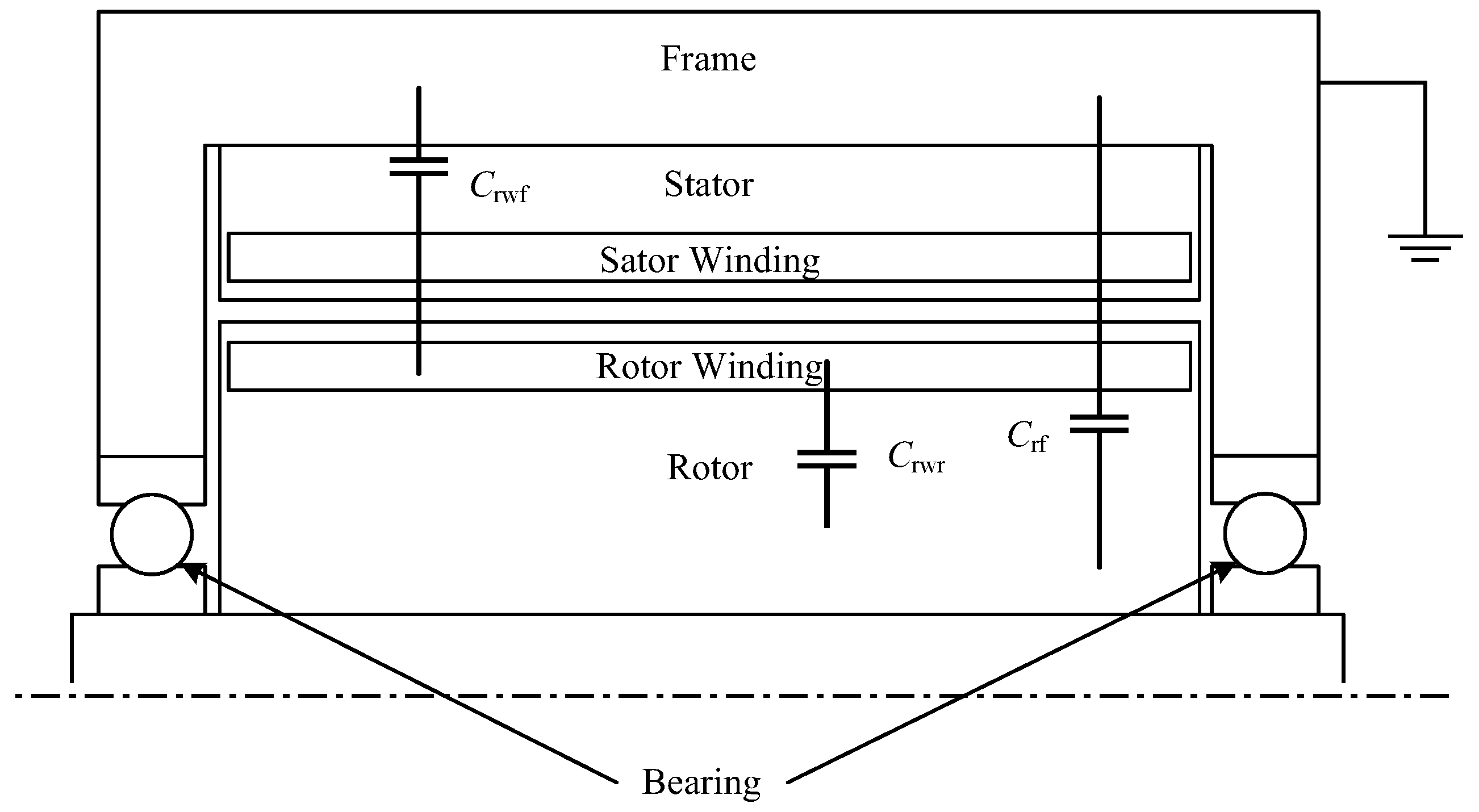
In DFIGs, there are four parts of the conductor, namely, the stator winding, rotor winding, rotor core, and stator core. The stator core connects to the frame and the rotor core connects to the shaft. Then, the stator core and frame are at the same electric potential, and the rotor core and shaft are also at the same potential. According to the partial capacitance theory of multi-conductor systems, the dielectric materials between the two conductors can induce stray capacitance. Therefore, there are three stray capacitances—Crwf, Crwr, and Crf—in DFIGs, where Crwf is the capacitance between the rotor winding and the frame, Crwr is the capacitance between the rotor winding and the rotor core, and Crf is the capacitance between the rotor core and the frame. The stator winding has no influence on other parts. The specific capacitance distribution in the DFIG is shown in Figure 5.
Due to the complex structure of the generator, it is not easy to obtain an accurate result from the analytical method, as in [17]. Since the materials and the shapes of different parts are not as simple as the plate capacitor, the assumption used in the analytical method would cause errors. In order to obtain the accurate stray capacitances of the DFIG, the electromagnetic field numerical calculation based on the finite element method (FEM) is adopted in this paper.
Ignoring the generator end effect, a 2D model can be built in ANSYS Maxwell (Version, 16.0,ANSYS, Pittsburgh, PA, USA) based on the generator structure parameters. The electrostatic field solver is adopted. The boundary problem of electric potential φ satisfies following Poisson equation, where x, y are coordinates in space:
2 φ x 2 + 2 φ y 2 = 0
The stator core is taken as the reference; the rotor winding and rotor core are taken as independent conductors applying different voltages. We set the matrix parameter solving item, then set the proper mesh subdivision of the solution domain and perform the numerical calculation. The electrostatic induction coefficient matrix [β] can be obtained, which contains following elements:
[ β ] = [ β rw β rw _ r β r _ wr β r ]
where the subscript rw indicates the rotor winding and r indicates the rotor core. βrw is the induction coefficient between rotor winding and reference conductor, βr is the induction coefficient between the rotor and reference conductor, βrw_r is the induction coefficient between the rotor winding and rotor. According to the theory of the partial capacitance of multi-conductors, the stray capacitances in the DFIG can be deduced from coefficients of electrostatic induction:
{ C rwf = β rw + β rw _ r C rwr = β rw _ r C rf = β r + β r _ rw
To acquire the actual results, the above values should multiply the generator’s effective axial length.
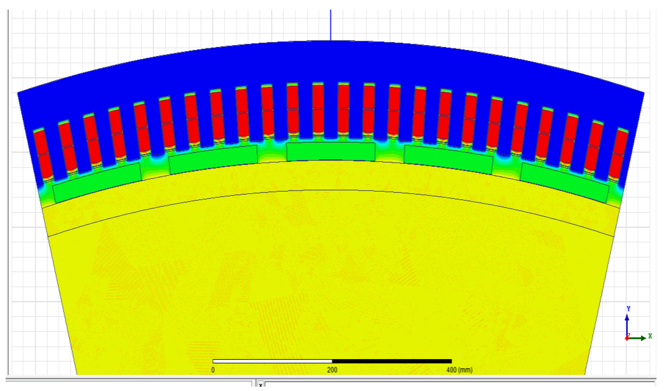
The stray capacitances of a 1.5 MW DFIG are calculated through the above method. The generator model is shown in Figure 6, where the insulation material in the generator is accurately described. The parameter of the DFIG is shown in Table 2.
With the finite element numerical calculation, the stray capacitances of the DFIG are obtained as shown in Table 3.
Among three capacitances, Crwr is much greater than the two other capacitances. This is because Crwr is the capacitance between the rotor core and rotor windings. Comparing the two other capacitances, the insulation distance is shorter, the conductor surface is greater, and the permittivity is larger. All of these factors cause Crwr to be much greater than the two others. Crwr is a critical capacitance in the bearing current problem of DFIGs.

3.2. Bearing Current Model of the DFIG

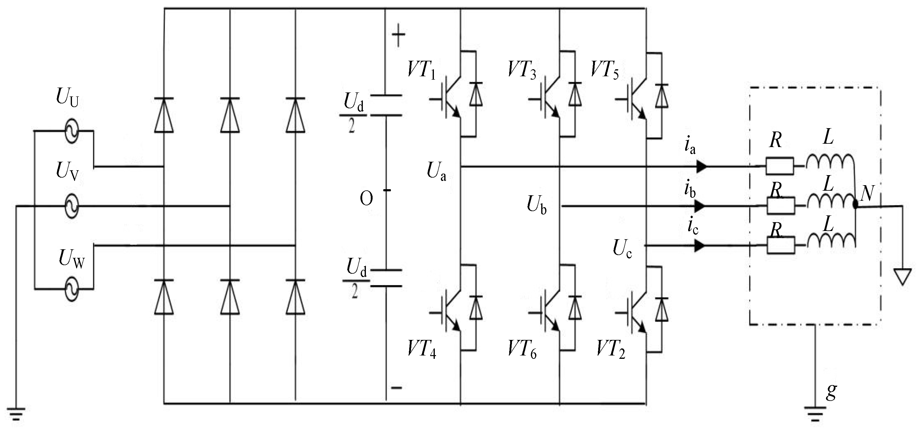
The rotor windings of the DFIG are connected to the converter. The common mode voltage of the converter exists at the neutral point of the rotor windings and the ground. Coupled by the generator stray capacitances, common mode voltage induces the voltage on the rotor shaft. Common mode current will return to the convertor. Assuming the frame of the generator is well grounded, the equivalent common mode circuit of the DFIG is shown in Figure 7.
In Figure 7, Vcom is the common-mode voltage of the converter; RW denotes rotor windings; R denotes the rotor core; and F denotes the frame. The bearing inner raceway connects the shaft, namely, the bearing inner raceway is at the same potential as the rotor core. The bearing outer raceway connects the stator end cover, namely, the outer raceway is at the same potential as the stator core and frame. Balls of the bearing separate the inner raceway and outer raceway; lubricating grease exists on the balls and raceways. When the bearing oil film has integrity, the bearing can be taken as a capacitance.
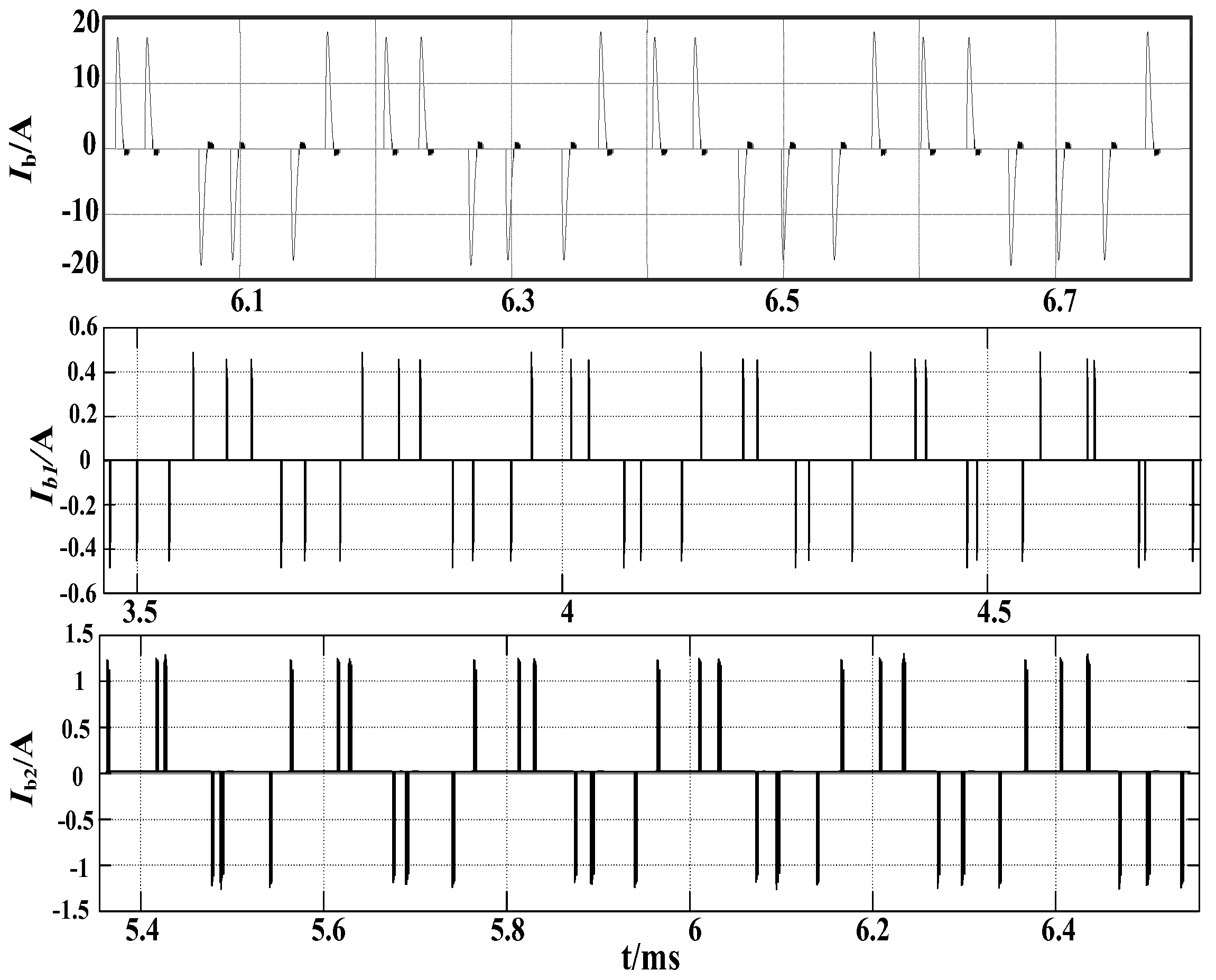
 Cb1 and Cb2 in Figure 7 denote the equivalent capacitance of the drive end and non-driven end bearing, respectively.
Supposing the generator stator frame is well grounded, the high-frequency Vcom acts on the generator rotor winding. Coupled with stray capacitances, inductive voltage Vb would appear between the rotor and frame. Vb acts simultaneously between the inner and outer bearing raceways. When the electric filed intensity of the oil surpasses the breakdown intensity, it will lead to the oil film breaking down and produce a discharge current.
The bearing voltage ratio (BVR) can be defined as the ratio of the bearing voltage Vb to the rotor winding common-mode voltage Vcom, which is an indicator of bearing damage. The BVR of the DFIG is shown in Equation (9):
BVR = V b V com = C r wr C rwr + C rf + C b 1 + C b 2
The bearing capacitance is much smaller than capacitances Crwr and Crf, and it usually changes with the temperature, speed, and load. If the influence of Cb on the BVR is small, then Cb1 and Cb2 can be treated as Cb1 = Cb2 = 0. Using the capacitance in Table 2, the bearing voltage ratio of this DFIG is 97.9%, which is much greater than the BVR of induction motors supplied by a PWM inverter, which is usually less than 10% [6]. The significant difference of the BVR between the two kinds of machines is because the common mode voltage comes from different sides of the electrical machine. In the DFIG, the rotor winding is connected to the converter, and in induction motors powered by an inverter, the stator winding is connected to the inverter. In the latter condition coupling is on the capacitance of the stator winding to the rotor, which is very small because the two parts are separated by an airgap. Such a high BVR of the DFIG indicates that the bearing voltage of the DFIG is dangerous and harmful to the bearings.

4. Bearing Current Analysis of Permanent Magnet Synchronous Wind Turbine

Permanent magnet synchronous wind generation systems can be divided into direct-drive and semi-direct-drive types. Direct-drive PMSGs have multiple poles and large diameters, in which the permanent magnets are usually surface mounted installations, as shown in Figure 8a. The permanent magnet in the inner rotor PMSG is directly adhered to the outer surface of the rotor core by a specific adhesive. Semi-direct-drive PMSGs are high-speed and with fewer poles. Permanent magnets are usually built-in installations, as shown in Figure 8b. The permanent magnets are placed in pre-opened slots in the designated area of the rotor core.

4.1. Stray Capacitances of Permanent Magnet Synchronous Generators (PMSGs)

There are four conductor parts in the direct-drive PMSG, which are, respectively, the stator winding, stator core, rotor core, and permanent magnet. The stator windings and the stator core are isolated by the insulating layer. The stator core and the rotor core are separated by air gap. The stator core and the frame are electrically connected. The rotor core and the rotor shaft are connected. The rotor core and the permanent magnet can be regarded as the same potential conductors. Hence, there are three stray capacitances in the generator. Respectively, Cwf is the capacitance between the stator windings and the stator, Cwr is the capacitance between the stator windings and the rotor and Crf is the capacitance between the rotor core and stator core.
Similar to the direct-drive PMSG, the same four conductor parts also exist in the semi-direct-drive PMSG, which uses a built-in permanent magnet rotor. The rotor core and the permanent magnet can be treated as the same potential conductors, and three stray capacitances Cwf, Cwr, and Crf exist in the semi-direct-drive PMSGs.
The stray capacitances of one 2 MW direct-drive and one 2 MW semi-direct-drive PMSG are calculated through the electromagnetic field numerical method, respectively. The generator models are shown in Figure 9 and Figure 10. The parameters of the two PMSGs are shown in Table 4.
Stray capacitance calculation results of the two generators are shown in Table 5.
The difference between these two kinds of generators can be seen from Table 5. The capacitances of the direct-drive PMSG are greater than those of semi-direct-drive PMSG. Cwf in the direct-drive PMSG is about nine times of that in the semi-direct-drive PMSG, which is because the slot number of the direct-drive PMSG is much greater than the semi-direct-drive PMSG. Capacitance Cwf is proportional to the slot number.

4.2. Bearing Current Model of PMSG

When common-mode voltage of converter exists between stator winding neutral point and ground, the bearing current equivalent model of the PMSG can be obtained, as shown in Figure 11. Both direct-drive and semi-direct-drive PMSGs can adopt this model.
According Figure 11, the BVR of permanent magnet synchronous wind generator is:
BVR = V b V com = C wr C wr + C rf + C b 1 + C b 2
Using the capacitance results in Table 4 and neglecting the bearing capacitance, BVR of the direct-drive PMSG and semi-direct-drive PMSG can be acquired. The BVR comparison of three kinds of wind turbine generators is shown in Table 6.
BVRs of two PMSGs are less than 20%, which is much smaller than DFIG. This is because the converter connects to stator windings of PMSGs, and the coupling between the stator and rotor is very weak. Then, the bearing voltage induced by common mode voltage of the converter is lower than that in DFIGs. However, the BVR of the PMSG is greater than that of the induction motor powered by an inverter, which is because the power level and the size of the PMSG is greater than ordinary induction motors. From Table 5 we can see the bearing failure rate of PMSGs will be lower than the DFIG, which is one of the reasons for the wide application of PMSGs in wind power generation systems.

5. Bearing Current Simulations of Wind Turbine Generators

Taking the DFIG system as an example, the converter output is combined with the stray capacitance network of the DFIG to obtain the bearing current simulation model. The structure is shown in Figure 12.
In Figure 12, the converter is connected to the rotor winding of the DFIG, and a high-frequency common-mode voltage Vcom exists between the rotor windings and the ground to form a common mode loop through the stray capacitance of the generator. Common mode current Icom flows from the stator frame to ground. Ud is the DC bus voltage; resistance and leakage inductance of each phase of the stator windings are represented by R and L. Assuming that the generator frame is well grounded, the ground impedance is ignored. When large breakdown currents flow through the bearing, the bearing is equivalent to a resistance [18]. Equivalent switches k1 and k2 are used to simulate the breakdown process of the oil film. Before the oil film breaks down, switch k1 closes and k2 opens; the bearing acts as the equivalent of a capacitor. After the film breaks down, the switch k1 opens and k2 closes, the bearing acts as the equivalent of a breakdown resistance Rb.
The simulation model is setup with MATLAB/Simulink (R2014a, Mathworks, Natic, MA, USA. The capacitances of the 1.5 MW DFIG in Table 3 are adopted. Assuming Cb1 = Cb2 = 120 pF, and the bearing equivalent resistance Rb = 10 Ω, the threshold voltage of the bearing equivalent capacitor breakdown is ±15 V. The direct current bus voltage Ud is 1100 V, and the carrier frequency f is 5 kHz. The common mode current Icom and the bearing current Ib are calculated.
The same simulations are applied to the direct-drive and semi-direct-drive PMSGs. The bearing current (electric discharge machining current) simulation results of the three kinds of generators are shown in Figure 13.
The comparison of the peak values of common-mode current and bearing current of the three kinds of generator is shown in Table 7.
Table 7 shows that direct-drive and semi direct-drive PMSG bearing currents are much smaller than in the DFIG. However, the common mode current of the direct-drive DMSG is much larger than the DFIG and semi-direct-drive PMSG, which is because the stray capacitance of the PMSG winding and frame is much larger than in the DFIG.
Common mode current through the stray capacitance formed eddy currents in the stator core, which caused generator thermal loss. At the same time, the current flowing through the ground wire into the grid will cause harmonic interference in power grid. Bearing current generated by the breakdown of the bearing will cause the metal to melt near the breakdown point and generate pit points, which leads to premature failure of the bearing. Therefore, it is necessary to take effective measures to suppress common-mode current and bearing current.
The measurement of bearing currents in megawatt wind turbines has not been conducted anywhere in the world. Since the bearing currents cannot be directly measured, the test is a difficult task. This will be our future research content.

6. Conclusions

In this paper, three kinds of widely used wind generators—DFIG, direct-drive PMSG, and semi-direct-drive PMSG—are compared on the bearing current characteristics. The simulation results reveal that the bearing current of DFIG is much larger than the PMSGs. From the perspective of bearing reliability, PMSGs have more advantages than DFIG. From the common mode current point of view, the common-mode current of direct-drive PMSG is much larger than the semi-direct-drive PMSG and DFIG. Bearing current suppression methods for DFIG and common-mode current suppression methods for direct-drive PMSG should be further explored.

Author Contributions

Conceptualization, R.L.; Methodology, R.L.; Software, X.M., X.R.; Formal Analysis, X.M., X.R.; Resources, J.C.; Writing-Original Draft Preparation, X.M., X.R.; Writing-Review & Editing, R.L., S.N. Funding Acquisition, R.L., J.C.

Funding

This research was funded by the National Natural Science Foundation of China grant number [51777008, 51577007].

Acknowledgments

The authors express their gratitude to the National Natural Science Foundation of China.

Conflicts of Interest

The authors declare no conflict of interest.

References

  1. Alewine, K.; Chen, W. A review of electrical winding failures in wind turbine generators. IEEE Trans. Electr. Insul. Mag. 2012, 28, 8–13. [Google Scholar] [CrossRef]
  2. Hoppler, R.; Errath, R.A. Motor Bearings, not just a piece of metal. In Proceedings of the IEEE-IAS/PCA Cement Industry Conference, Charleston, SC, USA, 29 April–3 May 2007. [Google Scholar]
  3. Chen, S.; Lipo, T.; Fitzgerald, D. Source of induction motor bearing currents caused by PWM inverters. IEEE Trans. Energy Convers. 1996, 11, 25–32. [Google Scholar] [CrossRef]
  4. Busse, D.; Erdman, J.; Kerkman, R.; Schlegel, D.; Skibinski, G. System electrical parameters and their influence effect on bearing currents. IEEE Trans. Ind. Appl. 1997, 33, 577–584. [Google Scholar] [CrossRef]
  5. Busse, D.; Erdman, J.; Kerkman, R.; Schlegel, D.; Skibinski, G. Bearing Currents and Their Relationship to PWM Drives. IEEE Trans. Power Electron. 1997, 12, 243–252. [Google Scholar] [CrossRef]
  6. Muetze, A. Bearing Currents in Inverter-Fed AC-Motors. Ph.D. thesis, Darmstadt Univ. of Technology, Shaker Verlag, Aachen, Germany, 2004. [Google Scholar]
  7. Binder, A.; Muetze, A. Scaling Effects of Inverter-Induced Bearing Currents in AC Machines. IEEE Trans. Ind. Appl. 2007, 2, 769–776. [Google Scholar]
  8. Muetze, A.; Tamminen, J.; Ahola, J. Influence of Motor Operating Parameters on Discharge Bearing Current Activity. IEEE Trans. Ind. Appl. 2011, 47, 1767–1777. [Google Scholar] [CrossRef]
  9. Muetze, A.; Binder, A. Techniques for Measurement of Parameters Related to Inverter-Induced Bearing Currents. IEEE Trans. Ind. Appl. 2007, 43, 1274–1283. [Google Scholar] [CrossRef]
  10. Muetze, A. Scaling Issues for Common-Mode Chokes to Mitigate Ground Currents in Inverter-Based Drive Systems. IEEE Trans. Ind. Appl. 2009, 45, 286–294. [Google Scholar] [CrossRef]
  11. Charles, R.; Muetze, A. Simulation Model of Common-Mode Chokes for High-Power Applications. IEEE Trans. Ind. Appl. 2010, 46, 884–891. [Google Scholar]
  12. Muetze, A.; Charles, R. Simplified Design of Common-Mode Chokes for Reduction of Motor Ground Currents in Inverter Drives. IEEE Trans. Ind. Appl. 2011, 47, 2570–2577. [Google Scholar] [CrossRef]
  13. Muetze, A.; Binder, A. Calculation of motor capacitances for prediction of the voltage across the bearings in machines of inverter-based drive systems. IEEE Trans. Ind. Appl. 2007, 43, 665–672. [Google Scholar] [CrossRef]
  14. Zitzelsberger, J.; Hofmann, W.; Wiese, A.; Stupin, P. Bearing currents in doubly-fed induction generators. In Proceedings of the Power Electronics and Applications Conference, Dresden, Germany, 11–14 Septemper 2005. [Google Scholar]
  15. Adabi, J.; Zare, F.; Ghosh, A.; Lorenz, R.D. Calculations of capacitive couplings in induction generators to analyse shaft voltage. IET Power Electron. 2010, 3, 379–390. [Google Scholar] [CrossRef] [Green Version]
  16. Adabi, M.E.; Vahed, A. A survey of shaft voltage reduction strategies for induction generators in wind energy applications. Renewable Energy 2013, 50, 177–187. [Google Scholar] [CrossRef]
  17. Whittle, M.; Trevelyan, J.; Tavner, P.J. Bearing currents in wind turbine generators. J. Renew. Sustain. Energy 2013, 5, 053128. [Google Scholar] [CrossRef]
  18. Niskanen, V.; Muetze, A.; Ahola, J. Study on bearing impedance properties at several hundred kilohertz for different electric machine operating parameters. IEEE Trans. Ind. Appl. 2014, 5, 3438–3447. [Google Scholar] [CrossRef]
Figure 1. Failure types and occurrences proportion for generators of 1 to 2 MW [1].
Energies 11 01305 g001
Figure 2. Comparison of wind turbine failures with industrial machine failures. Distribution (%) of the failure types [1].
Energies 11 01305 g002
Figure 3. The converter–generator system.
Energies 11 01305 g003
Figure 4. Common mode voltage generated in the converter.
Energies 11 01305 g004
Figure 5. Stray capacitances of the doubly-fed induction generator (DFIG).
Energies 11 01305 g005
Figure 6. 2D model of a 1.5 MW DFIG.
Energies 11 01305 g006
Figure 7. Bearing current model of the DFIG.
Energies 11 01305 g007
Figure 8. Permanent magnet installation in a direct-drive permanent magnet synchronous generator (PMSG) (a) and semi-direct-drive PMSG (b).
Energies 11 01305 g008
Figure 9. Two megawatt direct-drive permanent magnet synchronous generator (PMSG) model.
Energies 11 01305 g009
Figure 10. Two megawatt semi-direct-drive PMSG model.
Energies 11 01305 g010
Figure 11. Bearing current equivalent model of the PMSG.
Energies 11 01305 g011
Figure 12. Analysis model of converter—DFIG system.
Energies 11 01305 g012
Figure 13. Bearing currents of DFIG, direct-drive PMSG, and semi-direct-drive PMSG from top to bottom.
Energies 11 01305 g013
Table 1. Common mode voltages under different switching states.
S0S1S2S3S4S5S6S7
switching state000001011010110100101111
Vcom U d 2 U d 6 U d 6 U d 6 U d 6 U d 6 U d 6 U d 2
Table 2. The 1.5 MW doubly-fed induction generator (DFIG) main parameters.
ParametersSymbolValue
Stator slot numberNs72
Rotor slot numberNr84
Length of iron coreL/mm652
Air gapδ/mm2.5
Stator inner radiusRs/mm285
Rotor slot wedge thicknessdr2/mm4.5
Stator slot wedge thicknessds1/mm4.5
Rotor slot insulation thicknessdrw1/mm1.35
Stator slot insulation thicknessdsw1/mm0.45
Rotor slot widthbr1/mm3
Stator slot widthbs1/mm15.2
Relative permittivity of slot wedgeεr13
Relative permittivity of slot insulationεr23.4
Table 3. Stray capacitances of a 1.5 MW DFIG.
Capacitance/nFCrwfCrwrCrf
DFIG0.027152.33.3
Table 4. Parameters of the 2 MW direct-drive permanent magnet synchronous generator (PMSG) and 2 MW semi-direct-drive PMSG.
ParametersSymbolDirect-Drive PMSGSemi Direct-Drive PMSG
Rated voltageUN/V660690
Rated frequencyfN/Hz8.570
Stator slot numberNs28872
Number of pole pairsP303
Permanent magnet widthWm/mm148.4126
Permanent magnet thicknesshm/mm2428
Iron core lengthLs/mm1500680
Air gapδ/mm66
Rotor outside radiusRr/mm1890306
Stator slot insulation thicknessdsw1/mm0.50.5
Stator slot wedge thicknessds2/mm22
Stator slot widthbs/mm1814
Relative permittivity of slot wedgeεr133
Relative permittivity of slot insulationεr23.43.4
Table 5. PMSG stray capacitance calculation results.
Capacitance/nFCwfCwrCrf
Direct-drive PMSG1607.43.3216.39
Semi Direct-drive PMSG182.40.341.42
Table 6. BVR comparison of three kinds of wind turbine generators.
DFIGDirect-Drive PMSGSemi Direct-Drive PMSG
BVR97.9%16.8%19.3%
Table 7. Comparison of common mode current and bearing current in three kinds of wind generators.
Wind TurbineIcom/AIb/A
DFIG2020
Direct-drive PMSG1501.3
Semi-direct-drive PMSG600.5

