Influences of Fracturing Fluid Injection on Mechanical Integrity of Cement Sheath under Four Failure Modes


Abstract
:1. Introduction
2. Mechanical Model Development and Solution
2.1. Basic Assumptions
- (1)
- The casing, cement sheath, and formation are continuous, homogeneous, and isotropic.
- (2)
- The casing-cement sheath-formation system is completely cemented and axisymmetric.
- (3)
- Both casing-cement sheath and cement sheath-formation interface satisfy the continuity conditions for radial stress and radial displacement.
- (4)
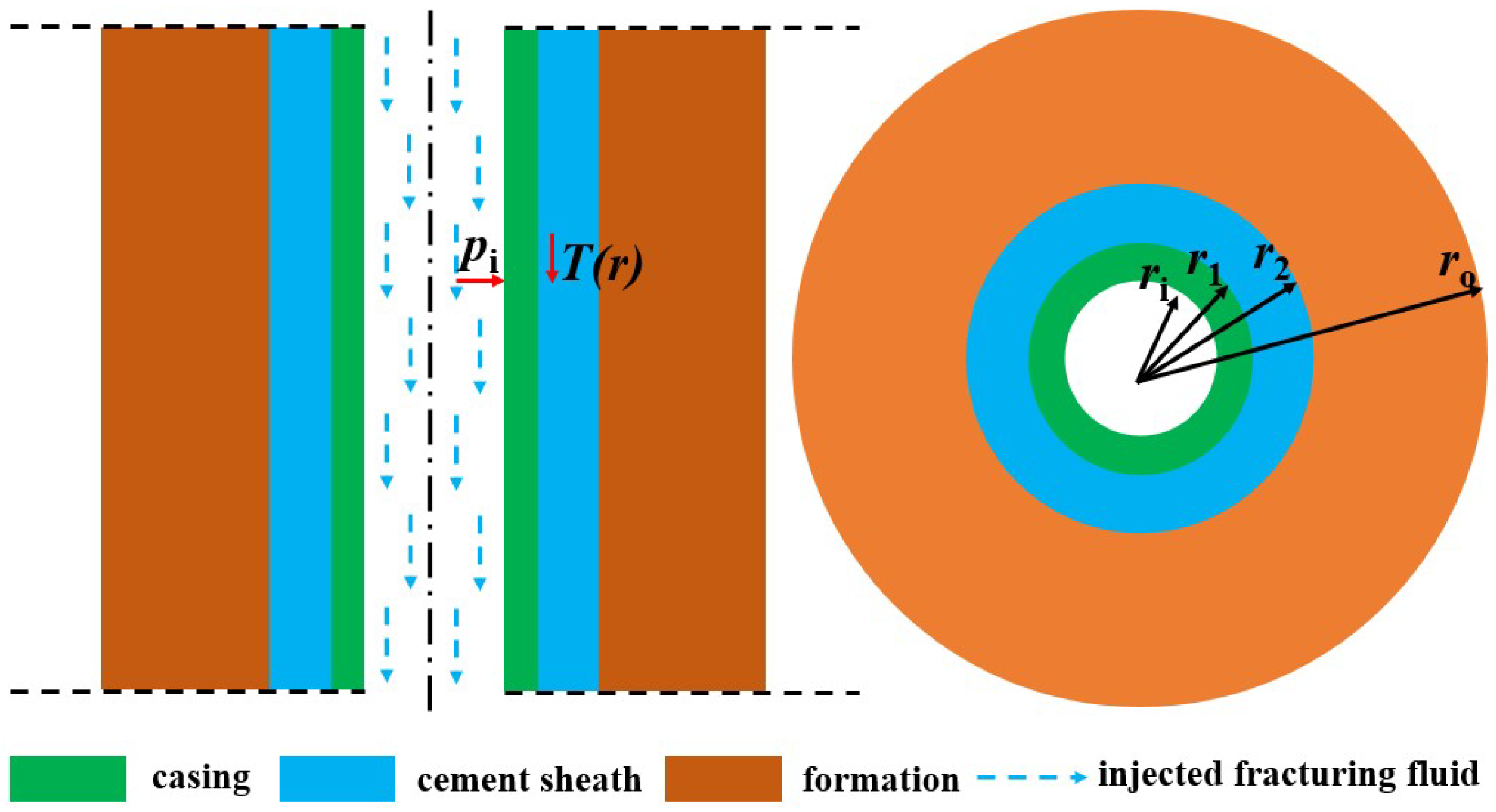
- The radial non-uniform temperature varies along the combined casing-cement sheath -formation system except for casing as consideration of its thin wall and well heat conduction performance.
- (5)
- The temperature at the inner wall of casing is equal to the wellbore fracturing fluid temperature and that at the outer wall of formation maintains an original formation temperature during fracturing.
2.2. Cement Sheath Stress Induced by the Decrease of Wellbore Temperature
2.3. Cement Sheath Stresses Induced by the Increase of Casing Pressure
2.4. Combined Stresses of Cement Sheath during Fracturing Fluid Injection
2.5. Failure Criterion and Safety Factor for Cement Sheath
3. Mechanical Integrity Analysis of Cement Sheath during Fracturing Fluid Injection
3.1. Basic Calculation Parameters
3.2. Results and Discussion
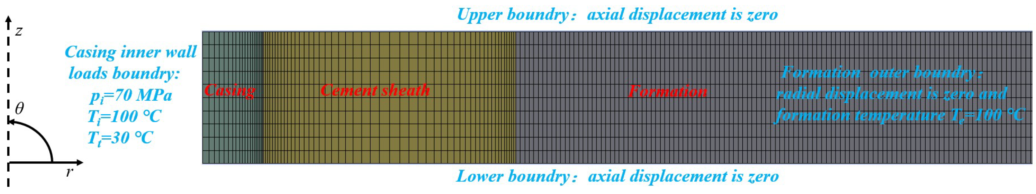
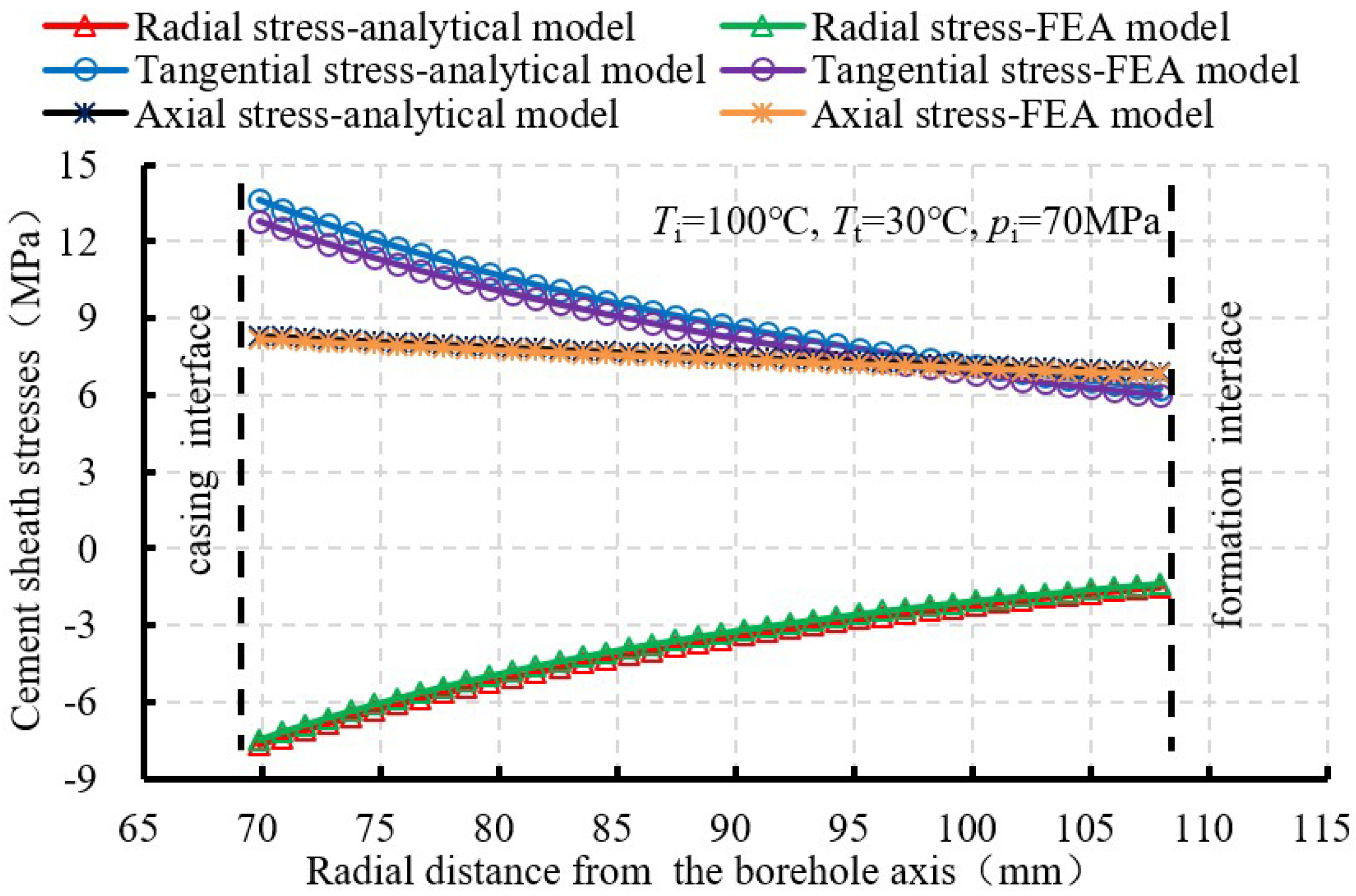
3.2.1. Cement Sheath Stresses Validated by the FEA Method
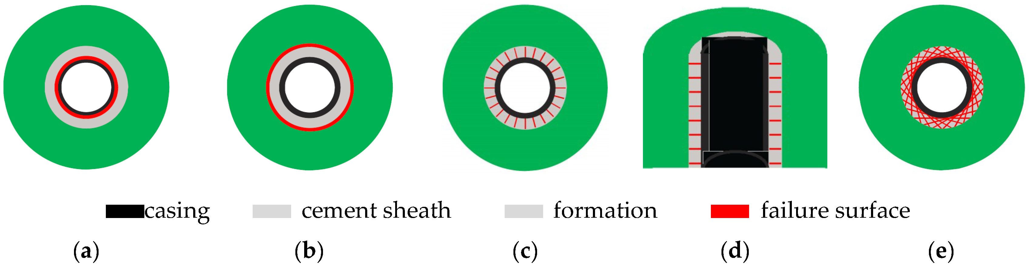
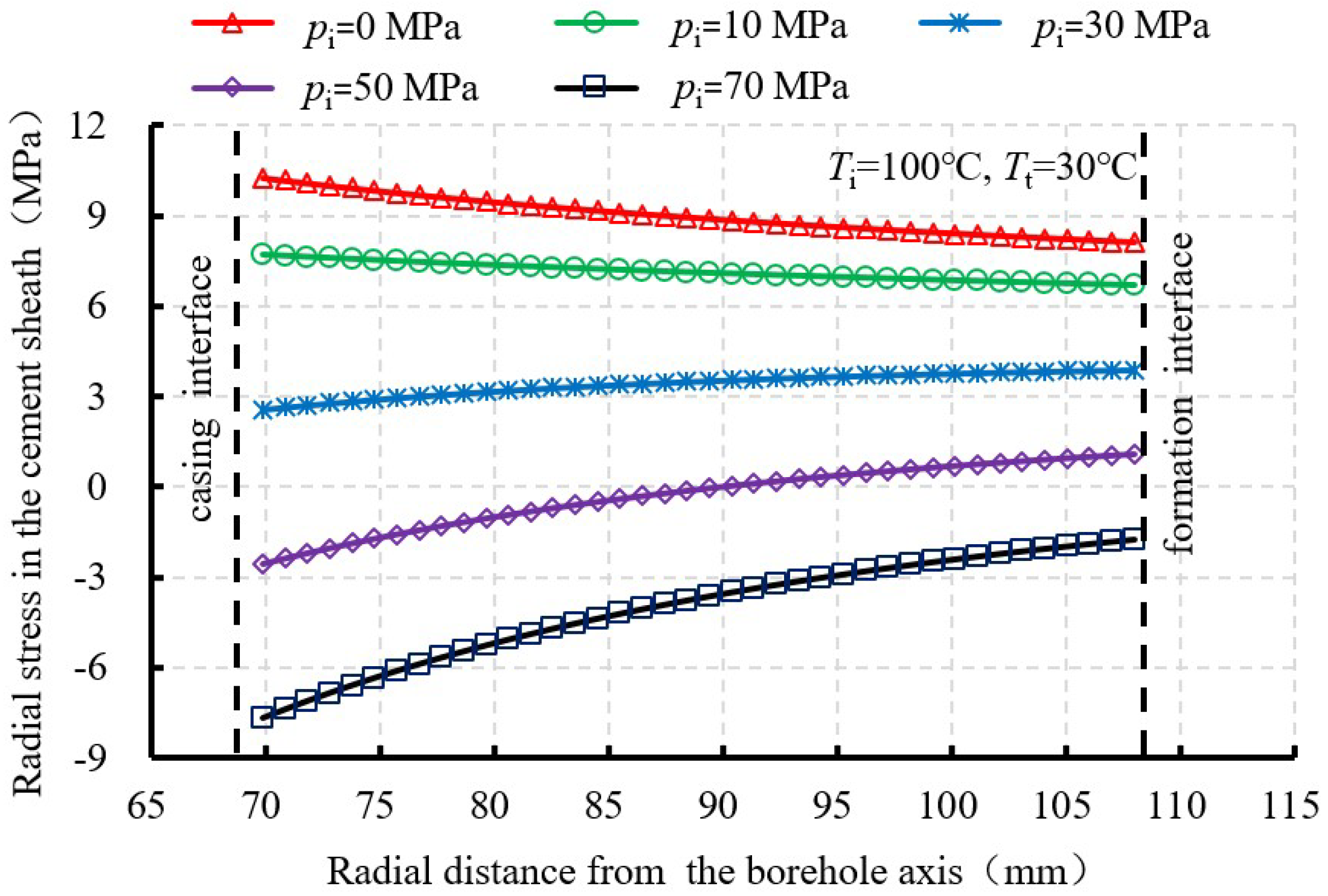
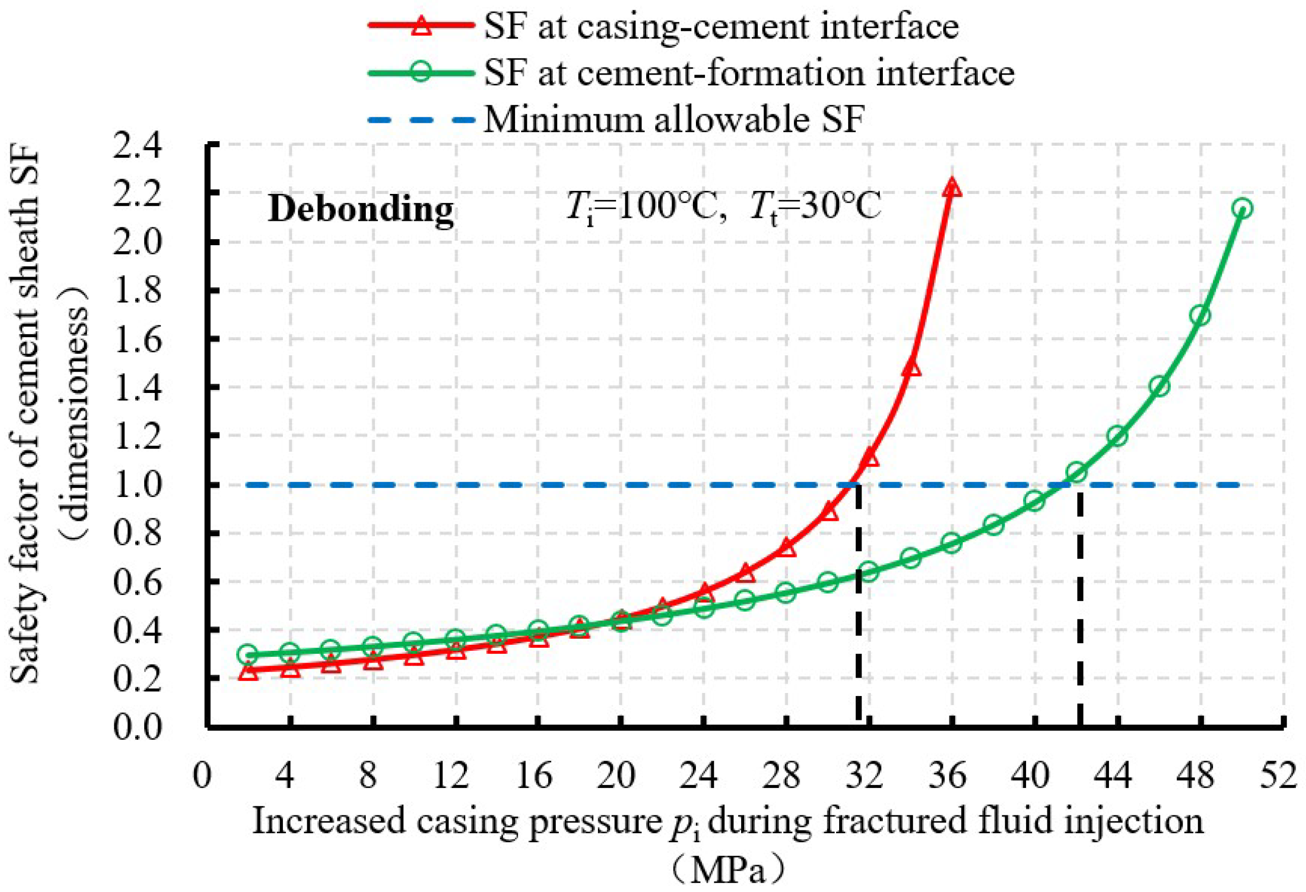
3.2.2. De-Bonding
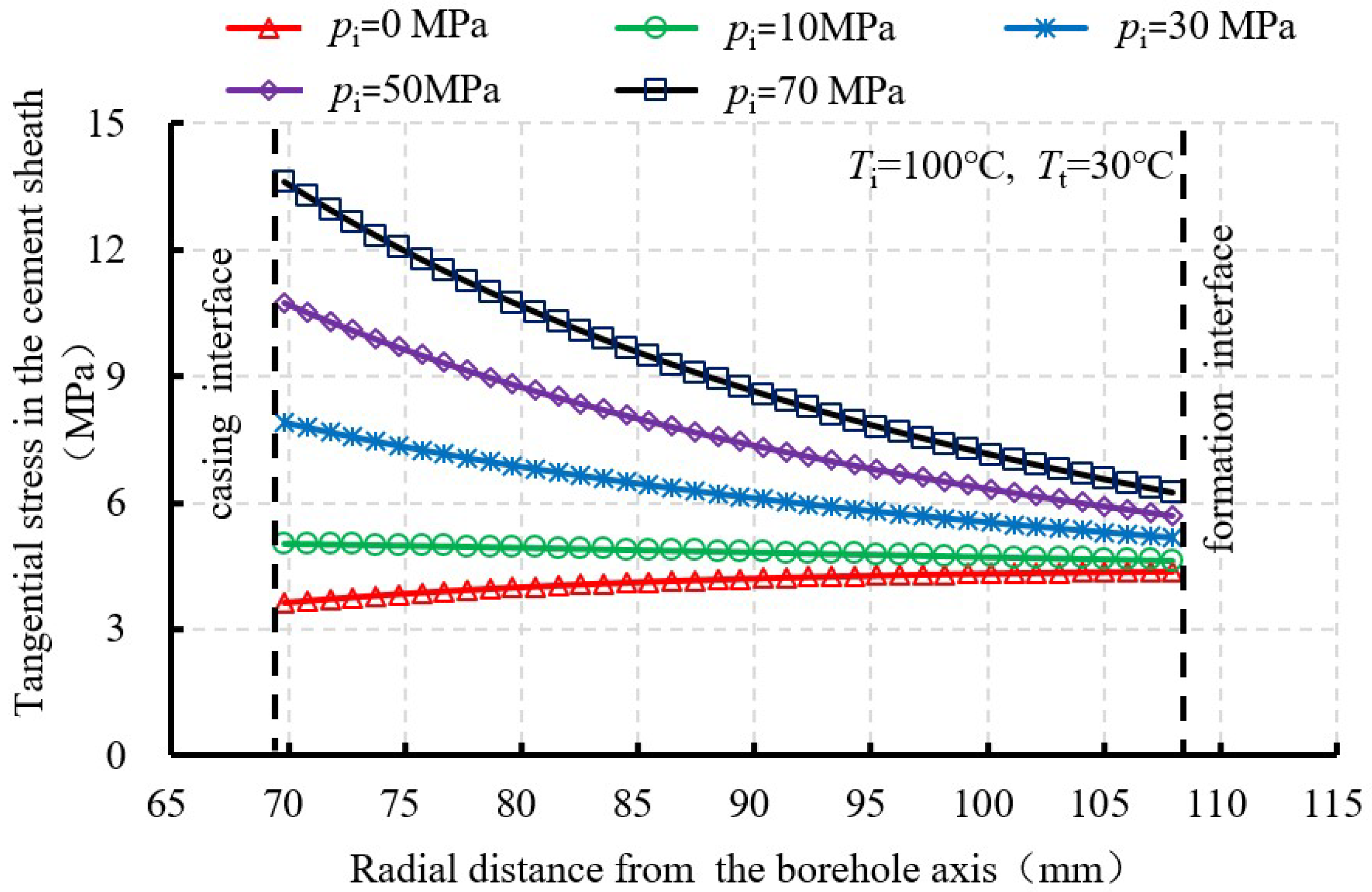
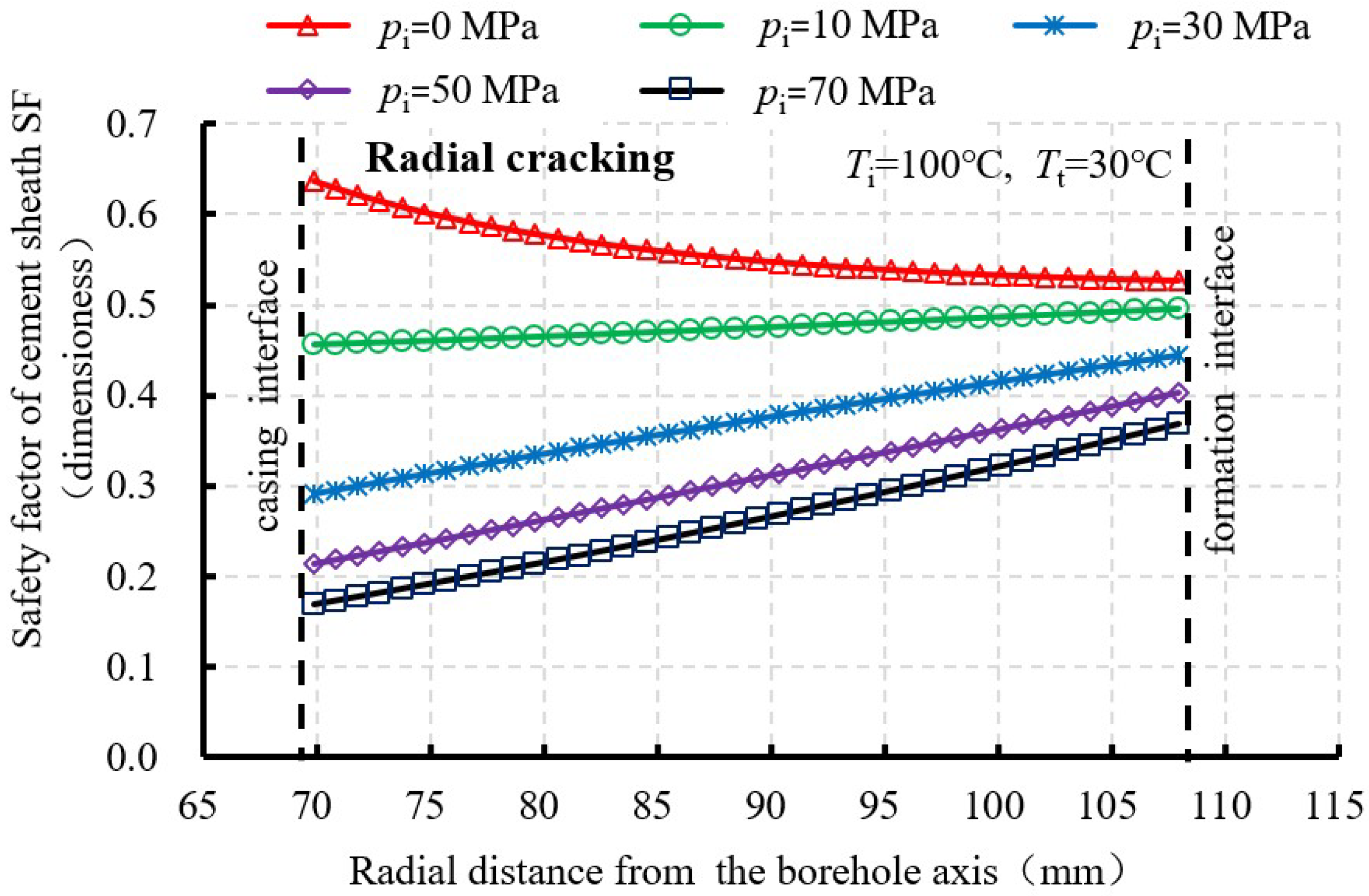
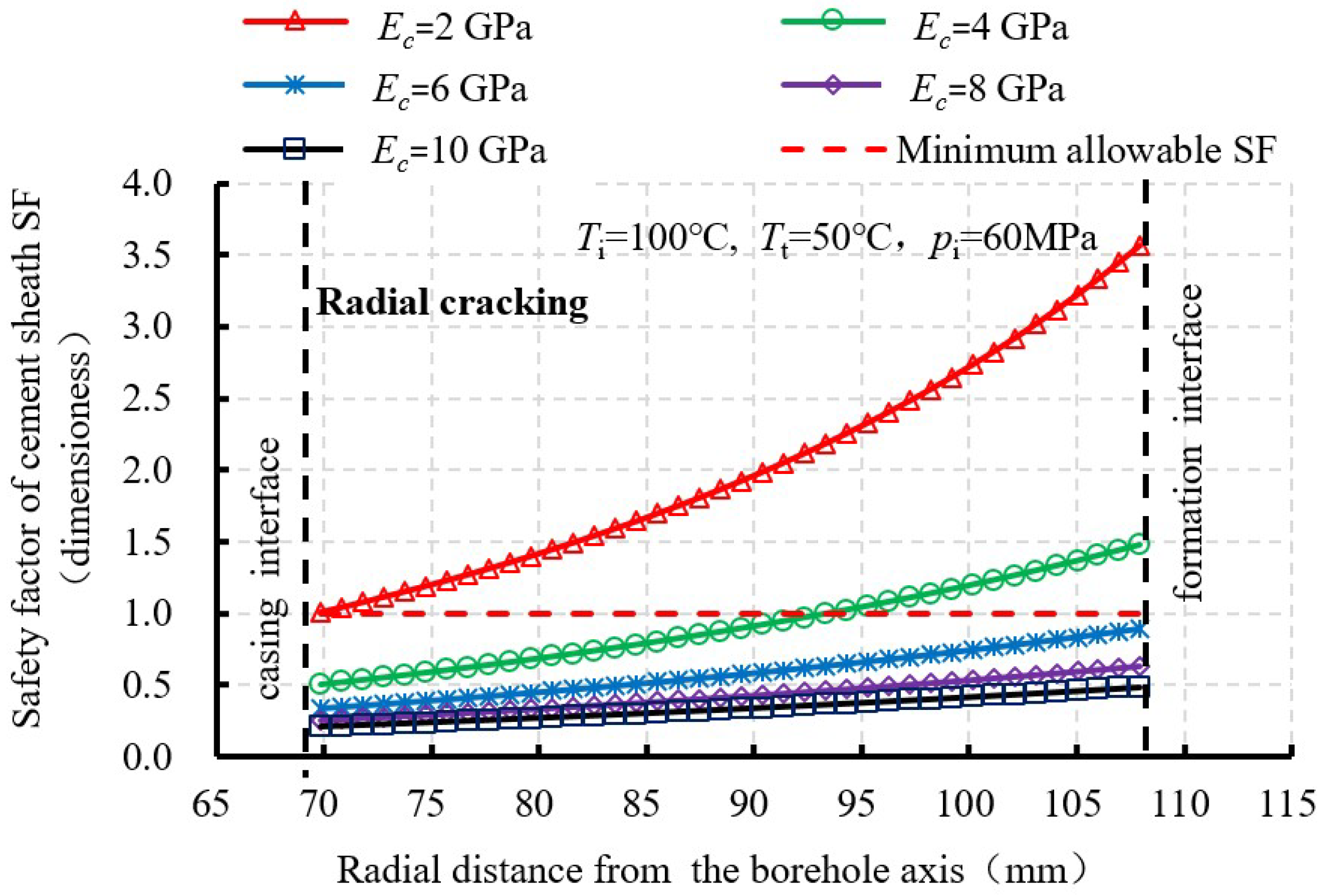
3.2.3. Radial Cracking
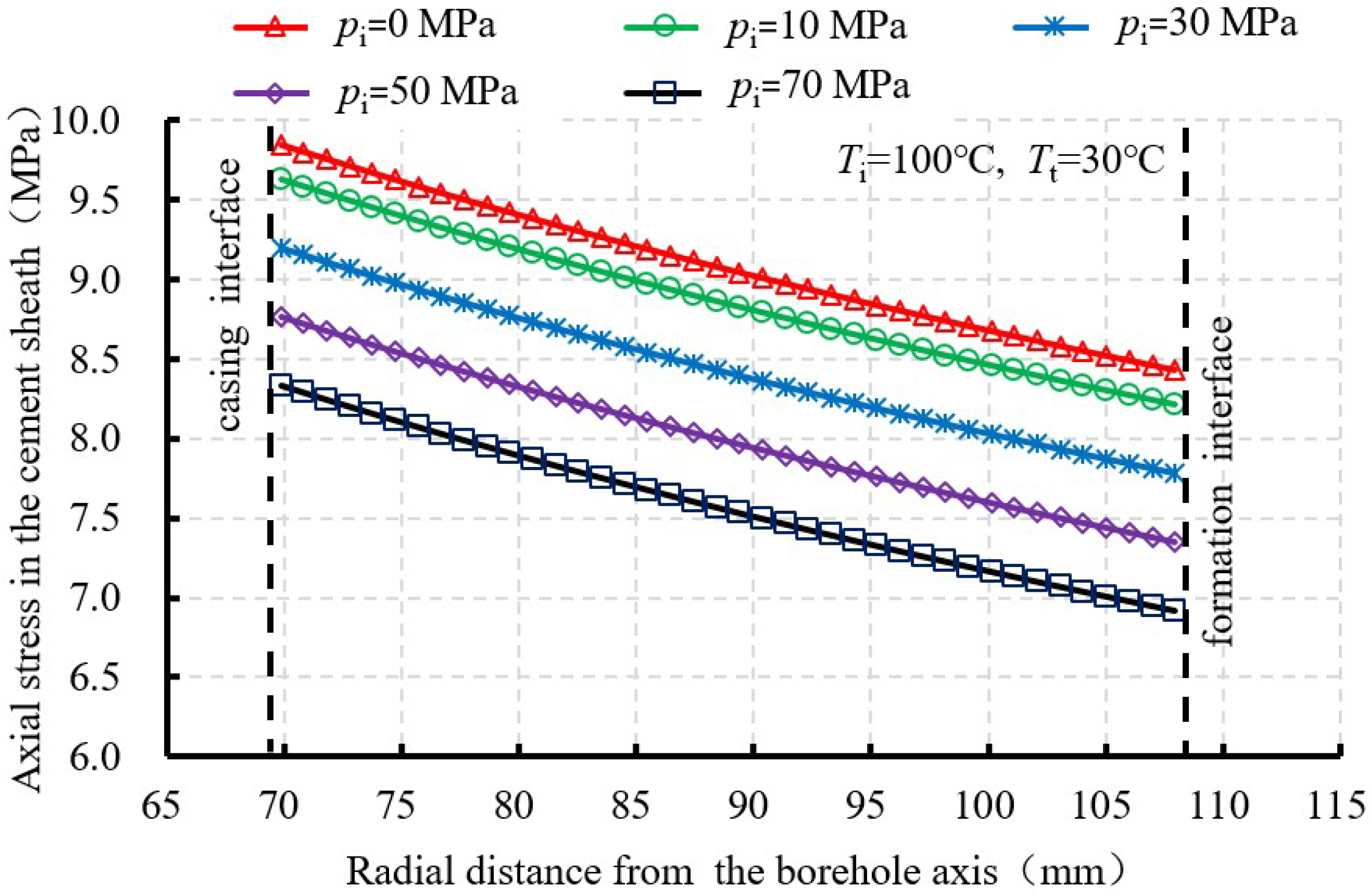
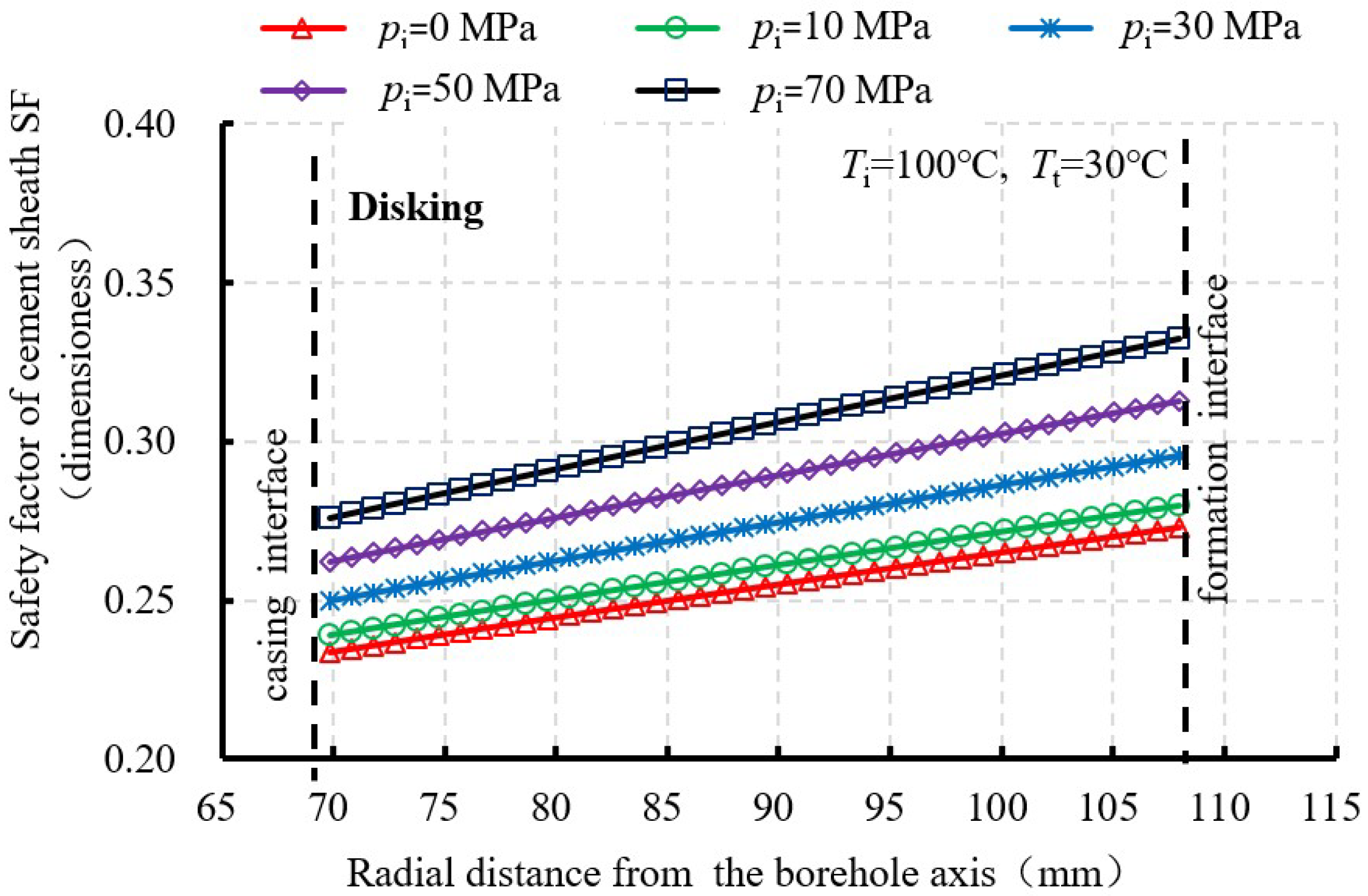
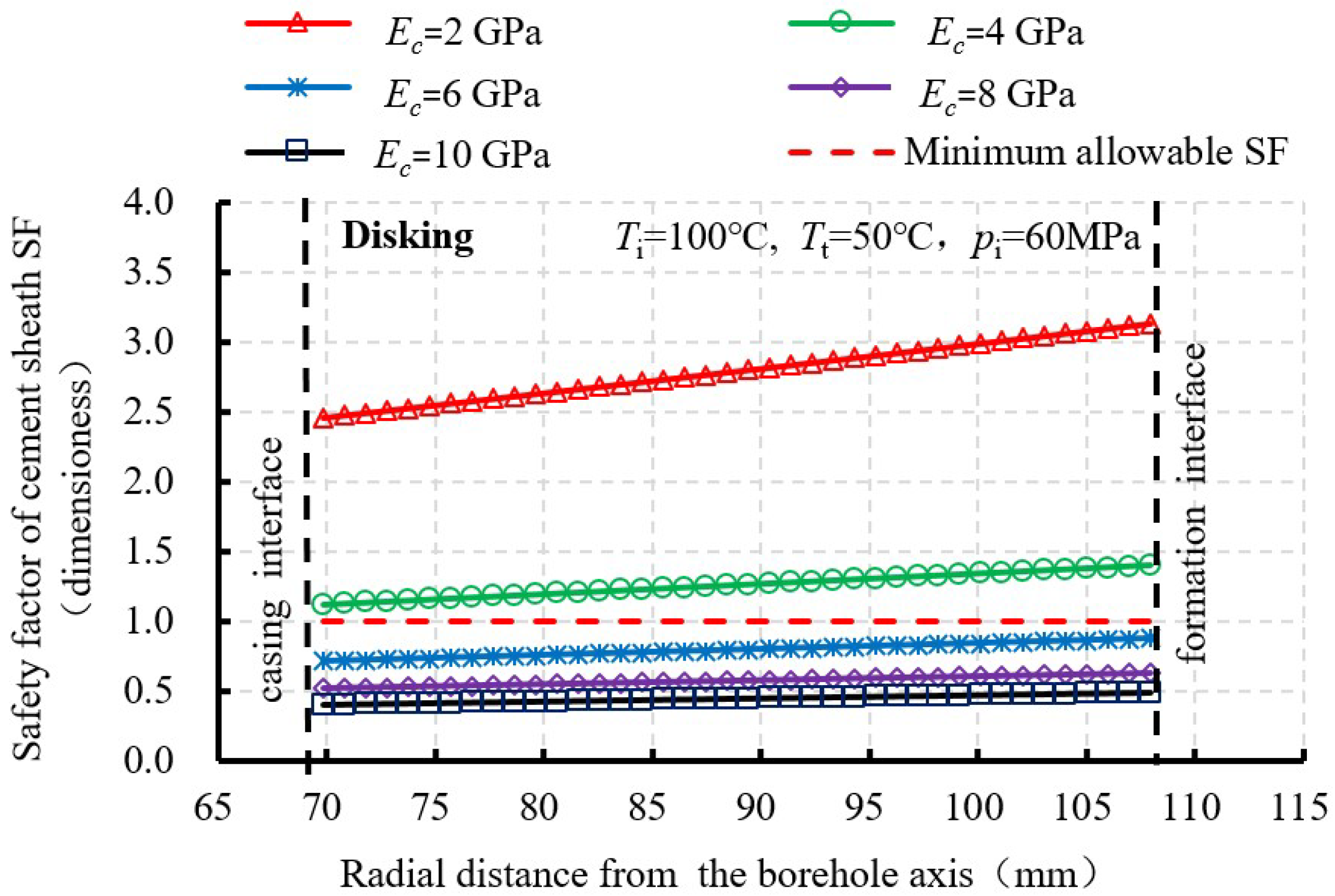
3.2.4. Disking
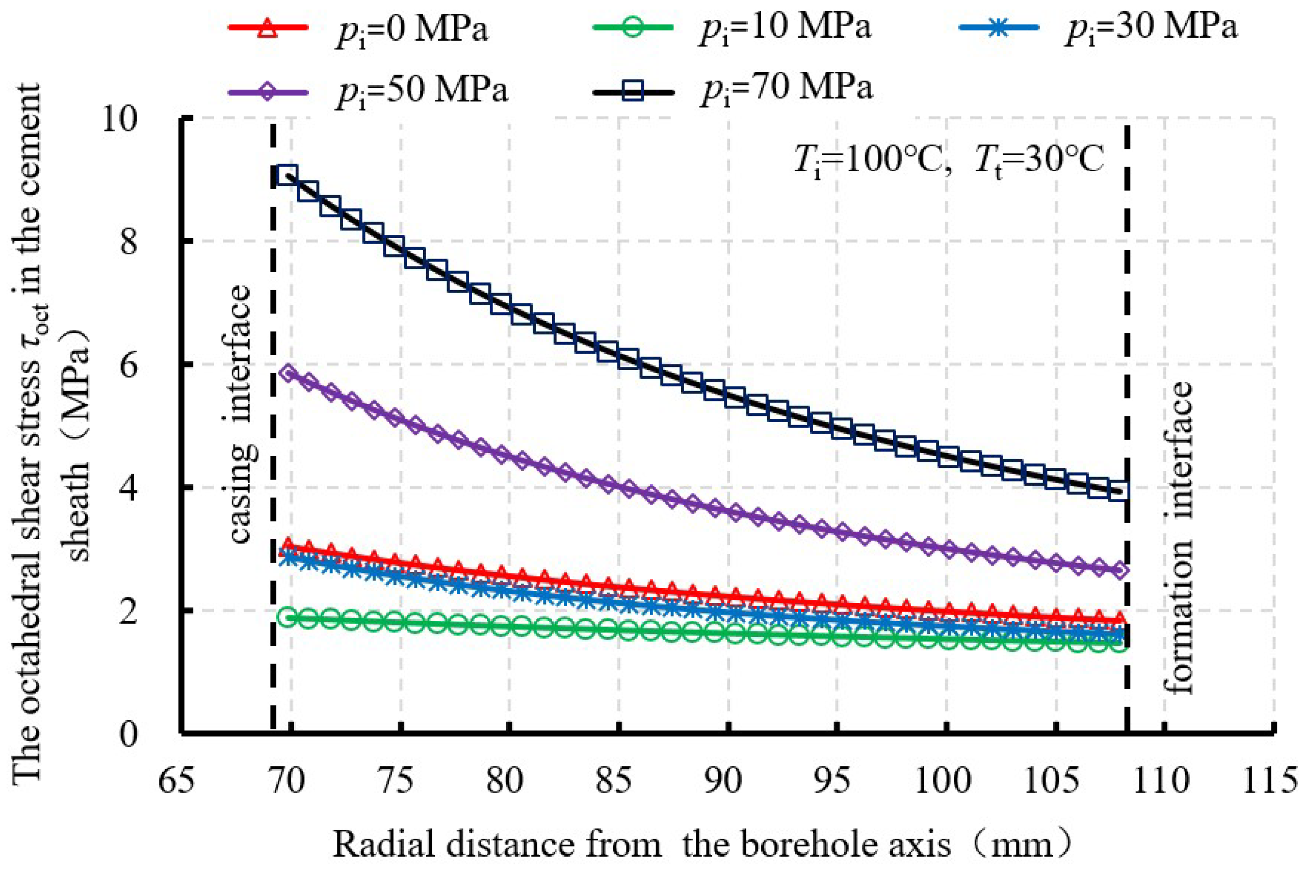
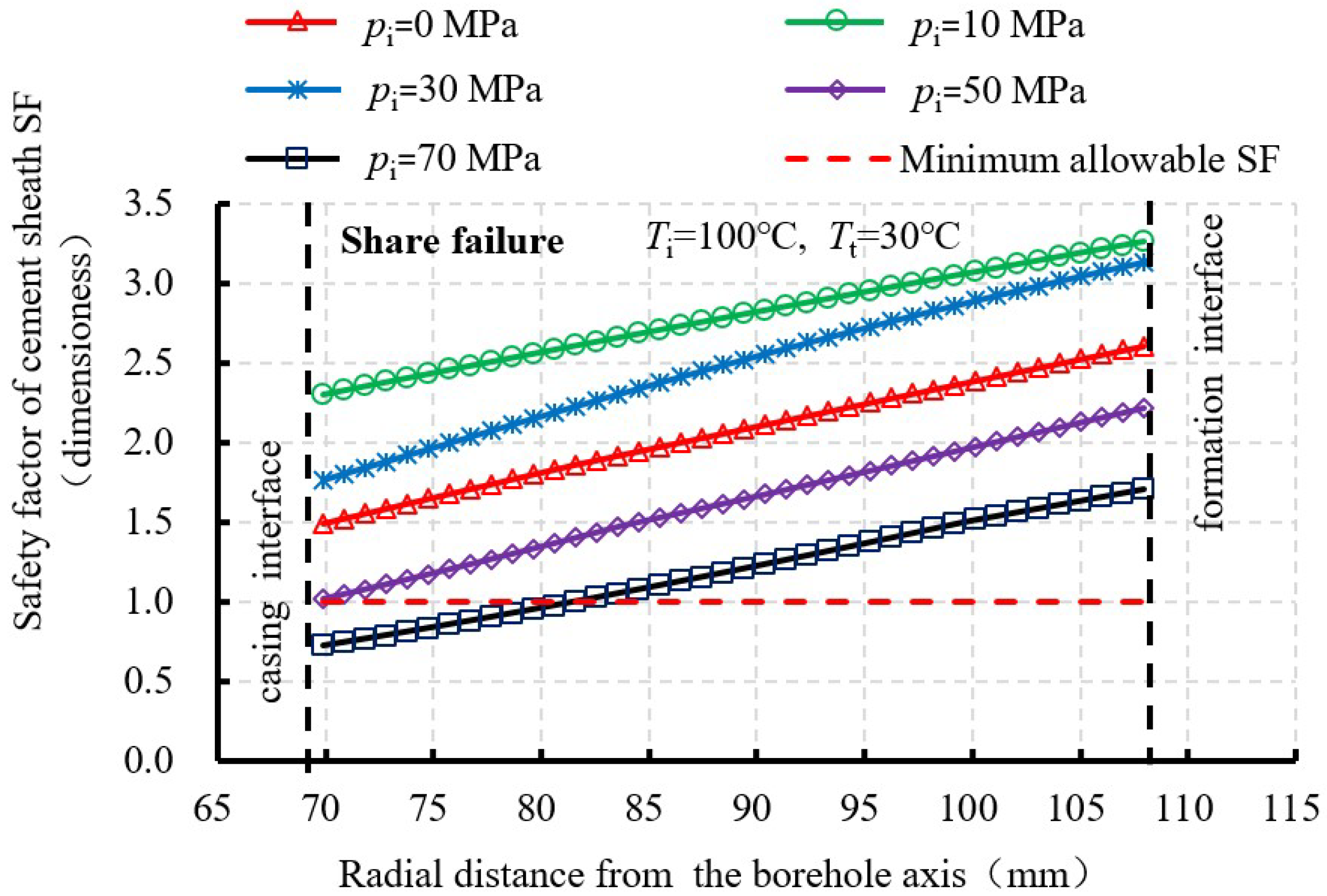
3.2.5. Shear Failure
3.3. Comparison and Discussion
4. Conclusions
- (1)
- The radial distributions of failure stresses and corresponding safety factors for cement sheath have been analyzed under four failure modes, including de-bonding, radial cracking, disking, and shear failure.
- (2)
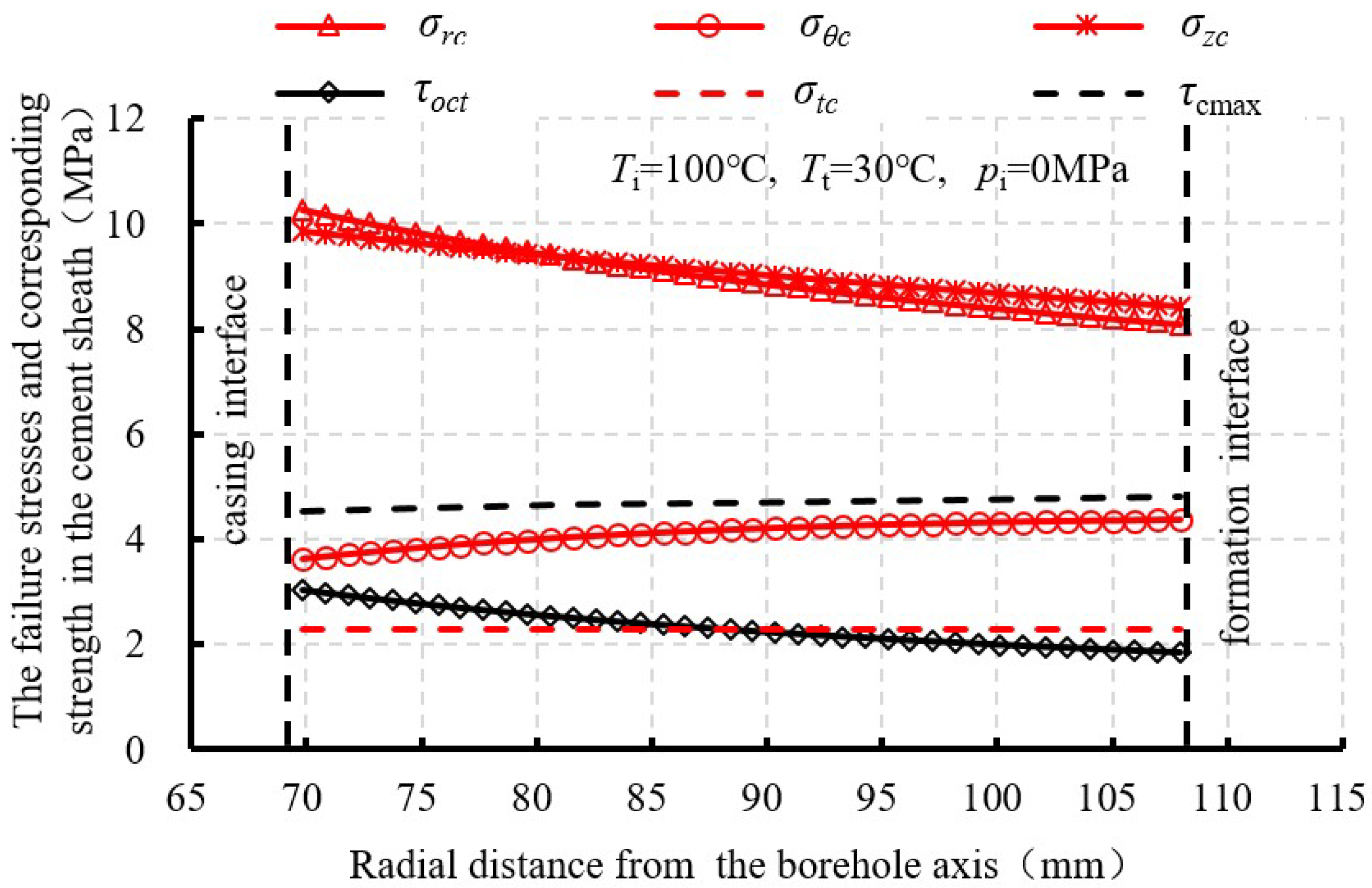
- The decreased wellbore temperature will produced significant tri-axial tensile stress and induce cement failure of de-bonding, radial cracking, and disking.
- (3)
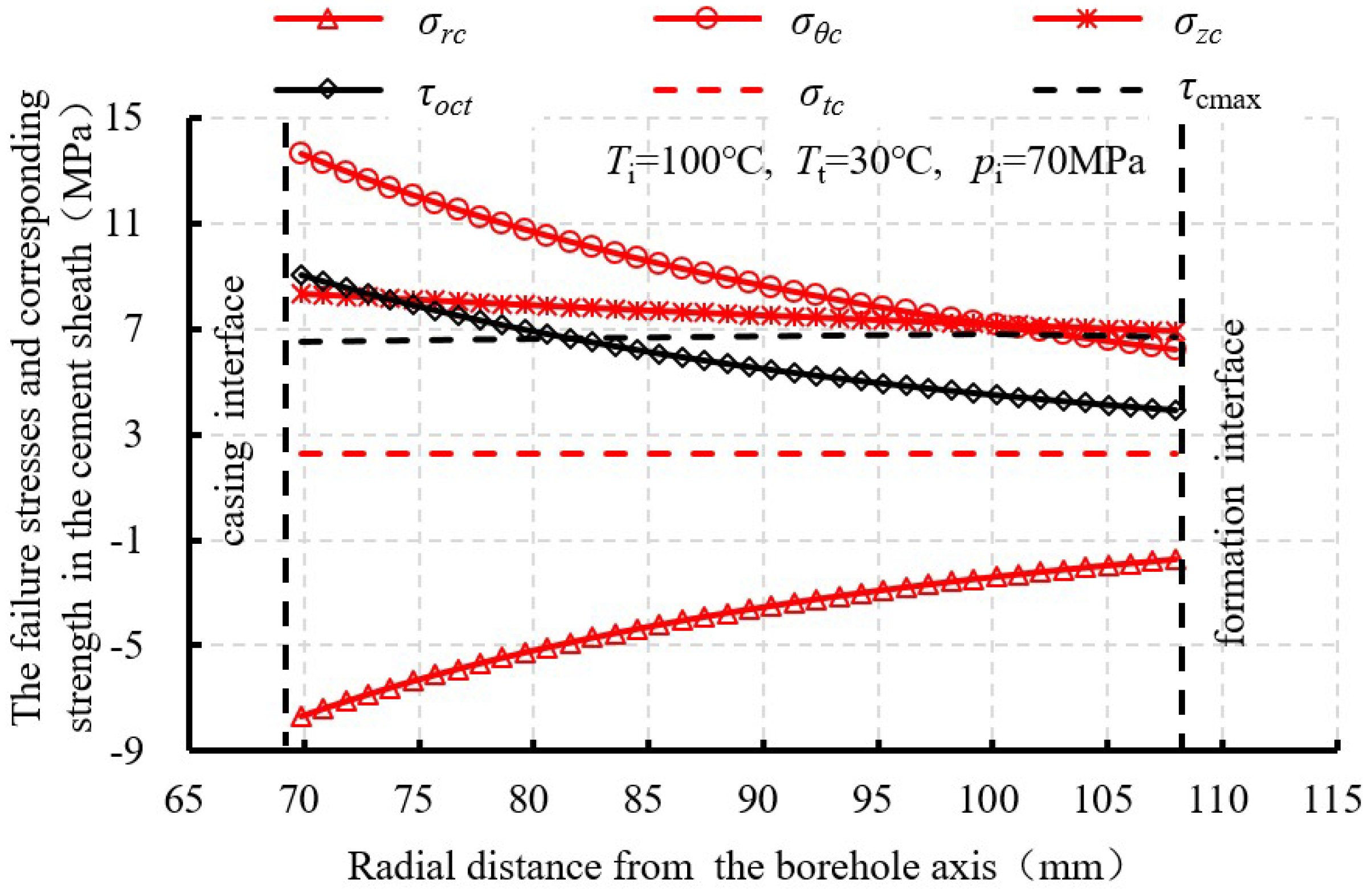
- The increased casing pressure will significantly lower the risk of de-bonding but also aggravate radial cracking and shear failure.
- (4)
- Increasing the injected fluid temperature, maintaining a higher circulation pumping pressures and adopting cement sheath with a low elasticity modulus can protect cement sheath in fracturing wells.
- (5)
- Considering some assumptions before model development, some conclusions may not be entirely appropriate. Further model improvement including casing centralization, anisotropy of the formation stresses, and a transient wellbore temperature change should be investigated.
Author Contributions
Funding
Conflicts of Interest
List of Symbols
| , , | Radial, tangential, and axial thermal stress of cylinder, respectively, MPa |
| , , | Radial, tangential, and axial stress of cylinder caused by increased inner pressure, respectively, MPa |
| , , | Radial, tangential, and axial thermal stress of casing, respectively, MPa |
| , , | Radial, tangential, and axial thermal stress of cement sheath, respectively, MPa |
| , , | Radial, tangential, and axial thermal stress of formation, respectively, MPa |
| , , | Radial, tangential, and axial stress of casing caused by increased casing pressure, respectively, MPa |
| , , | Radial, tangential, and axial stress of cement sheath caused by increased casing pressure, respectively, MPa |
| , , | Radial, tangential, and axial stress of formation caused by increased casing pressure, respectively, MPa |
| , σθc, | Combined radial, tangential, and axial stress of cement sheath caused by decreased wellbore temperature and increased casing pressure during fracturing fluid injection, respectively, MPa |
| σ1, σ2, σ3 | Maximum, intermediate, and minimum principal stresses in the cement sheath, respectively, MPa |
| uT | Radial thermal displacement in the cylinder, mm |
| uP | Radial displacement in the cylinder caused by increased inner pressure, mm |
| , , | Radial thermal displacement for casing, cement sheath, and formation, respectively, mm |
| , , | Radial displacement caused by increased casing pressure for casing, cement sheath, and formation, respectively, mm |
| E, Es, Ec, Ef | Elasticity modulus of ordinary cylinder, casing, cement sheath, and formation, respectively, MPa |
| μ, μs, μc, μf | Poisson’s ratio of ordinary cylinder, casing, cement sheath, and formation, respectively, dimensionless |
| α, αs, αc, αf | Linear thermal expansion coefficient of ordinary cylinder, casing, cement sheath, and formation, respectively, 1/°C |
| a | Internal radius of thick wall cylinder, mm |
| r | Radial distance from the axis of wellbore, mm |
| ri | Inside radius of casing, mm |
| r1 | Outside radius of casing or inside radius of cement sheath, mm |
| r2 | Outside radius of cement sheath or inside radius of formation, mm |
| ro | Outside radius of formation, mm |
| T(r) | Temperature change value at the radius of r after fracturing fluid injection, °C |
| Ti | Wellbore temperature before fracturing fluid injection, °C |
| Tt | Wellbore temperature after fracturing fluid injection, °C |
| Te | Formation temperature, °C |
| C1, C1s, C1c, C1f | Undetermined coefficients, dimensionless |
| C2, C2s, C2c, C2f | Undetermined coefficients, m2 |
| [A], {B} | Coefficient matrix and constant vector for Equation (A5), respectively |
| σtc | Tensile strength of cement sheath, MPa |
| σcc | Uniaxial compressive strength of cement sheath, MPa |
| τcmax | The maximum allowable shear stress for cement sheath, MPa |
| τoct | Octahedral shear stress, MPa |
| cc | Cohesion of cement sheath, MPa |
| ϕc | Angle of internal friction of cement sheath, (°) |
| pi | Increased casing pressure, MPa |
| pc1 | Contact pressure at the casing-cement sheath interface induced by increased casing pressure, MPa |
| pc2 | Contact pressure at the cement sheath-formation interface induced by increased casing pressure, MPa |
| pf | Changed formation pressure, MPa |
| SF | Safety factor of cement sheath, dimensionless |
Appendix A. Cement Sheath Stress Induced by a Decrease of Wellbore Temperature
References
- Shadravan, A.; Schubert, J.; Amani, M.; Teodoriu, C. HPHT cement sheath integrity evaluation method for unconventional wells. In Proceedings of the SPE International Conference on Health, Safety, and Environment, Long Beach, CA, USA, 17–19 March 2014. [Google Scholar]
- Wang, W.; Taleghani, A.D. Cement sheath integrity during hydraulic fracturing: An integrated modeling approach. In Proceedings of the SPE Hydraulic Fracturing Technology Conference, The Woodlands, TX, USA, 4–6 February 2014. [Google Scholar]
- Vrålstad, T.; Skorpa, R.; Opedal, N.; Andrade, J.D. Effect of thermal cycling on cement sheath integrity: Realistic experimental tests and simulation of resulting leakages. In Proceedings of the SPE Thermal Well Integrity and Design Symposium, Banff, AB, Canada, 23–25 November 2015. [Google Scholar]
- Thiercelin, M.J.; Dargaud, B.; Baret, J.F.; Rodriquez, W.J. Cement design based on cement mechanical response. SPE Drill. Complet. 1998, 13, 266–273. [Google Scholar] [CrossRef]
- Jing, L.I.; Lin, C.Y.; Yang, S.C.; Zhi, Y.; Chen, S. Theoretical solution of thermal stress for casing-cement-formation coupling system. J. China Univ. Pet. 2009, 33, 63–69. [Google Scholar]
- Li, Y.; Liu, S.; Wang, Z.; Yuan, J.; Qi, F. Analysis of cement sheath coupling effects of temperature and pressure in non-uniform in-situ stress field. In Proceedings of the International Oil and Gas Conference and Exhibition in China, Beijing, China, 8–10 June 2010. [Google Scholar]
- Bois, A.P.; Garnier, A.; Galdiolo, G.; Laudet, J.B. Use of a mechanistic model to forecast cement-sheath integrity for CO2 storage. In Proceedings of the SPE International Conference on CO2 Capture, Storage, and Utilization, New Orleans, LA, USA, 10–12 November 2010. [Google Scholar]
- Haider, M.G.; Sanjayan, J.; Ranjith, P.G. Modeling of a wellbore composite cylinder system for cement sheath stress analysis in geological sequestration of CO2. In Proceedings of the 46th U.S. Rock Mechanics/Geomechanics Symposium, Chicago, IL, USA, 24–27 June 2012. [Google Scholar]
- Bui, B.T.; Tutuncu, A.N. Modeling the failure of cement sheath in anisotropic stress field. In Proceedings of the SPE Unconventional Resources Conference Canada, Calgary, AB, Canada, 5–7 November 2013. [Google Scholar]
- Xi, Y.; Li, J.; Liu, G.H.; Zha, C.Q.; Yan, P. Analysis on cement sheath integrity under transient thermo-mechanical coupling effect. Oil Drill. Prod. Technol. 2017, 39, 417–423. [Google Scholar]
- Xu, H.; Zhang, Z.; Shi, T.; Xiong, J.Y. Influence of the WHCP on cement sheath stress and integrity in HTHP gas well. J. Pet. Sci. Eng. 2015, 126, 174–180. [Google Scholar]
- Xu, H.; Peng, N.; Ma, T.; Yang, B. Investigation of thermal stress of cement sheath for geothermal wells during fracturing. Energies 2018, 11, 2581. [Google Scholar] [CrossRef]
- Xu, B.; Wang, J. Theory of Elastic Mechanics; Tsinghua University Press: Beijing, China, 2007. [Google Scholar]
- Bois, A.P.; Garnier, A.; Galdiolo, G.; Laudet, J.B. Use of a mechanistic model to forecast cement-sheath integrity. SPE Drill. Complet. 2012, 27, 303–314. [Google Scholar] [CrossRef]
- Al-Ajmi, A.M.; Zimmerman, R.W. Relation between the Mogi and the Coulomb failure criteria. Int. J. Rock Mech. Min. Sci. 2005, 42, 431–439. [Google Scholar] [CrossRef]
- Ma, T.S.; Chen, P.; Yang, C.H.; Zhao, J. Wellbore stability analysis and well path optimization based on the breakout width model and Mogi-Coulomb criterion. J. Pet. Sci. Eng. 2015, 135, 678–701. [Google Scholar] [CrossRef]
- Nelson, E.B.; Guillot, D. Well Cementing, 2nd ed.; Schlumberger: Amsterdam, The Netherlands, 2006. [Google Scholar]
- Jaeger, J.C.; Cook, N.G.W.; Zimmerman, R.W. Fundamentals of Rock Mechanics, 4th ed.; Blackwell Publishing: Hoboken, NJ, USA, 2007. [Google Scholar]
- Andrade, J.D. Cement Sheath Integrity during Thermal Cycling. Ph.D. Thesis, Norwegian University of Science and Technology, Trondheim, Norway, 2015. [Google Scholar]
- Li, Q.; Wang, N. Numerical Analysis; Tsinghua University Press: Beijing, China, 2008. [Google Scholar]


| Failure Mode | Failure Criterion | Safety factor (SF) |
|---|---|---|
| Inner de-bonding | ||
| Outer de-bonding | ||
| Radial cracking | ||
| Disking | ||
| Shear failure |
| No. | Symbol | Value | Unite | No. | Symbol | Value | Unit |
|---|---|---|---|---|---|---|---|
| 1 | ri | 60.68 | mm | 11 | μs | 0.30 | dimensionless |
| 2 | r1 | 69.85 | mm | 12 | μc | 0.19 | dimensionless |
| 3 | r2 | 107.95 | mm | 13 | μf | 0.21 | dimensionless |
| 4 | ro | 1079.5 | mm | 14 | Ti | 100 | °C |
| 5 | αs | 1.15 × 10⁻⁵ | 1/°C | 15 | Tt | 30–70 | °C |
| 6 | αc | 1.03 × 10⁻⁵ | 1/°C | 16 | Te | 100 | °C |
| 7 | αf | 1.03 × 10⁻⁵ | 1/°C | 17 | pi | 0–70 | MPa |
| 8 | Es | 206 | GPa | 18 | σtc | 2.3 | MPa |
| 9 | Ec | 10 | GPa | 19 | σcc | 32 | MPa |
| 10 | Ef | 30 | GPa | 20 | φc | 30 | ° |
© 2018 by the authors. Licensee MDPI, Basel, Switzerland. This article is an open access article distributed under the terms and conditions of the Creative Commons Attribution (CC BY) license (http://creativecommons.org/licenses/by/4.0/).
Share and Cite
Xu, H.; Ma, T.; Peng, N.; Yang, B. Influences of Fracturing Fluid Injection on Mechanical Integrity of Cement Sheath under Four Failure Modes. Energies 2018, 11, 3534. https://doi.org/10.3390/en11123534
Xu H, Ma T, Peng N, Yang B. Influences of Fracturing Fluid Injection on Mechanical Integrity of Cement Sheath under Four Failure Modes. Energies. 2018; 11(12):3534. https://doi.org/10.3390/en11123534
Chicago/Turabian StyleXu, Honglin, Tianshou Ma, Nian Peng, and Bin Yang. 2018. "Influences of Fracturing Fluid Injection on Mechanical Integrity of Cement Sheath under Four Failure Modes" Energies 11, no. 12: 3534. https://doi.org/10.3390/en11123534