1. Introduction
Wind turbines are always suffering aerodynamic loads, gravitational and inertial loads, actuation loads and so on. during their lifetime [
1]. The aerodynamic loads are the main source of fatigue loads in wind turbines. The asymmetrical loads caused by wind shear, tower shadow effects, turbulence and other factors will lead to fatigue damage of blades, towers, drive trains, etc. Veers pointed out that if innovative blade design and control methods could result in decreased aerodynamic loads, the fatigue loads of wind turbines would be significantly mitigated [
2]. That would be helpful to effectively reduce the cost per kilo-Watt hour (kWh) of wind power.
The aerodynamic loads active control technology could dynamically regulate the aerodynamic properties (such as change angle of attack or lift coefficients) of blades based on appropriate sensor inputs [
3], so active control methods, such as individual pitch control (IPC) and trailing edge flap control (TEFC), are more suitable for handling the complex and unsteady aerodynamics loads of wind turbines. Therefore, the IPC and TEFC are widely studied for their engineering prospects.
The IPC regulates the pitch angle of each blade, respectively, to improve the aerodynamic performance. Bossanyi designed an IPC controller for wind turbines, and found that the fatigue loads was reduced significantly when IPC was applied both in simulation and field tests on Controls Advanced Research Turbines (CART) [
4,
5]. Engelen found that the fatigue loads on the blades was reduced by up to 17% and the extreme loads in certain cases dropped 50% by using a multi-rotational mode IPC (higher harmonics control) [
6]. Houtzager found that IPC can significantly reduce the vibrations in the wind turbine structure with considerably less high-frequent control action [
7].
The TEFC can quickly adjust the aerodynamic properties of the blade by regulating the trailing edge flaps’ (TEFs) deflection angle. Gaunaa found that TEFC could reduce 10–14.5% of the fatigue equivalent damage loads (DELs) on the blade root moments in simulations, decrease 50–60% of standard deviation of the lift coefficient in wind tunnel tests, and reduce about 14% of the fatigue loads and 20% of the
frequency loads in field tests on the Vestas V27 wind turbine [
8,
9,
10]. Barlas found that the fatigue DELs of flap-wise moments were reduced 54% in simulation by TEFC, and a reduction of 50% is measured in wind tunnel experiments [
11]. Zhang and Yu found that the reduction of flap-wise root moments and tip deflections by using TEFC were up to 20.4% and 15.7% for the normal turbulence model (NTM); and up to 15.0% and 11.9% for the extreme turbulence model (ETM) [
12,
13].
Since IPC has the advantage of a wide regulation range and the disadvantage of slow response, IPC is considered more suitable to mitigate low frequency loads. TEFC has the characteristics of fast response and local control capability, which makes it more suitable to mitigate the high frequency loads. It therefore should be beneficial to use IPC and TEFC to complement each other. However, relevant studies combining IPC and TEFC are rarely reported. In this work, the proposed combined pitch and trailing edge flap control (CPFC) combining the IPC loop and TEFC loop and based on a loadfrequency division control algorithm is investigated. The effect of CPFC for loads mitigation is analyzed. The outline of this paper is as follows: in
Section 2, the sources of fatigue loads of wind turbines are briefly analyzed, and the aerodynamics model and structural model of wind turbines are briefly described. In
Section 3, the control strategy of CPFC is described in details. In
Section 4, the simulation case of CPFC is demonstrated, and the simulation results are discussed. The conclusions are presented in the final section.
2. The Fatigue Loads of Wind Turbines
2.1. The Sources of Fatigue Loads of Wind Turbines
Wind is highly variable, both geographically and temporally. With the large-scale development of wind turbines, the fatigue loads caused by wind variation will greatly increase with the increment of rotor swept area. The main factors that cause the fatigue loads of wind turbines are wind shear, tower shadow effect and turbulence.
Wind shear is known as the increase of mean wind speed with height [
14]. The wind shear can be described by a logarithmic power law profile as follows:
where
is the wind speed at the reference height of
, generally referred to the hub height;
is the wind speed at the height
;
is the empirical wind shear exponent, which relates to the ground roughness and the atmospheric stability. A conservative value specified by the IEC standard is generally given as
for normal onshore wind conditions.
The tower shadow effect refers to the wind speed reduction caused by towers blocking the air flow [
14]. The tower shadow effect is only valid for the region of
, where
is the azimuth angle. From potential flow theory, the stream function of wind around the tower can be derived by superposing a doublet on uniform flow as follows:
where
is the flow velocity in the
direction at the position of
;
is the uniform flow;
and
are the longitudinal and lateral coordinates with respect to the tower centre;
is the tower diameter at the position of
.
The wind shear and tower shadow effect of wind turbines are illustrated in
Figure 1.
Turbulence refers to wind speed fluctuations on a fast time scale [
15,
16]. The variation of turbulent wind speed generally obeys a Gaussian distribution. The turbulence intensity can be defined as:
where
is turbulence standard deviation,
is the mean wind speed.
2.2. The Aerodynamic Model and Structural Model of Wind Turbine
The aerodynamic loads of wind turbines can be computed by blade element momentum theory [
17]. Assuming that the wind turbine rotor consists of
B identical blades, a blade element span length is
dr, and the chord length is
c. The differential rotor thrust and differential rotor torque of annular radius of
r can be represented as follows:
where
is the density of the air;
is the relative wind speed;
Cl and
Cd are the lift coefficient and drag coefficient of the airfoil, respectively. Then the rotor thrust and rotor torque can be obtained by integrating the annular radius along the span direction.
The structural model of wind turbine considers the blades as flexible cantilevered beams [
17]. Appling the normal mode summation method, the deflection of the flexible beam can be presented as follows:
where
u(
z,t) is the lateral deflection of the distance
z along the beam;
ϕa(
z) is the normal mode shape for mode
a;
qa(
t) is their associated generalized coordinate.
The flexible beam motion at a specific natural mode can be written in matrix form as follows:
where
is the coefficient vector;
is the eigenvalues, which being the square of the natural frequency
. The generalized mass matrix
and generalized stiffness matrix
can be derived from the kinetic energy and potential energy of the beam [
18].
3. Combined Pitch and Trailing Edge Flap Control
The CPFC includes the IPC loop and TEFC loop, which are combined by the load frequency division control algorithm. The IPC loop is mainly used to mitigate low frequency loads, and the TEFC loop is mainly used to mitigate high frequency loads. The CPFC adopts both an azimuth angle feed-forward and a loads feedback control strategy for improving the control performance. The feed-forward control strategy should mitigate the asymmetrical loads caused by observable system input disturbances, such as variable azimuth angles and wind speed. The feedback control strategy should decrease the system output errors (asymmetrical loads) and the expected closed loop control value. The feed-forward control loop should provide beneficial compensation for the feedback control loop.
3.1. IPC Based on Azimuth Angle Feed-forward Control Strategy
3.1.1. The Collective Pitch Control
Generally, the collective pitch control (CPC) is used for regulating the rotor speed to limit the excess of wind power above rated wind conditions [
19]. By classical proportional-integral-derivative (PID) control law, the equation of pitch angle perturbation which is related to rotor speed perturbation can be represented as follows:
where
is the small perturbation of the blade pitch angle about operating point;
is the small perturbation of low-speed shaft rotational speed about reference speed;
is the low-speed shaft rotational acceleration;
NGear is the high-speed to low-speed gearbox ratio;
,
and
are the proportional, integral, and derivative gains of blade collective pitch controller, respectively. where
is the blade initial pitch angle.
3.1.2. IPC Based on Azimuth Angle Feed-Forward Control Strategy
Due to wind shear and tower shadow effect, the blade loads are strongly related to the azimuth angle of the blades. The IPC based on azimuth angle feed-forward control strategy should be used to mitigate loads caused by wind shear and tower shadow effects. This method uses the weight coefficients to regulate the pitch angle of each blade, respectively [
20,
21,
22]. For a three blades wind turbine, the weight coefficients can be represented as follows:
where
is the weighted wind speed of
blade [
15,
23]; the wind speed at radius
of each blade is using as weighting in this work,
Rb is the radius of the rotor; the weighted wind speed can be derived from the hub height wind speed by the wind shear and tower shadow effect model;
is the exponent coefficient, considering the aerodynamic torque is proportionate to the square of the equivalent wind speed, the value of
is used in this work.
In order to keep the power output consistent with CPC, the sum of weight coefficients have to equal to 3 for three blades wind turbines, which can be represented as follows:
Therefore, the pitch angle of
blade by IPC based on azimuth angle feed-forward control strategy can be represented as follows:
where
is the blade pitch angle by CPC.
3.2. The IPC Based on Loads Feedback Control Strategy
3.2.1. Multi-Blade Coordinate Transformation
The blade root bending moments of a wind turbine can be measured by optical strain gauge sensors, so they are usually used as signals for the loads feedback control strategy, but the blade root bending moments are generally expressed in blade rotating frames. This is a periodic linear time-varying system (LTV) and much more challenging to design controllers. The multi-blade coordinate transformation (MBC) or
d-
q axis transformation can convert the measured loads into a fixed hub frame [
24]. Then the single-input and single-output linear time-invariant (LTI) controller can be used to mitigate the
(per revolution) harmonic frequency loads.
Assuming that the azimuth angle
implies the first (reference) blade is vertically up. Then the azimuth angles of the three blades can be represented as follows:
The transformations from three rotating blades to hub fixed frame for
frequency components can be represented as follows:
where
is fixed frame referenced degrees of freedom, which is used to represent the
harmonics frequency components of rotor angular velocity.
The transformations from hub fixed frame back to three rotating blades for
frequency components can be represented as follows:
3.2.2. The IPC Based on Loads Feedback Control Strategy
The IPC based on loads feedback control strategy is mainly used to mitigate
frequency loads in this work. The
frequency component of blade root out-of-plane bending moments are scaled and filtered by a band-pass filter from strain gauge sensors. The transfer function of band-pass filter for
frequency component is defined as follows:
where
and
are frequency and damping for
frequency component of blade root bending moments. The
frequency components of blade root bending moments from three rotating blades to hub fixed frame can be represented as follows:
where
is the blade root bending moment
frequency component of
blade;
and
are the yaw component and tilt component of
frequency loads in hub fixed frame respectively.
The yaw component and tilt component of
frequency loads can be seen as almost independent. Then PID controllers can be used to regulate the yaw component and tilt component respectively. Since the control objective is to minimize the asymmetrical loads, the reference values are set to zero. By PID control law, the governing equations for the yaw component and tilt component of
frequency loads can be represented as follows:
where
and
are the blade pitch angles of yaw component and tilt component in the hub fixed frame respectively;
,
,
,
,
and
are the proportional, integral, and derivative gains of yaw component controller and tilt component controller by IPC respectively.
The phase lag caused by the filter should be compensated by add a small phase offset to blade azimuth angle. Then the pitch angles from hub fixed frame back to three rotating blades by IPC based on loads feed-back control strategy can be represented as follow:
where
is the pitch angle of
blade by IPC based on loads feed-back control strategy;
is the phase offset for
frequency component of blade root bending moment.
The pitch actuator is described by a second-order model in this work. The transfer function of actuators for IPC is defined as follows:
In order to describe how the anti-windup scheme should finally be implemented into the wind turbine, the pitch actuator model includes minimum and maximum pitch angle, maximum pitch rate.
3.3. The TEFC Based on Loads Feedback Control Strategy
The TEFC based on loads feedback control strategy is similar to the IPC. The TEFC is mainly used to mitigate
frequency loads in this work. The transfer function of band-pass filter for
frequency component is defined as follows:
where
and
are frequency and damping for
frequency component of blade root bending moments.
The
frequency component of blade root bending moments from three rotating blades to hub fixed frame can be represented as follows:
where
is the blade root bending moment
frequency component of
blade;
and
are the yaw component and tilt component of
frequency loads in hub fixed frame respectively.
Similar to the IPC, the governing equations for the yaw component and tilt component of
frequency loads can be represented as follows:
where
and
are the TEFs deflection angles of yaw component and tilt component in the hub fixed frame respectively;
,
,
,
,
and
are the proportional, integral, and derivative gains of yaw component controller and tilt component controller by TEFC respectively.
The TEFs deflection angles from hub fixed frame back to three rotating blades by TEFC can be represented as follows:
where
is the current TEF deflection angle of
blade;
is the phase offset for
frequency component of blade root bending moment.
The TEFs actuator is also described by a second-order model in this work. The transfer function of actuators for TEFC is defined as follows:
Similar to the pitch actuator model, the TEFs deflection actuator model includes minimum and maximum deflection angle, maximum deflection rate.
3.4. The CPFC Based on Load Frequency Division Control Strategy
The CPFC adopts load frequency division control algorithm to combine IPC loop and TEFC loop. The complete transfer function of IPC loop for
frequency can be represented as follows:
The complete transfer function of TEFC loop for
frequency can be represented as follows:
In this work, the IPC loop adopts both azimuth angle feed-forward control strategy and loads feedback control strategy. Then the current pitch angle is the sum of two components, which can be represented as follows:
The CPFC scheme is illustrated in
Figure 2.
4. Simulation and Discussion
4.1. The Reference Wind Turbine
4.1.1. Specifications of Reference Wind Turbine
The 5 MW reference wind turbine is described by Jonkman [
17]. The wind turbine under consideration is onshore, upwind, with three blades, variable speed and collective pitch controlled. Its design specifications are given in
Table 1.
4.1.2. The TEFs Aerodynamic Characteristics
Suppose that each blade is equipped with one TEF, mounted in the blade section with airfoil of NACA 64-618 profile. The TEFs extends for 30% of the blade span length, distributed on 66–96% of span-wise; and extends for 10% of the airfoil chord ratio [
25]. The TEFs configuration is illustrated in
Figure 3.
The aerodynamic characteristics of the NACA 64-618 airfoil with TEFs are calculated by XFOIL and extended by Airfoil Prep spreadsheets. The TEFs have a significant effect on the lift coefficients
, drag coefficients
and moment coefficients
. The lift coefficients of NACA 64-618 airfoil with TEFs as function of both angles of attack and TEFs deflection angles are shown in
Figure 4.
4.1.3. The Anti-Windup Scheme of Blades and TEFs
Considering the dynamic characteristics of blades and TEFs, the blade-pitch rate is limited to 8°/s in absolute value; and the minimum and maximum blade pitch angles are limited to [0°–90°]. The TEFs deflection rate is limited to 40°/s in absolute value; and the minimum and maximum TEFs deflection angles are limited to [−15°–+15°].
4.2. Simulation Environment
4.2.1. Simulation Platform
The simulation is carried out on the joint simulation platform of FAST code and MATLAB software. The FAST code is used to perform time marching simulation of aero-elastic response of wind turbines. The MATLAB software is used to implement the control strategy. The FAST code needs to modify and recompile for integrating TEFs interface. Then FAST code is used as S-function which is called by MATLAB software.
4.2.2. Design Loads Case
The design loads cases (DLC) focus on the wind turbines fatigue loads of normal power production, according to DLC 1.2 of IEC 61400-1 [
26]. The turbulent wind is assumed to belong to Class IIB, normal turbulence model (NTM) with Von Karman spectrum. The turbulence intensity
is 0.14 while the reference wind speed
is 42.5 m/s. The hub height mean wind speed is assumed to 20 m/s, and wind shear model with power law exponent is 0.2. The turbulent wind data are generated by turbulent-wind simulator Turbsim code. The hub height wind speed is shown in
Figure 5.
4.3. Results and Discussion
The simulation results by CPC, IPC and CPFC are demonstrated. The discussion is based on the results during simulation time of 100–160 s.
4.3.1. The Blade Root Bending Moments
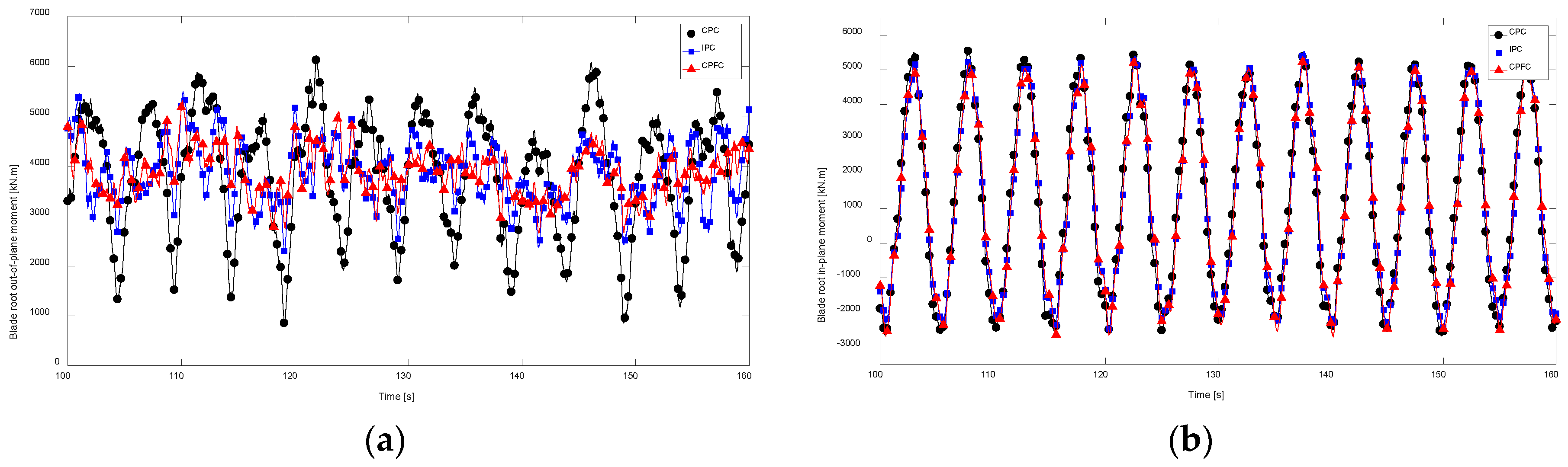
The blade 1 root bending moments of wind turbine by CPC, IPC, CPFC are shown in
Figure 6, and the details of standard deviation (Std) are given in
Table 2. As shown in
Figure 6a, the blade root out-of-plane bending moment (RootMyc1) fluctuates wildly by CPC. The fluctuation decreases significantly by IPC. The Std is reduced by 47.9% while using IPC. The fluctuation further decreases considerably by CPFC. The Std of moment is reduced by 55.3% while using CPFC. Since the fatigue loads are mainly caused by the fluctuation of aerodynamic loads, the reduction of fluctuation would helpful to mitigate the fatigue loads of wind turbines. As shown in
Figure 6b, the fluctuation of blade root in-plane bending moments (RootMxc1) just decrease slightly by IPC and CPFC, since it is not treated as a main control target in this work.
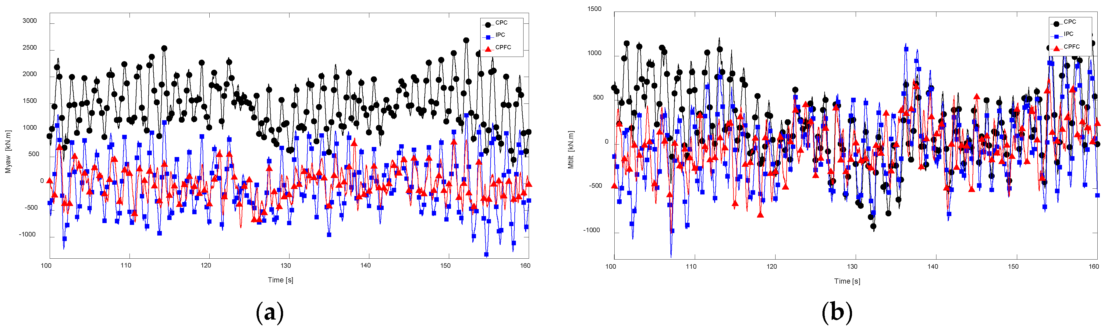
4.3.2. The Yaw Moments and Tilt Moments
The yaw moments (Myaw) and tilt moments (Mtilt) in hub fixed frame of wind turbine by CPC, IPC, CPFC are shown in
Figure 7, and the details of mean value and Std are given in
Table 3. The mean values of yaw moment and tilt moment decrease significantly by IPC. The mean values are respectively reduced by 99.7% and 94.8% while using IPC. The fluctuation of yaw moment and tilt moment decreases considerably by CPFC. The Std are respectively reduced by 29.9% and 22.1% while using CPFC. It indicates that IPC is helpful to reduce the asymmetrical loads and CPFC is helpful to mitigate the fatigue loads in hub frame.
4.3.3. The Blade Tip Deflections
The blade tip deflections of wind turbine by CPC, IPC and CPFC are shown in
Figure 8, and the details of Std are given in
Table 4. As shown in
Figure 8a, being compared to the Std of blade tip out-of-plane deflection (OoPDefl1) by CPC, the Std is reduced by 44.6% when using IPC, and it is further reduced by 50.2% when using CPFC. As shown in
Figure 8b, the Std of blade tip in-plane deflection (IPDefl1) is also decreased significantly when using IPC and CPFC.
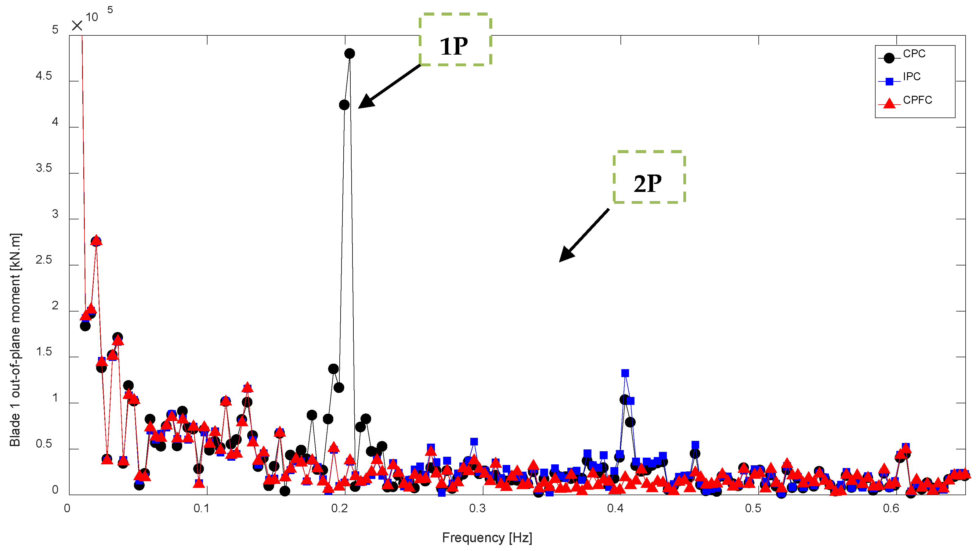
4.3.4. Power Spectral Density Analysis
The power spectral density (PSD) analysis of the blade root out-of-plane bending moment by CPC, IPC, CPFC are shown in
Figure 9. It can be seen that there are obvious peaks of
(about 0.2 Hz) and
(about 0.4 Hz) frequency load while using CPC. The
frequency peak is removed completely while using IPC. Both the
and
frequency peaks are removed completely when using CPFC. Since the IPC loop is mainly used to mitigate
frequency loads, and the TEFC loop is mainly used to mitigate
frequency loads. The results demonstrate conclusively that CPFC can mitigate fatigue loads as anticipated.
4.3.5. The Power Generation
The power generations of wind turbine by CPC, IPC, CPFC are shown in
Figure 10. There’s no noticeable difference between these control strategies. This indicates that IPC and CPFC have no significant impact on power generation when the wind speed exceeds the rated wind speed. The potential of enhanced power generation by CPFC also be widely studied. Smit’s research shows that smart rotors equipped with TEFs could increase the power generation below rated wind speed [
27]. However, the main objective is to mitigate loads in this work, so no deeply study on power generation.
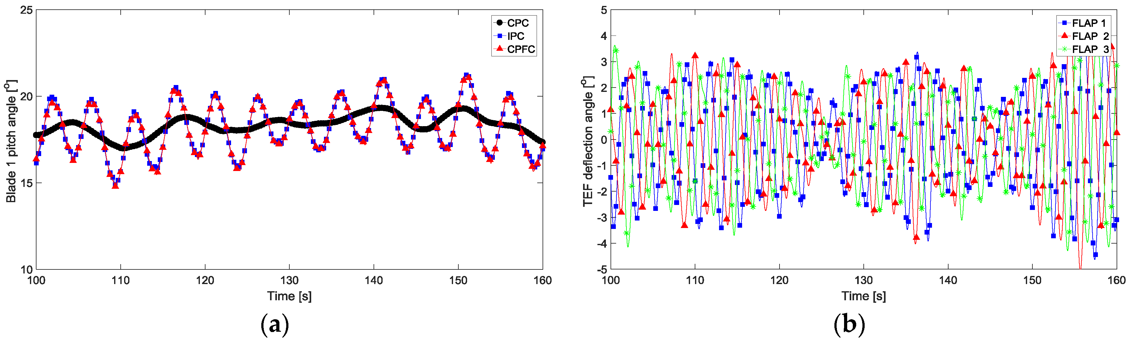
4.3.6. The Blade 1 Pitch Angles and TEFs Deflection Angles
The blade 1 pitch angles and TEFs deflection angles by CPC, IPC, CPFC are shown in
Figure 11. As seen in
Figure 11a, the pitch angle of blade 1 varies smoothly when using CPC. The pitch angle fluctuates around the CPC pitch angle at the
harmonics frequency when using IPC. This may cause increased pitch actuator duty to be required. The TEFC loop has no significant impact on pitch angle because it is not treated as a main control target in this work. As shown in
Figure 11b, The TEFs deflection angles of the three blades fluctuate at the
harmonic frequency for mitigating the
frequency loads. The loads mitigation control strategy of TEFs has not been optimized in this work. Therefore, the loads mitigation capability of TEFs could be further improved.
4.3.7. The Damage Equivalent Loads
The damage equivalent loads (DEL) of wind turbines are computed by the rain flow counting (RFC) algorithm [
28]. Accounting for the fatigue properties of the blade material, S-N slopes of 10 are used for composite materials. The equivalent frequency of the DEL is 1 Hz.
The fatigue DEL of wind turbine by CPC, IPC, CPFC are shown in
Figure 12; and the details of DEL are given in
Table 5. Compared to the DEL of blade root out-of-plane bending moment (RootMyc1) by CPC, the DEL are reduced by 42.2% when using IPC, and it is further reduced by 53.7% when using CPFC. The DEL of blade root in-plane bending moments (RootMyc1), yaw moments (Myaw) and tilt moments (Mtilt) also reduce in different degrees when using IPC and CPFC.
5. Conclusions
In this work, the CPFC for loads mitigation of wind turbines is investigated. The main conclusions are as follows:
(1) The IPC and CPFC could effectively mitigate the fatigue loads and decrease the structural deflections of wind turbines. Compared to CPC, the DEL of blade root out-of-plane bending moment is reduced by 42.2% while using IPC, and it is further reduced by 53.7% while using by CPFC. The standard deviation of blade tip out-of-plane deflection is reduced by 44.6% while usinig IPC, and it is further reduced by 50.2% while using CPFC.
(2) The CPFC could adopt a load frequency division control algorithm to combine the IPC loop and TEFC loop. The IPC loop is mainly used to mitigate low frequency loads, and the TEFC loop is mainly used to mitigate high frequency loads. Due to the fast response of TEFs, higher frequency loads can be further mitigated; and the combined control algorithm can be further optimized to enhance power generation and reduce excessive actuator action.
(3) The CPFC adopts both an azimuth angle feed-forward and a loads feedback control strategy for improving control performance. The feed-forward control loop should anticipate the observable disturbances and provide beneficial compensation for feedback control loop. The advanced predictive model control and wind speed measurement by LIDAR could further improve the controller performance.
(4) The power generation wind speed has no significant impact with CPFC while exceeding the rated. The effect of CPFC on power generation below rated wind speed should be further studied.
Author Contributions
Conceptualization and Methodology, K.H.; Software and Data curation, L.Q.; Investigation and Validation, L.Z.; Supervision and Funding acquisition, Y.C.
Acknowledgments
This work was supported by the National High-tech R&D Program of China (863 Program, Grant No. 2012AA051301), National Natural Science Foundation of China (Grant No. 51076088), Guangdong Science and Technology Planning Project (Grant No. 2015B020240003); Shantou Science and Technology Planning Project (Grant No. 2015-58; 2016-65).
Conflicts of Interest
The authors declare no conflict of interest.
References
- Veritas, D.N. Guidelines for Design of Wind Turbines, 2nd ed.; Risoe National Laboratory: Kongens Lyngby, Denmark, 2002; pp. 58–60. ISBN 87-550-2870-5. [Google Scholar]
- Veers, P.S.; Ashwill, T.D.; Sutherland, H.J.; Laird, D.L.; Lobitz, D. Trends in the design, manufacture and evaluation of wind turbine blades. Wind Energy 2003, 6, 245–259. [Google Scholar] [CrossRef]
- Barlas, T.K.; van Kuik, G.A.M. Review of state of the art in smart rotor control research for wind turbines. Prog. Aerosp. Sci. 2010, 46, 1–27. [Google Scholar] [CrossRef]
- Bossanyi, E.A. Individual blade pitch control for load reduction. Wind Energy 2003, 6, 119–128. [Google Scholar] [CrossRef]
- Bossanyi, E.; Savini, B.; Iribas, M.; Hau, M.; Fischer, B.; Schlipf, D.; Engelen, T.; Rossetti, M.; Carcangiu, C.E. Advanced controller research for multi-mw wind turbines in the UPWIND project. Wind Energy 2011, 15, 119–145. [Google Scholar] [CrossRef]
- Engelen, T.G. Design model and load reduction assessment for multi-rotational mode individual pitch control. In Proceedings of the European Wind Energy Conference, Athens, Greece, 27 February–2 March 2006. [Google Scholar]
- Houtzager, I.; van Wingerden, J.W.; Verhaegen, M. Wind turbine load reduction by rejecting the periodic load disturbances. Wind Energy 2012, 16, 235–256. [Google Scholar] [CrossRef]
- Bergami, L.; Poulsen, N.K. A smart rotor configuration with linear quadratic control of adaptive trailing edge flaps for active load alleviation. Wind Energy 2014, 18, 625–641. [Google Scholar] [CrossRef] [Green Version]
- Bak, C.; Gaunaa, M.; Andersen, P.B.; Buhl, T.; Hansen, P.; Clemmensen, K. Wind tunnel test on airfoil risø-b1-18 with an active trailing edge flap. Wind Energy 2010, 13, 207–219. [Google Scholar] [CrossRef]
- Castaignet, D.; Barlas, T.; Buhl, T.; Poulsen, N.K.; Wedel-Heinen, J.J.; Olesen, N.A.; Bak, C.; Kim, T. Full-scale test of trailing edge flaps on a vestas v27 wind turbine: active load reduction and system identification. Wind Energy 2013, 17, 549–564. [Google Scholar] [CrossRef]
- Barlas, T.K.; Wingerden, W.V.; Hulskamp, A.W. Smart dynamic rotor control using active flaps on a small-scale wind turbine: Aeroelastic modeling and comparison with wind tunnel measurements. Wind Energy 2013, 16, 1287–1301. [Google Scholar]
- Zhang, M.; Yu, W.; Xu, J. Aerodynamic physics of smart load control for wind turbine due to extreme wind shear. Renew. Energy 2014, 70, 204–210. [Google Scholar] [CrossRef]
- Yu, W.; Zhang, M.M.; Xu, J.Z. Effect of smart rotor control using a deformable trailing edge flap on load reduction under normal and extreme turbulence. Energies 2012, 5, 3608–3626. [Google Scholar] [CrossRef]
- Burton, T.; Jenkins, N.; Sharpe, D.; Bossanyi, E. Wind Energy Handbook, 2nd ed.; John Wiley & Sons: Hoboken, NJ, USA, 2011; pp. 14–28. ISBN 978-0-470-69975-1. [Google Scholar]
- Sørensen, P.; Hansen, A.D.; Rosas, P.A.C. Wind models for simulation of power fluctuations from wind farms. J. Wind Eng. Ind. Aerodyn. 2002, 90, 1381–1402. [Google Scholar] [CrossRef]
- Dou, Z.L.; Wang, H.; Zhang, Q.Q.; Liang, Z.B.; Cai, X. Experimental research on virtual wind farm and wind turbine emulator system. Proc. CSEE 2011, 31, 127–135. [Google Scholar]
- Jonkman, J.M. Modeling of the UAE Wind Turbine for Refinement of FAST_AD; Technical Report (NREL/TP-500-34755); National Renewable Energy Laboratory: Golden, CO, USA, 2003; pp. 29–58.
- Thomson, W.T.; Dahleh, M.D. Theory of Vibrations with Applications, 5th ed.; Springer: Berlin, Germany, 1998; pp. 214–222. ISBN 978-7-302-12137-4. [Google Scholar]
- Jonkman, J.; Butterfield, S.; Musial, W.; Scotte, G. Definition of a 5-MW Reference Wind Turbine for Offshore System Development; Technical Report (NREL/TP-500-38060); National Renewable Energy Laboratory: Golden, CO, USA, 2009; pp. 5–33.
- Zuoxia, X.; Lei, C.; Wei, L.; Hongli, S. Pitch control method study on reducing the effects of tower shadow and wind shear. Acta Energy Sol. Sin. 2013, 34, 916–923. [Google Scholar]
- Yao, X.J.; Liu, Y.; Guo, Q.D. A control method for split range individual pitch based on feedforward azimuth angle weight number assignment. Acta Energy Sol. Sin. 2012, 33, 532–539. [Google Scholar]
- Liu, H.; Tang, Q.; Zhang, Z. Study of Individual Pitch Control Based on Azimuth Angle and Load Feedback. Proc. CSEE 2016, 36, 3798–3805. [Google Scholar]
- Wagner, R.; Antoniou, I.; Pedersen, S.M.; Courtney, M.S.; Jørgensen, H.E. The influence of the wind speed profile on wind turbine performance measurements. Wind Energy 2009, 12, 348–362. [Google Scholar] [CrossRef]
- Bir, G. Multi-Blade Coordinate Transformation and Its Application to Wind Turbine Analysis; U.S. Department of Energy: Oak Ridge, TN, USA, 2008.
- Troldborg, N. Computational study of the Risø-B1-18 airfoil with a hinged flap providing variable trailing edge geometry. Wind Eng. 2005, 29, 89–113. [Google Scholar] [CrossRef]
- IEC 61400-1: Wind Turbines Part 1: Design Requirements; International Electrotechnical Commission: Geneva, Switzerland, 2014; pp. 21–40. ISBN 978-2-8322-2262-1.
- Smit, J.; Bernhammer, L.O.; Navalkar, S.T.; Bergami, L.; Gaunaa, M. Sizing and control of trailing edge flaps on a smart rotor for maximum power generation in low fatigue wind regimes. Wind Energy 2015, 19, 607–624. [Google Scholar] [CrossRef]
- Hayman, G.J. MLife Theory Manual for Version 1.00; Technical Report; National Renewable Energy Laboratory: Oak Ridge, TN, USA, 2012; pp. 5–11.
© 2018 by the authors. Licensee MDPI, Basel, Switzerland. This article is an open access article distributed under the terms and conditions of the Creative Commons Attribution (CC BY) license (http://creativecommons.org/licenses/by/4.0/).


