Article

Development and Test Application of an Auxiliary Power-Integrated System

School of Mechanical Engineering, Beijing Institute of Technology, Beijing 100081, China
*
Author to whom correspondence should be addressed.
Energies 2018, 11(1), 187; https://doi.org/10.3390/en11010187
Submission received: 5 December 2017 / Revised: 27 December 2017 / Accepted: 8 January 2018 / Published: 12 January 2018
(This article belongs to the Special Issue The International Symposium on Electric Vehicles (ISEV2017))

Abstract

:
This paper focuses on the design and test technique of an auxiliary power unit (APU) for a range-extended electric vehicle (RE-EV). The APU system is designed to improve RE-EV power and economy; it integrates the power system, generator system, battery system, and APU controller. The parameters of the APU parts are computed and optimized considering the vehicle power demand and the matching characteristic of the engine and generator. The hardware and software systems are developed for the APU-integrated control system. The APU test bench, combined with the displaying part, the control part, and the bench with its accessory, is constructed. Communication connection in the APU system is established by controller area network (CAN) bus. The APU controller outputs a corresponding signal to the engine control unit (ECU) and motor controller. To verify the rationality of the control strategy and the validity of the control logic, the engine speed control and integrated control experiment of the APU system are completed on the test bench. The test results showed that the test control system is reliable and the relevant control logic is in agreement with simulation analysis. The APU-integrated system could be well suited for application in RE-EVs.

1. Introduction

Range-extended electric vehicles (RE-EVs) are a feasible and provisional solution to the problem of short driving ranges for electric vehicles. Compared to conventional hybrid electric vehicles, they have a larger battery capacity, lower dependence on fossil fuels, and relatively simple powertrain structure, which eliminates complex dynamic coupling devices. The auxiliary power unit (APU) integrates an internal combustion engine and an electric motor to become one major power source in RE-EVs. APUs can provide extra electric power for charging the battery to extend the travelling distance of electric vehicles [1,2].
APUs are an important part of RE-EVs, and work by following the power requirements of electric vehicle complex work conditions and satisfying battery state of charge (SOC) energy states [3]. How to manage energy distribution among units of an APU system to maintain high work efficiency is a challenge that demands a prompt solution [4]. Control strategies considering power energy distribution are in great demand in recent APU system design research. The method of multi-objective optimal energy management is proposed to match APU fuel consumption and battery state in the power system of RE-EVs [5,6,7,8]. The energy management optimization problem is proposed to solve the power distribution of APUs and batteries in the charge-sustaining (CS) stage of RE-EVs, which is determined by dynamic programming and pseudo-spectral optimal control, respectively [9,10,11]. The dynamic program (DP) algorithm is applied in control strategy design to solve the multi-objective problem. Two of the APU fuel energy losses, battery state of health (SOH) and battery energy losses, are usually expressed as different functions in dynamic programming [12,13,14,15,16]. A rule-based control strategy, derived from the dynamic programming strategy, is obtained to improve energy efficiency and reduce operating costs [17,18,19]. In the study of RE-EV noise, two advanced energy management strategies are described that both increase vehicle range through improved fuel economy and attempt to minimize noise during APU operation [20]. To study the performance of APUs in RE-EVs, simulation models of APUs and their control system are established. Engine speed, torque fuzzy control, and fuel optimal control methods, were validated by simulation models [21,22,23]. An APU control method based on linear variable parameters and robust controllers is proposed in [24], which realizes the stable control of APU output voltage and is composed of a diesel engine and three-phase uncontrolled rectifier, effectively restraining the load mutation to the engine speed and the influence of current generation. A distributed power design was proposed, and the powertrain parameters of this design were calculated in [25,26]. Most methods concentrate on energy management strategy optimization and improvement for APU fuel economy [27].
However, the overall considerations of APU coordination control strategies based on experimental research, are not completely involved in related fields. Most of the current research is aimed at energy management strategy optimization, but research into APU bench integration and related bench tests is limited.
The power system structure of the RE-EV studied in this paper is shown in Figure 1. The Vehicle Control Unit (VCU), which is the core of the whole vehicle control, obtains the vehicle state information from the subcomponent and sends corresponding control commands to a lower stage controller, which manages the corresponding parts to operate according to vehicle control strategies. The data transmission is achieved by controller area network (CAN) bus between various components of the power system.

2. APU System Design and Parameter Matching

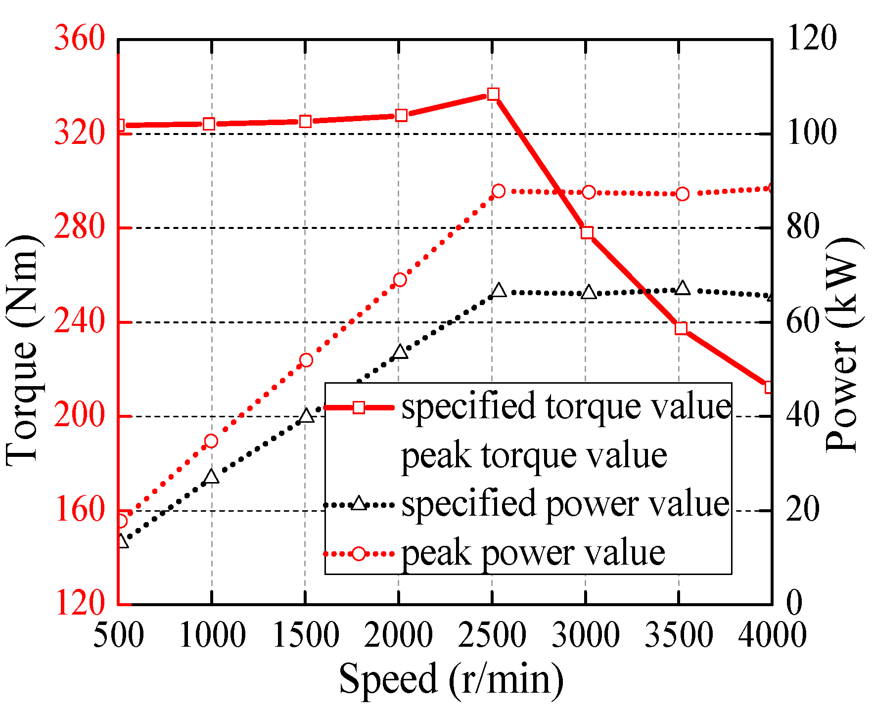
2.1. Vehicle Demand Power

For the RE-EV, the key to match the parameters of the power system components is to make the various APU parts work effectively together under the condition of satisfying the vehicle dynamic performance requirements.
Vehicle power demand on the power system can be expressed by Equation (1) [28]:
P r = ( m g f cos α + m g sin α + C D A 21.25 u 2 + δ m d u 3.6 d t ) u 3600 η T
where P r is the vehicle power demand; m is the vehicle mass; f is the coefficient of rolling friction; α is the road slope; C D is the air resistance coefficient; A is the frontal area; u is the velocity; δ is the rotational mass coefficient; η T is the power train efficient.
Based on a certain type of RE-EV bus, according to the vehicle specifications and performance requirements, a series of matching calculations and parts design of the APU system are carried out to satisfy the demand of vehicle bus range extended distance. The main parameters of electric bus, driving motor, and battery, are listed in Table 1. To satisfy the power requirement of the RE-EV bus, the engine selected is a 1.9 Liter four-stroke, turbocharged, intercooled high-speed diesel engine with an exhaust gas recirculation (EGR) system. The generator selected is a permanent magnet synchronous motor [29]. The specific parameters of the APU are shown in Table 2.

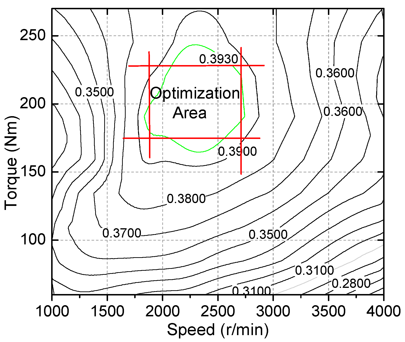
2.2. Engine Operating Characteristics

A mathematical model of the engine is built by the look-up table and interpolation method according to the engine performance test data. The fuel consumption rate defined in Equation (2) is expressed in an engine map, as shown in Figure 2. The power of the engine output can be expressed by Equation (3). The fuel consumption in the 220 g/(kWh) region circle is the fuel economy region of the engine. In this region, the engine speed is moderate, load is above average, fuel consumption is low, speed ranges from 1600 to 3000 r/min, torque ranges from 130 to 220 Nm, and the power output range is 25~70 kW.
b e = f ( n e , P e )
P e = T e 2 π n e 60 × 10 3
where b e is the engine fuel consumption rate (g/kWh); n e is the engine speed (r/min); T e is the engine torque (Nm); P e is the power of the engine output (kW).
Engine efficiency is a function of the engine speed and torque. This relationship is described by
η e = n e × T e P c = n e × T e M f H l = 3.6 × 10 6 b e H l
where P c is the enthalpy flow related to the fuel mass flow and M f ; H l stands for the lower heating value of the fuel.
The engine efficiency defined in Equation (4) is often expressed in an engine map, as shown in Figure 3. The “optimization area” labels the operating region with the highest efficiency [30]. The high-efficiency area represents the expected engine operation region. By constraining the engine torque and speed in such an area without degrading the engine output capacity, the engine shows high operation efficiency, which can help to improve fuel economy.

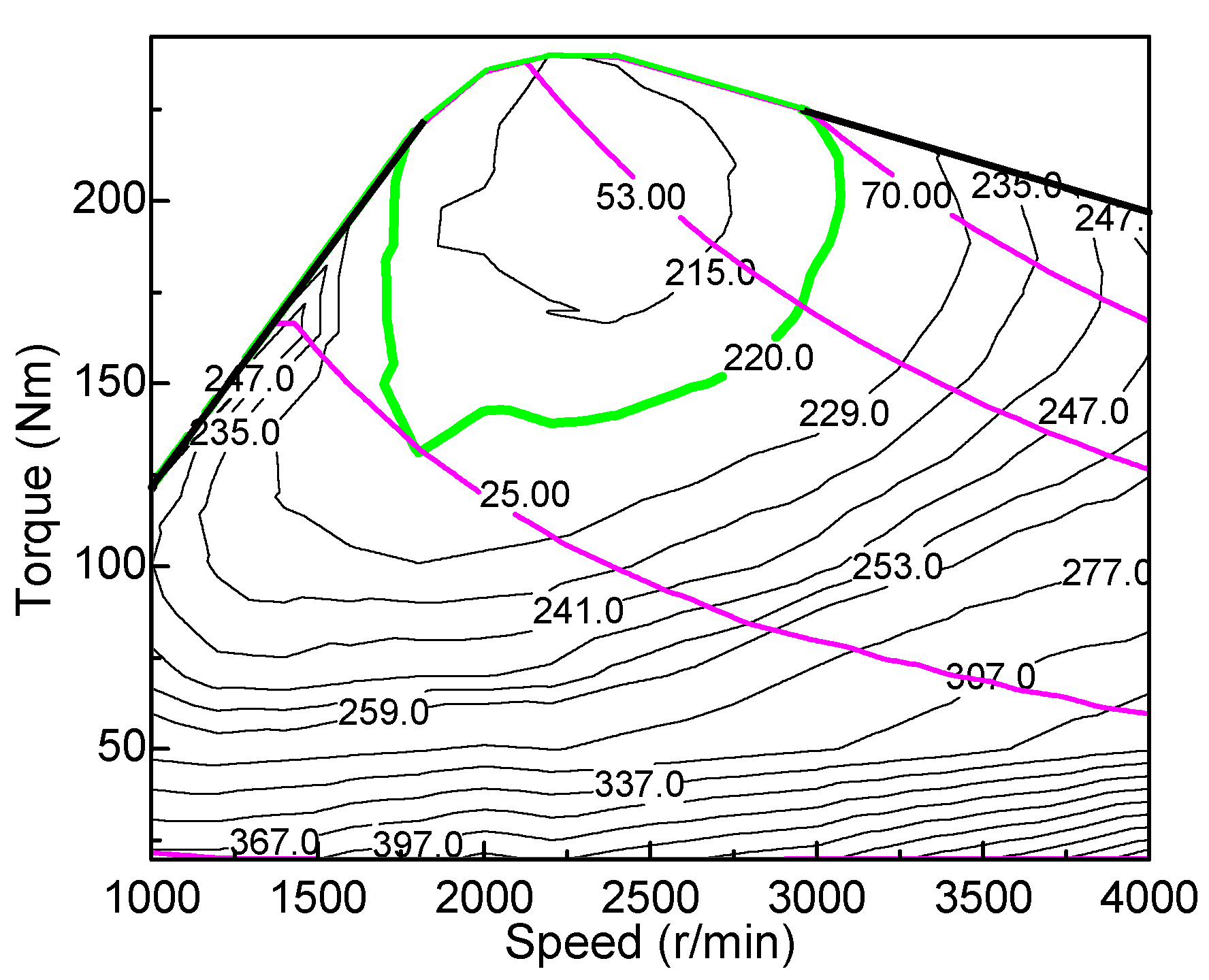
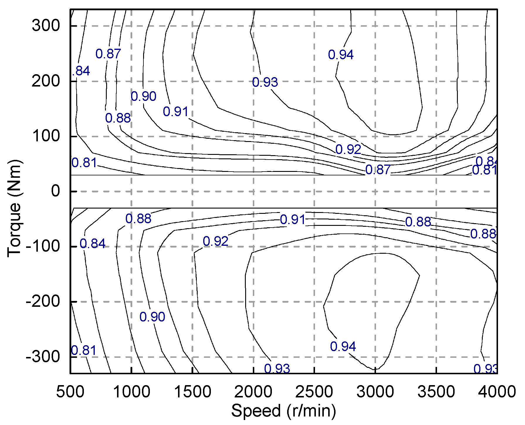
2.3. Generator Characteristics

Based on the performance curve of the generator and battery charging and discharging efficiency data, generator efficiency is defined as Equation (5):
η g e n = f ( n g , P g )
where η g e n is the generating efficiency of the generator; η g is the speed of the generator; P g is the output power of the generator.
The torque and power characteristics of the generator are shown in Figure 4. The generator efficiency map is shown in Figure 5. Comparison of the economy region is also shown in Figure 5. The generator can supply the engine load and keep the high efficiency region around 90%. Power and speed can be well-matched in the engine economy work region.

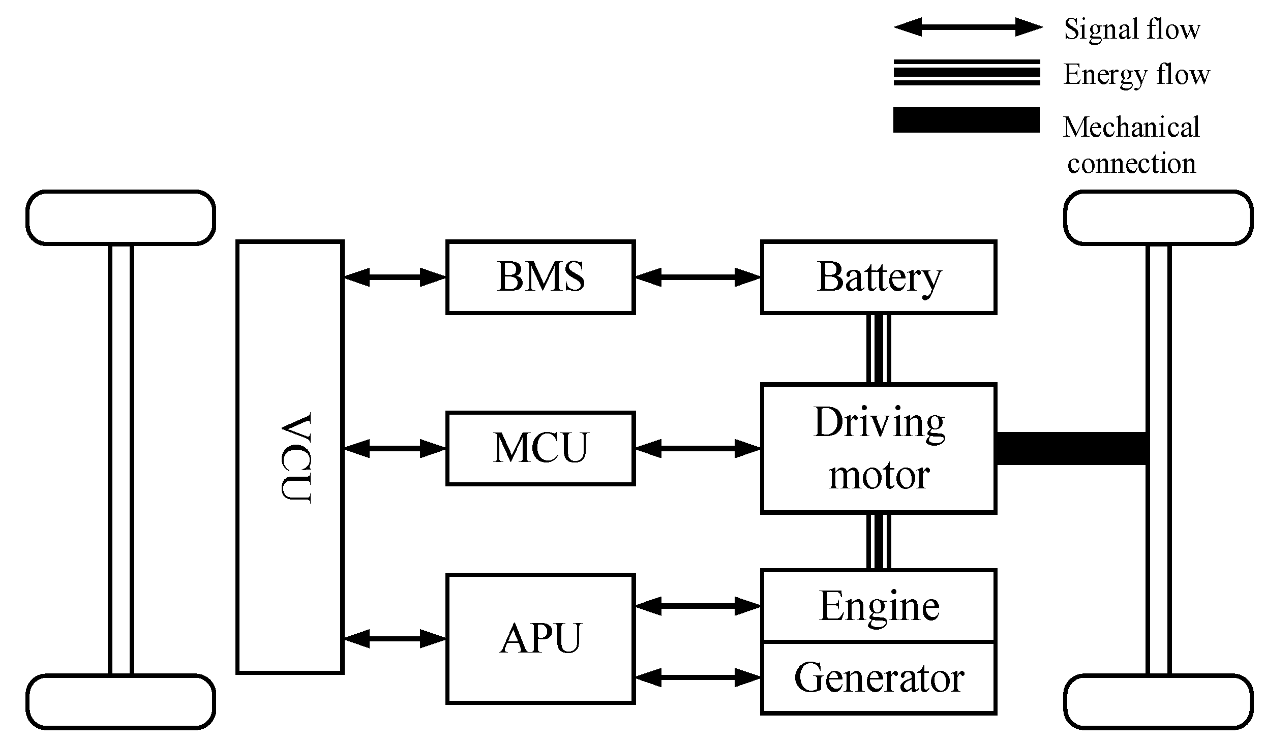
3. APU-Integrated Control System Design

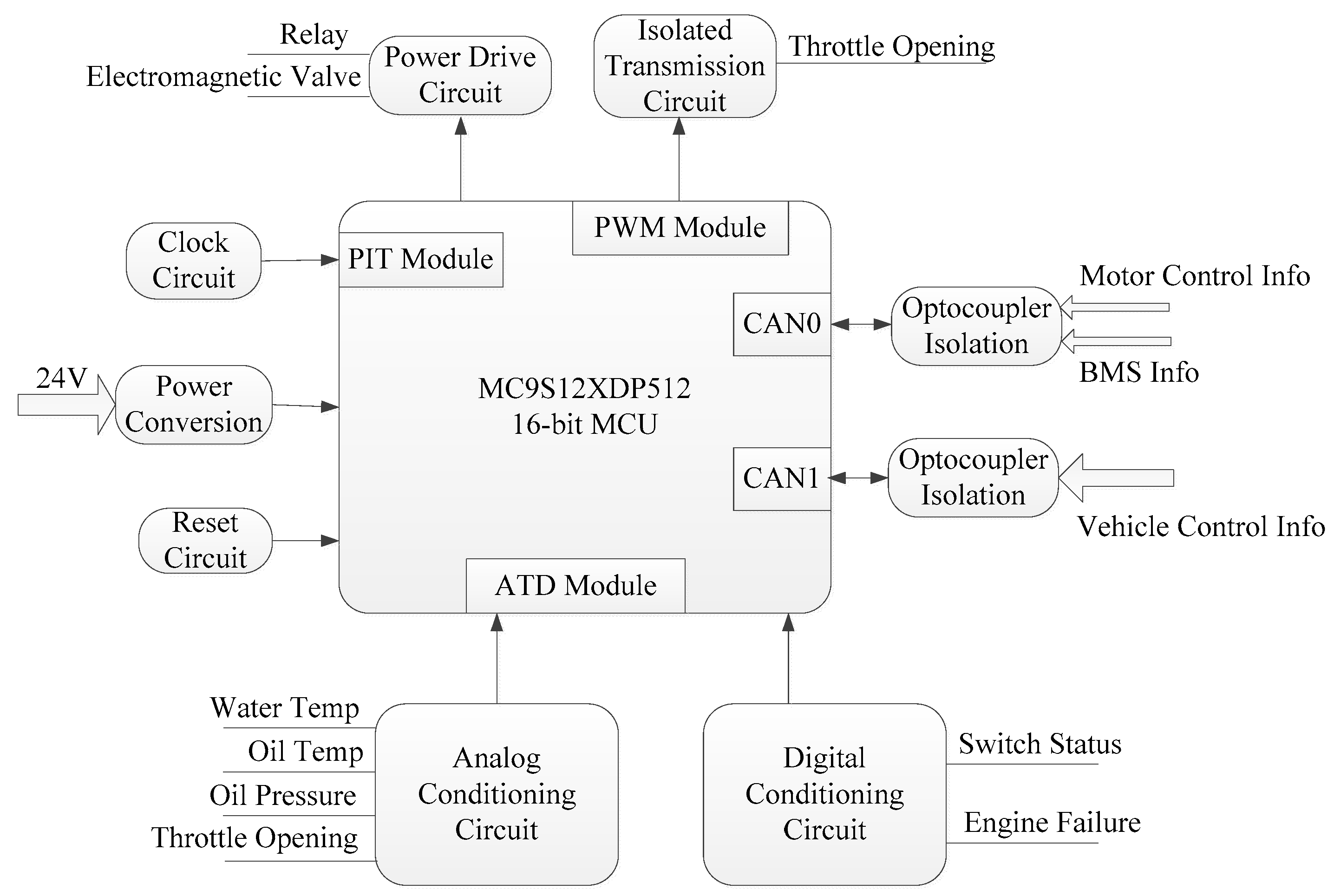
3.1. Hardware Design for the APU Controller

The APU controller is the core of the APU layer, controlling the working status of the APU system. The APU controller should have the following functions: obtain the sensor parameters; receive the start, stop, and power commands from the vehicle controller; achieve coordination control for the APU system; run the full diagnosis for the entire system. The hardware structure of the APU controller designed is shown in Figure 6.
The designed APU controller includes an input module, pulse-width modulation (PWM) output module, CAN communication module, and power output module. Analog inputs include a water temperature sensor, oil pressure sensor, engine speed sensor, and throttle position sensor. Digital signals include an engine diagnostic light alarm, on board diagnostic (OBD) alarm, oil water cut, and preheat indicator. The engine control unit (ECU) output throttle voltage signal is controlled by the PMW output modules. Battery, motor, and the control signal, communicate through CAN bus. The relay switches are controlled by the APU controller.

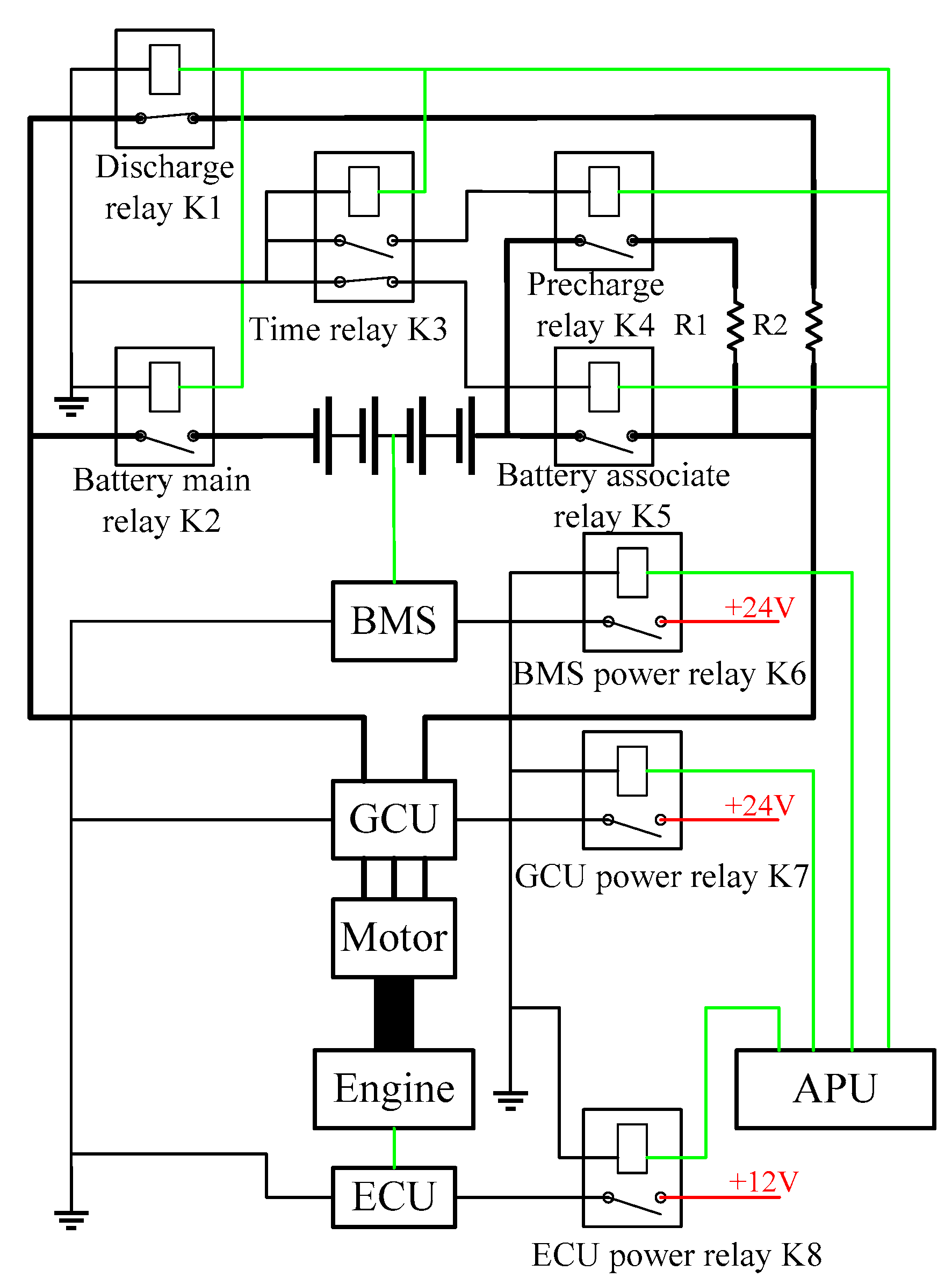
3.2. Circuit Design for the APU-Integrated Control System

The APU-integrated control system includes an ECU, generator control unit (GCU), Battery Management System (BMS), and APU controller. The system circuit designed is shown in Figure 7. The green line is the control signal line, while the black thin and thick lines represent the low and the high voltage circuits, respectively. The open relay switch means it is normally an open switch, while the closed relay switch means that it is normally a closed switch.
The APU-integrated control system circuit can be divided into two blocks: one for the controller power circuit and the other for the battery power circuit. The controller power circuit controls the relays K8, K7, and K6, to start the controller. The battery power circuit can be divided into three parts: the battery main circuit, pre-charge circuit, and discharge circuit. The battery main circuit is controlled by the relays K2 and K5. The pre-charge circuit is controlled by the relays K3, K4, and K5. The discharge circuit is controlled by the relay K1.

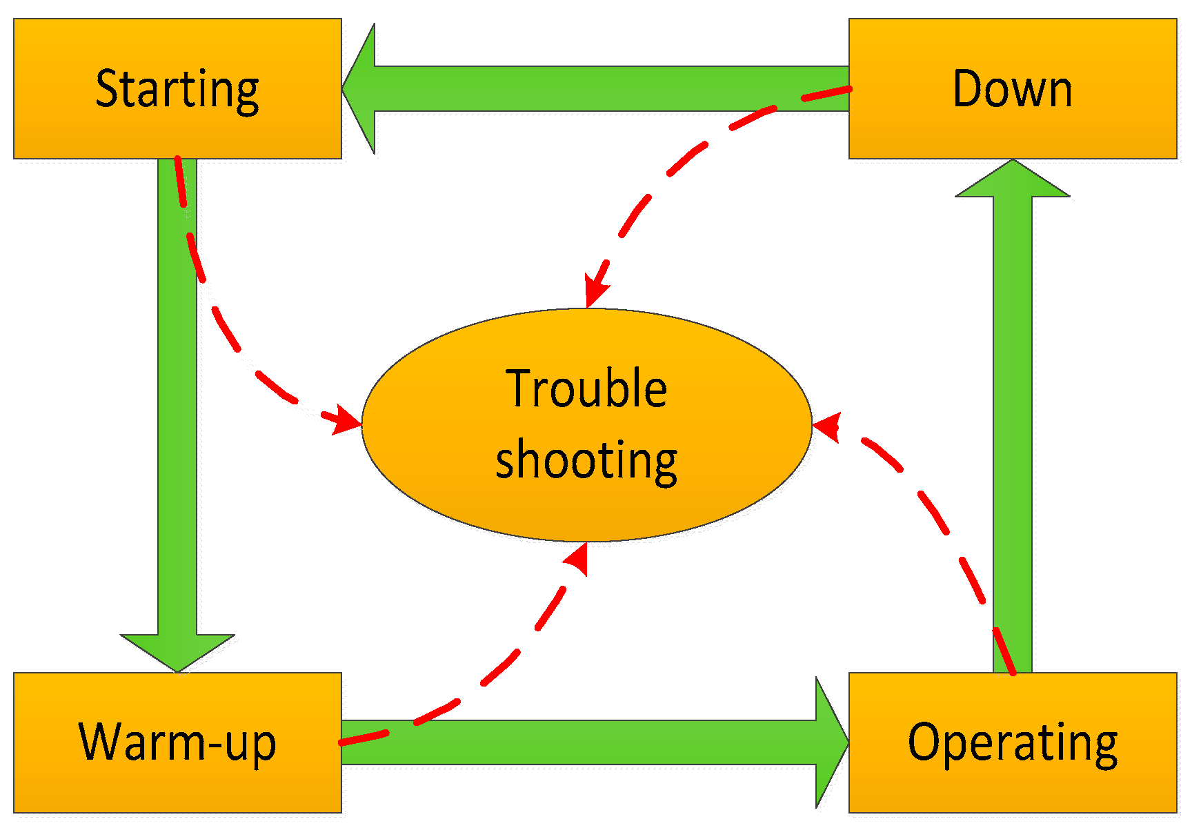
3.3. Software Design for the APU-Integrated Control System

The main function of the APU controller is to control the engine speed and generator torque, based on the requirements of vehicle power and battery SOC. The vehicle controller provides the target power to the APU according to the vehicle’s power and the battery SOC. The engine–generator coordination control uses the speed and torque dual-closed-loop control strategy, i.e., the closed-loop strategy for the speed of the engine and torque of the generator.
The software programs for APU include data acquisition, control strategy, data communication, and output feedback. The CodeWarrior software (Freescale Semiconductor, CodeWarrior5.0, Austin, TX, USA) integrated development environment is applied to complete the hardware driver and the APU control program coding. The coding of the hardware driver mainly includes the configuration of the bus and the initialization of the clock, analog to digital (ATD), PWM, and CAN modules. According to the working characteristics of the APU system, APU control logic is divided into five states: start, warm-up, operation, shut down, and trouble shooting. The control logic of the APU system is shown in Figure 8.

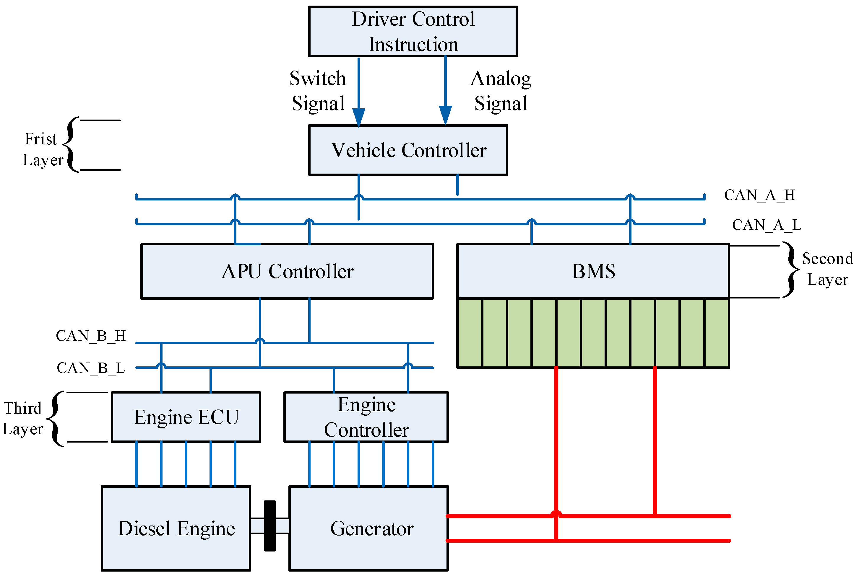
3.4. The Communication Solution for the Integrated Control System

As shown in Figure 9, according to the hierarchical control scheme, the vehicle control system can be divided into three layers.
The first layer is the controller of the vehicle, which receives operating instructions from drivers, as well as dynamic monitoring information from the APU and battery management systems. Then, it analyzes the driver’s intentions and calculates the vehicle power demand; completes the energy distribution between the power generating system and battery state according to the control strategy; and, lastly, sends the switch instructions and power demands to the APU.
The second layer includes the controller of the APU and battery management system. The controller of the APU receives the start or shutdown command from the controller of the vehicle, and controls the operation of the generating system accordingly. After receiving the power demand, it finds the most economical speed and torque by querying the map calibrated in advance, and then coordinates the engine and generator to realize the regulation of output power.
The third layer includes the ECU of the engine and controller of the generator. The ECU of the engine is mainly responsible for receiving and performing the switch instructions and throttle opening signal from the APU controller. The generator controller mainly accepts and executes instructions, such as electric switches or power generation modes and electromagnetic torque adjustments, from the controller of the APU system.
The design of the display interface is completed through the Labview virtual instrument software (National Instruments, Austin, TX, USA). The information in the display interface predominantly includes the basic-setting parameters of CAN communication, the message received, the message state judged, the message sent, data exported, and storage.

4. Strategy Design for the APU-Integrated Control System

In order to realize the vehicle power demand distributed between the battery and the APU, the APU controller needs to quickly and accurately control for output target power. The realization of target power needs to meet the engine and generator target speed and target torque requirements.

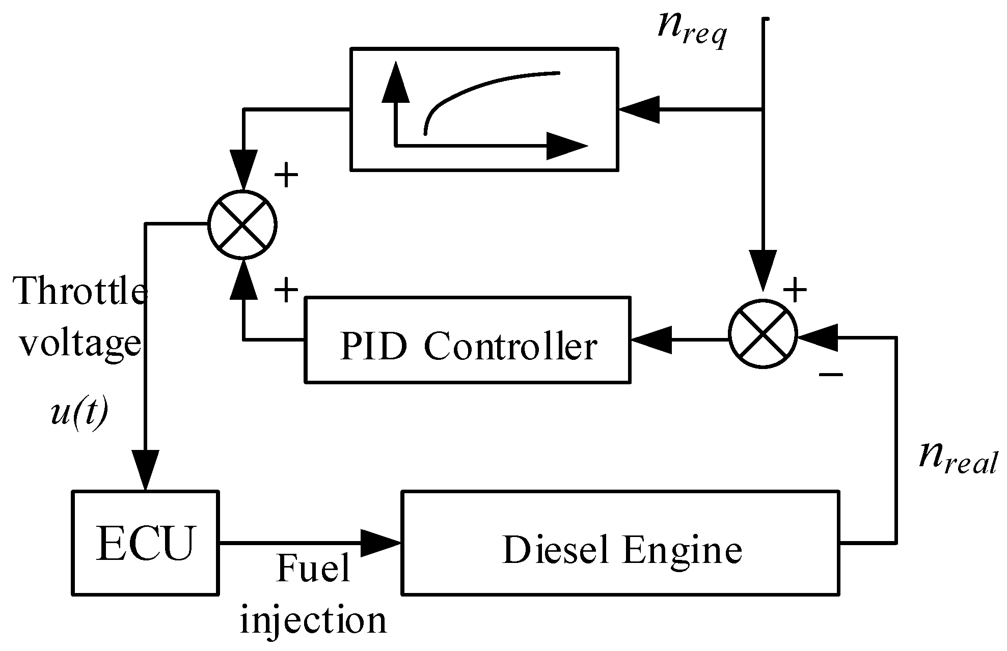
4.1. The Engine Speed Closed-Loop Control Method

Engine speed closed-loop control can use the incremental proportional–integral–derivative (PID) adjustment method. The input is the setting speed and the actual speed difference value, and the output is the engine throttle voltage value. Furthermore, by increasing the throttle feed forward control link, rapid and stable speed regulation can be achieved, as shown in Figure 10.
The throttle voltage u ( t ) in PID control with a feed forward link can be expressed as Equation (6):
u ( t ) = K P [ e ( t ) + 1 T I e ( t ) d t + T D d e ( t ) d t ] + u 0
where u ( t ) is the throttle voltage; K P is the proportional gain; T I the integral time; T D is the derivative time; e ( t ) is the difference between the engine target speed and the actual speed; u 0 is the test feed forward value.

4.2. The Generator Torque Control Method

The vector control technique is used to control the permanent magnet synchronous generator’s electromagnetic torque. By changing the coordinate of the space vector, the electromagnetic torque equation of the permanent magnet synchronous generator is established as Equation (7) [31]:
T g = 3 2 P n ( ψ d i q ψ q i d ) = 3 2 P n [ ψ f i q + ( L q L d ) i d i ]
where T g is the electromagnetic torque; P n is the pole pairs; ψ d , ψ q , ψ f are the d-and q-axis and the fundamental flux magnetic linkage; L d , L q are the d-and q-axis inductance; i d , i q are the d-and q-axis currents.

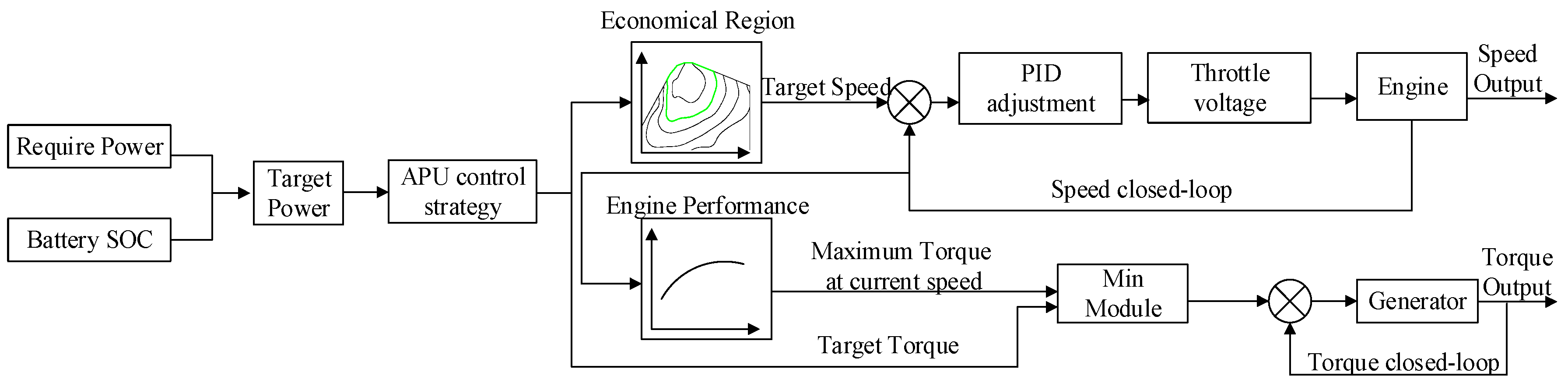
4.3. Engine–Generator Coordination Control Strategy

According to the battery system SOC design requirements, when the vehicle controller is given a power generation system power instruction, the APU system controller can control the system speed and torque reasonably. In order to stabilize the engine at the most economical point of the corresponding power, for each output power, the optimum rotational speed and corresponding torque value in the most economical region of the engine, are calculated, so as to obtain the corresponding throttle position of the engine and the output current of the generator.
The engine–generator coordination control uses the speed and torque dual-closed-loop control strategy, i.e., the closed-loop strategy for the speed of the engine and torque of the generator, as shown in Figure 11.
According to the target power, the APU controller calculates the engine target rotation speed, and controls the engine throttle opening through the APU controller PID control module, thereby controlling the engine speed in a closed loop. The output torque of the generator is determined by the engine output current, and the target current is determined by the target power and the bus voltage. The generator controller performs current closed loop control and outputs current according to the target current.

5. Experimental Research on the APU Test Bench

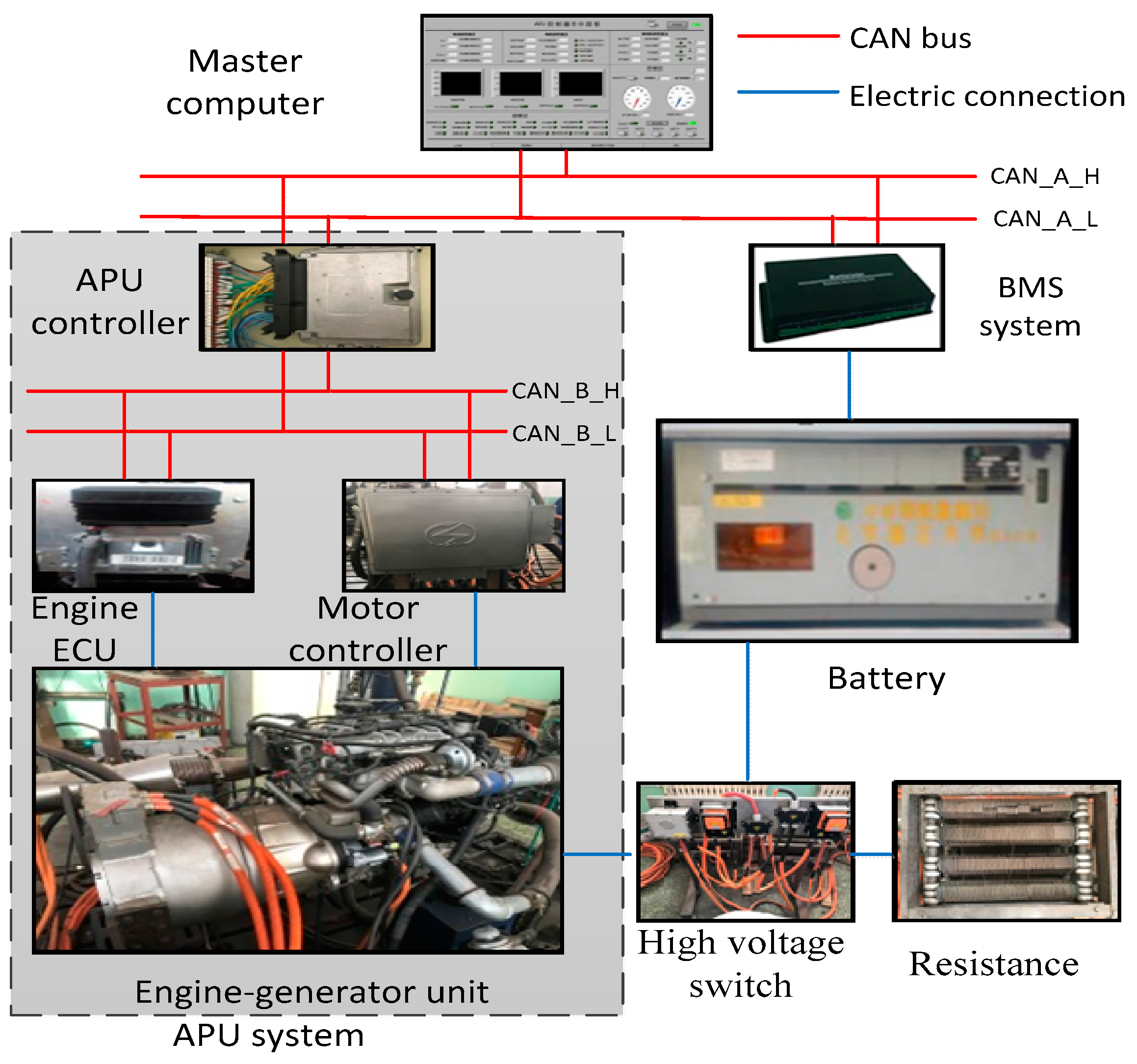
5.1. The APU Test Bench

The APU test bench includes the computer data display part, the control part, and the bench with its accessories. Each part is an independent system. The controller in the system establishes a communication connection through CAN bus. A physical connection is constructed between the battery and generator, and resistance is achieved by a high voltage cable, as shown in Figure 12. To realize whether parts coordination works, the APU controller outputs a corresponding signal to the ECU and motor controller, and the control strategy and control logic of the APU power system is verified in a bench test.

5.2. APU Test Application

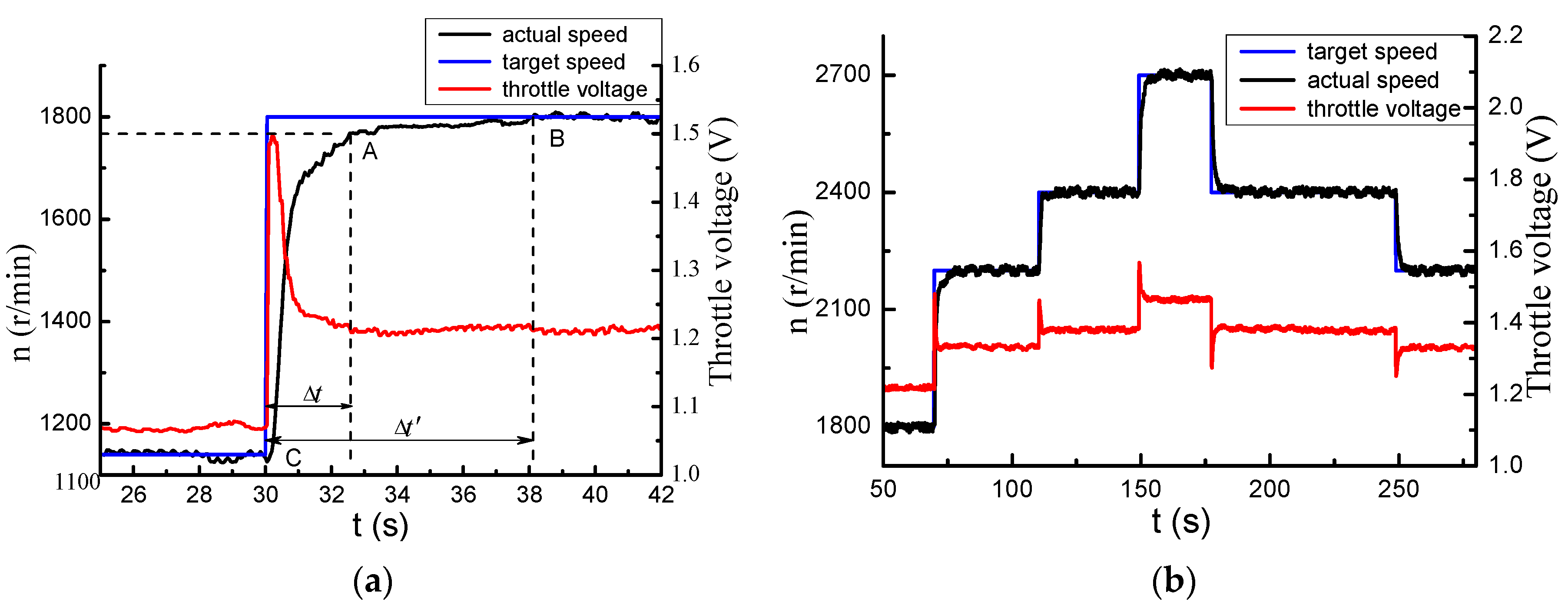
5.2.1. Engine Speed Control Test

The incremental PID control algorithm is used to achieve APU system speed control. In order to verify the control effect of the APU system, the speed step test and disturbance stability test are carried out.
Figure 13 shows the speed step response under PID control. It is generally considered that the system can reach the target speed value within 30 r/min when it is close to the target speed. As shown in Figure 13a, the system has a fast response speed, good tracking, and has no overshoot phenomenon as shown in Figure 13b. When the speed is in a wide range of switching process, the actual speed can follow the target speed changes well.
During the test, the stability of the speed control was checked by sending a torque command to the generator to simulate the disturbance in the working environment. As shown in Figure 14, the test results show that the system stability is good.

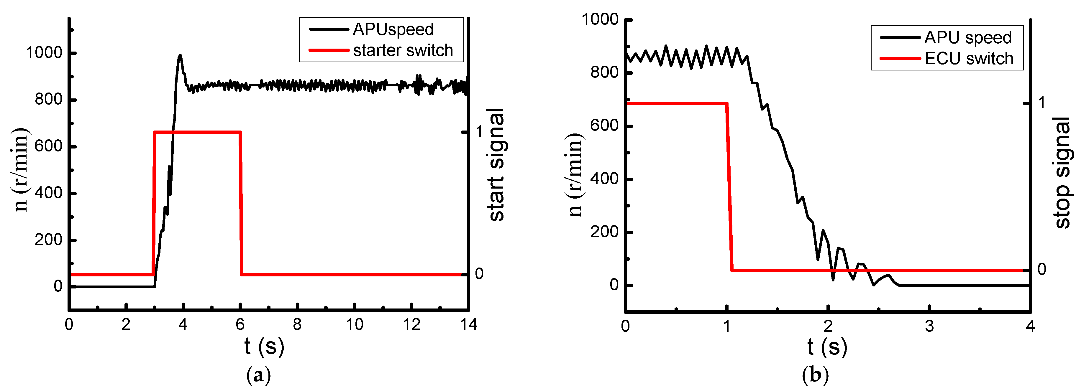
5.2.2. Start-Stop Test
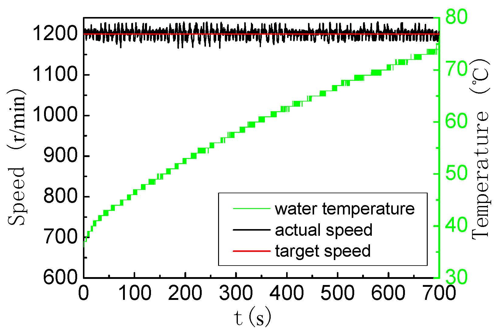
The APU system start and stop control is achieved through the corresponding relay switches, which are driven by the APU controller. Figure 15 shows the speed change of the APU system during start-up and shut down.

5.2.3. Warm-Up Test

The APU system should enter the warm-up working condition after starting. The selected engine speed of 1200 r/min and the water temperature rising curve are shown in Figure 16. The water temperature increases to a certain value, then the conventional working mode is changed in order to avoid mechanical damage caused by the lower water temperature, as shown in Figure 17.

5.2.4. Charging Test

After reaching a normal operating temperature, the APU system runs directly into the corresponding work point according to the current power command. The charging object of the APU system is the battery in the test.
After the system completes the warm-up, the control system will control the APU system to operate at a certain operating point. The data changes during this process are shown in Figure 18.
As shown in Figure 18a, the engine speed will fluctuate in the process of increasing torque. Although the engine speed can quickly restore to the target speed under PID control, the current and APU power will also fluctuate in the process of engine adjustment, as shown in Figure 18b,c.
In the APU control system, generator torque control is based on control of the current and the response is very fast. The engine speed can be regarded as the function of the throttle opening and the load, so the speed control adjustment is relatively slow. The rapid change of the target power will cause frequent fluctuations in the engine speed between different power levels, and different response speeds will cause an overshoot in speed control, which will cause the efficiency of the generator to reach 100% in some points. As shown in Figure 18d, the efficiency of the generator is ineffective at these points.

5.3. APU Power Following the Experiment

In the asynchronous regulation strategy, APU control can be decomposed into speed regulation and torque regulation. In the speed regulation, the speed needs to quickly and accurately respond to the target speed, and in the torque regulation, the speed is required to stay near the target speed under the torque disturbance.

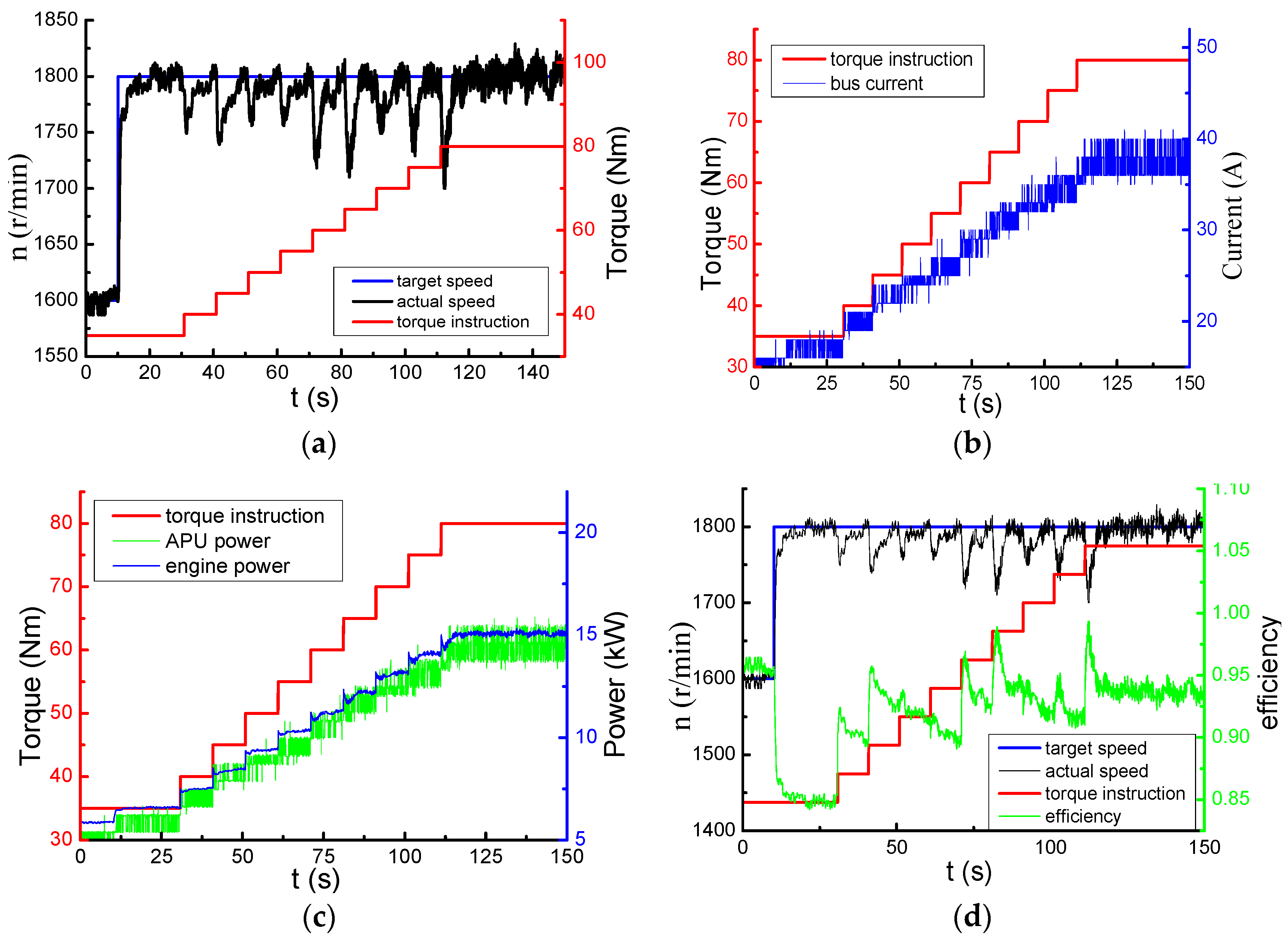
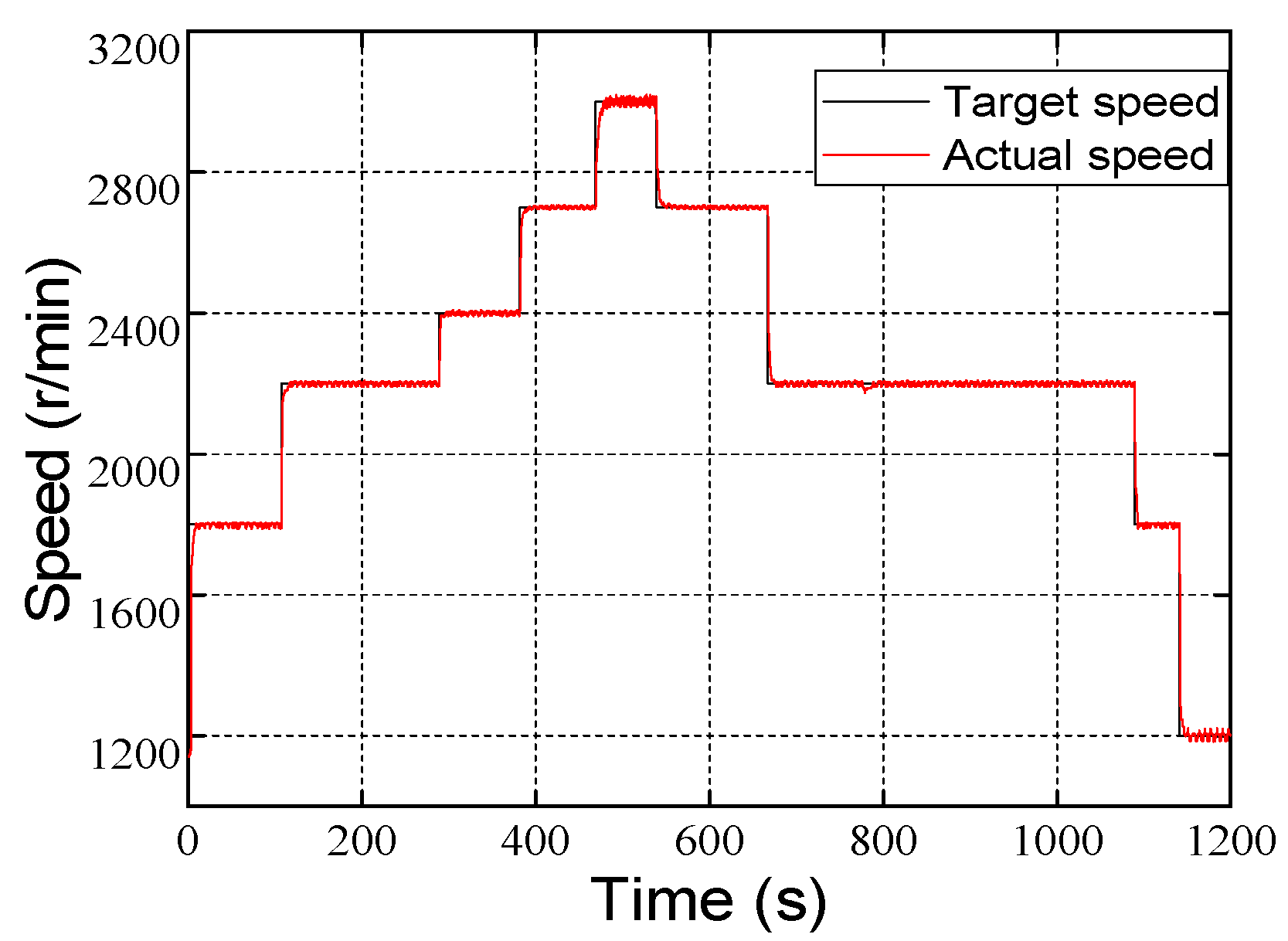
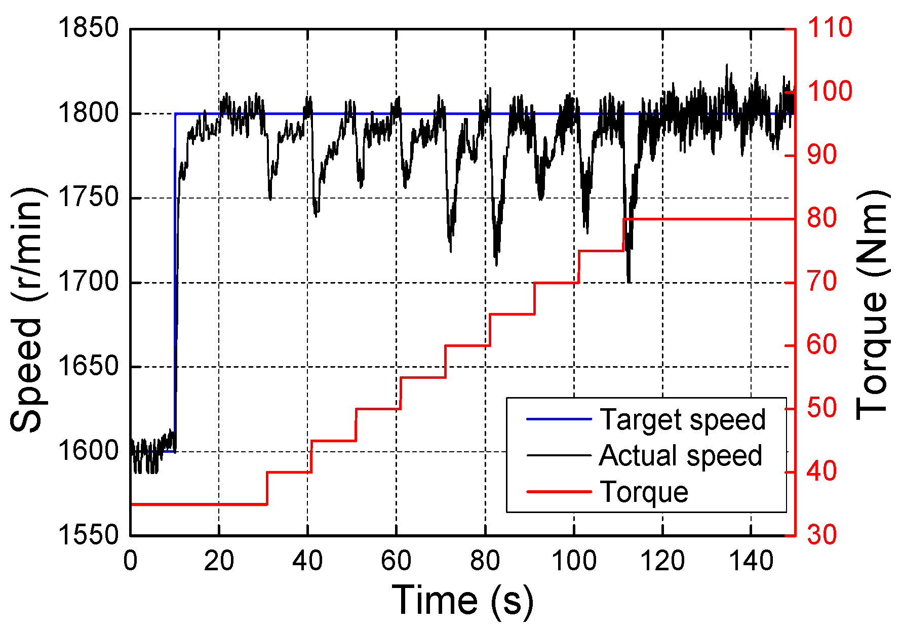
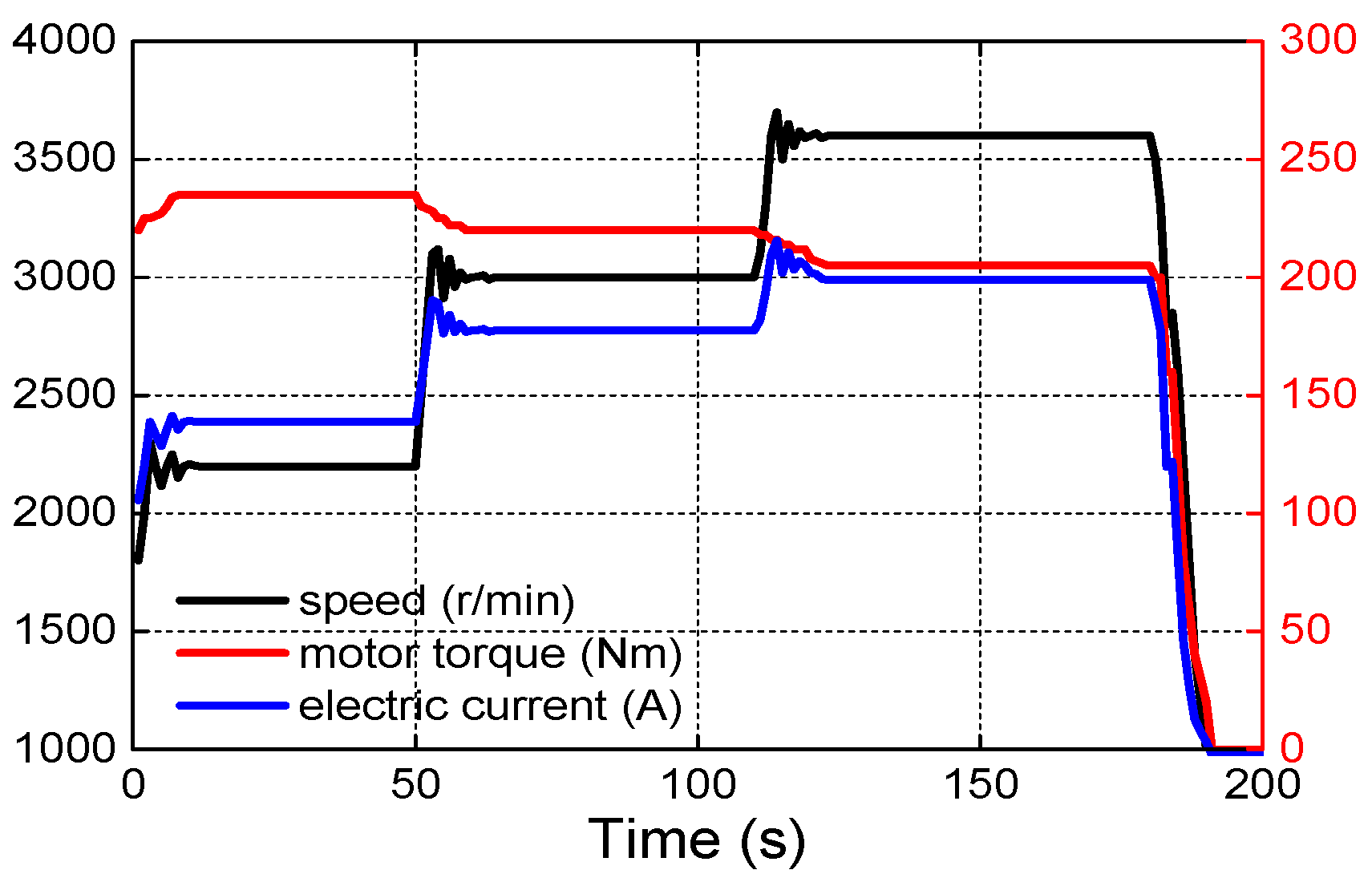
5.3.1. Speed Regulation Experiment

As shown in Figure 19, under the current PI control, engine speed can follow the acceleration and deceleration steps of the target speed. When the speed has a large-scale switch, the engine speed is also able to follow the target speed well.

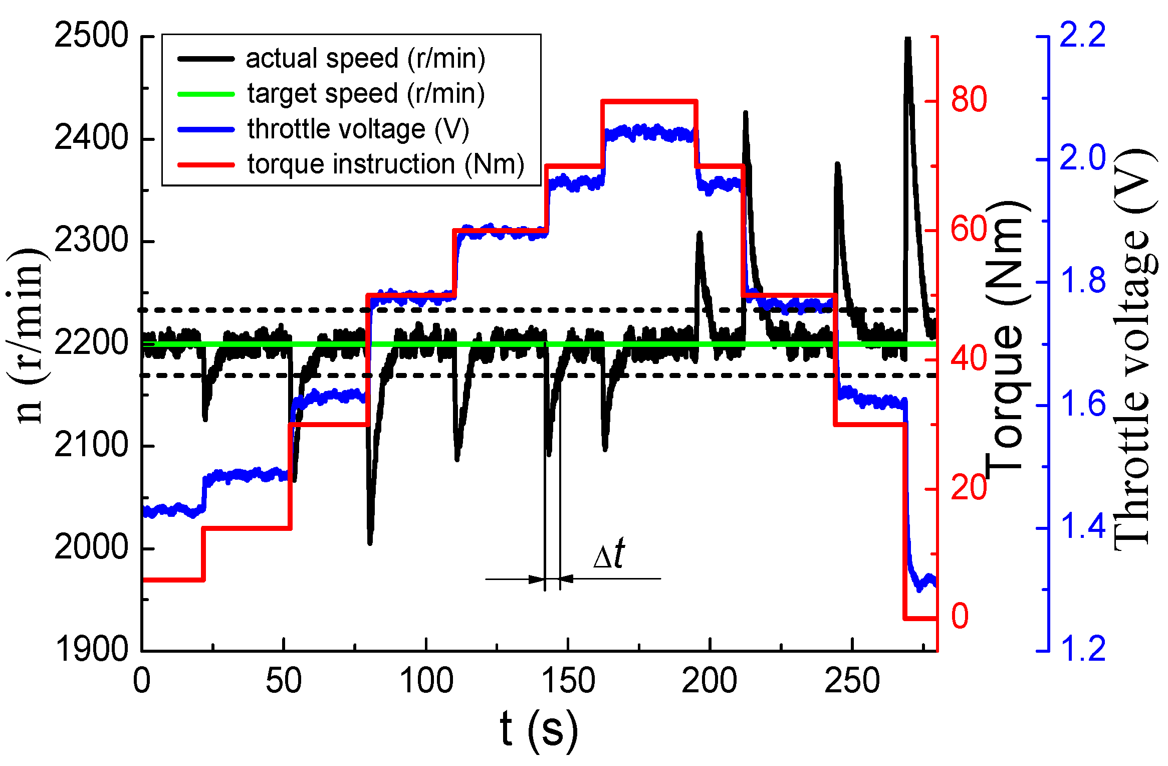
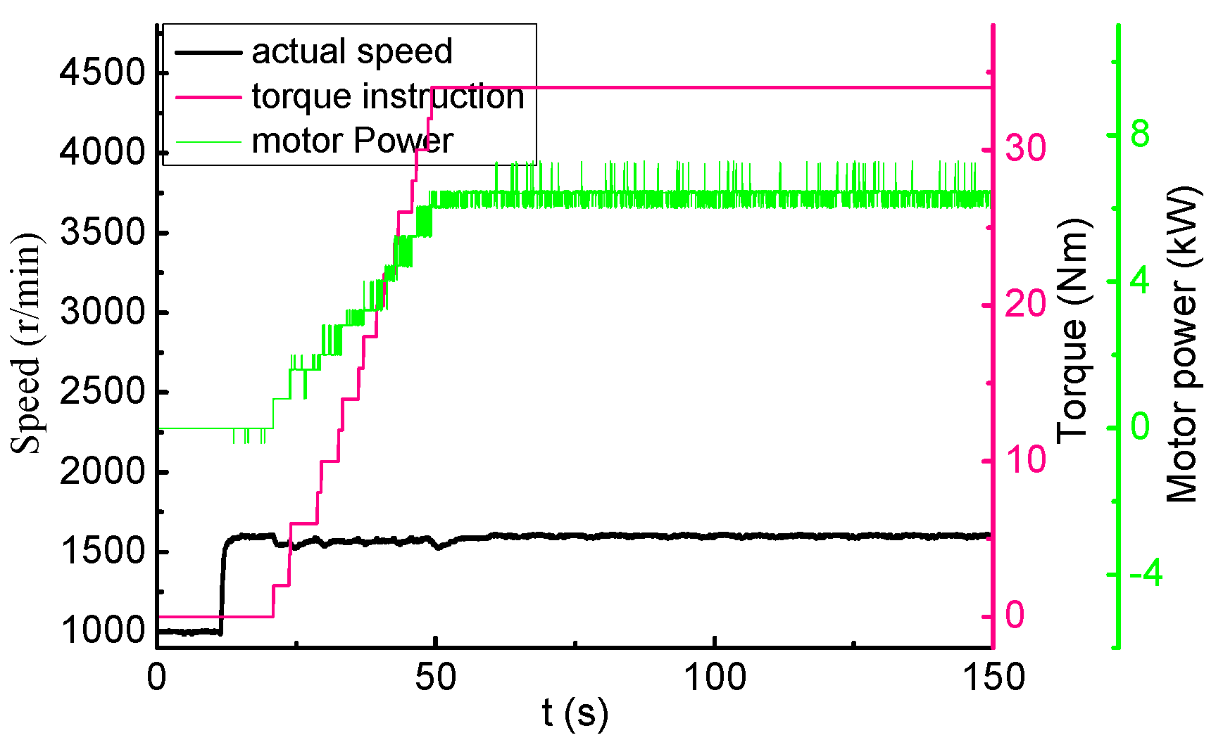
5.3.2. Torque Regulation Experiment

As shown in Figure 20, the engine speed will fluctuate in the process of increasing torque. Although the engine speed can quickly restore to the target speed under PID control, the torque should not increase too fast.

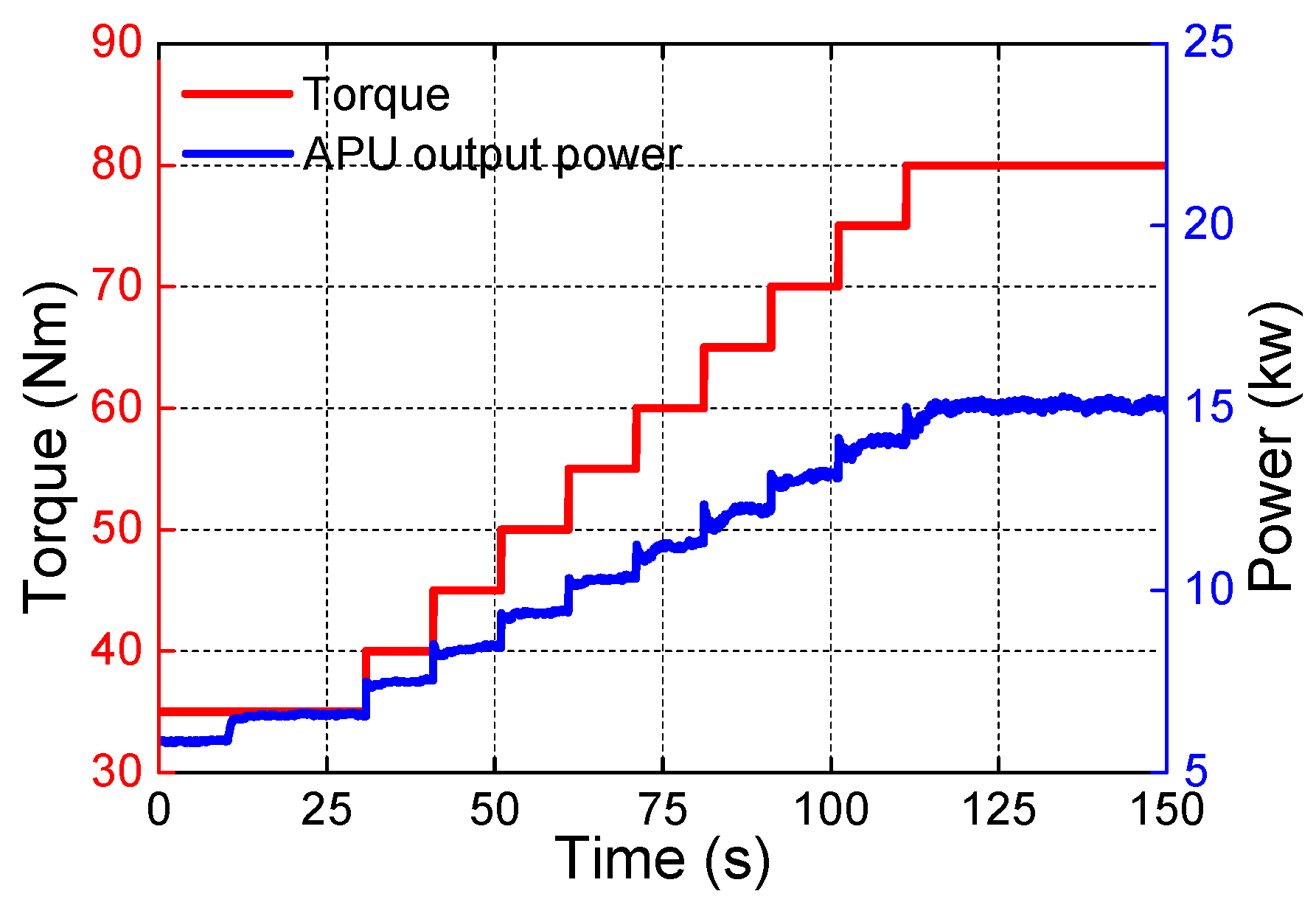
5.3.3. Power Regulation Experiment

When the APU output power undergoes small-scale changes, power can be followed by changing the torque while remaining at the same engine speed. As shown in Figure 21, the change of APU output power can be followed by the changing of the torque.
When the APU system is adjusted by 2000 r/min, 3000 r/min, and 3500 r/min respectively, adjusting the torque of the generator output gives the corresponding optimal economy-power. It can be seen from Figure 22 that the system can realize specified power output generally and stabilize transition between different speeds.
When adjusting the speed and torque of the engine, the engine–generator synchronous dynamic regulation strategy is used, as shown in Figure 22, while adjusting the speed and slowly reducing the torque, so as to achieve the target power. The slope of the torque is calibrated by the experiments.
The output power and fuel economy under different speeds is shown in Table 3, where it can be seen that the optimal economy of the engine is observed at 2200 r/min. In order to improve the power performance of the vehicle, the output power of the APU system can also be improved appropriately. The economy of the system declined, but still meets the economic requirements.

6. Conclusions

The integrated system design and test technique of the APU for a RE-EV were studied in this paper. The APU test bench includes the computer data display part, the control part, and the bench with the engine, generator and battery system. The full test data of APU control and performance effects was verified by test application. The results and conclusions can be summarized as follows:
(1)
A new integrated system was built that used APU parts, in the electrical vehicle work state, and fulfilled the performance requirements. The optimization algorithm of the APU parameters, based on the characteristics of the efficiency maps of the engine and the generator, was analyzed and developed.
(2)
An APU controller was designed to combine the hardware, software, and communication system design, which considered the optimization coordination control strategy for engine speed and generator torque.
(3)
The comprehensive test bench of the APU system was constructed, which can receive instructions from electric vehicles and feedback from the battery SOC. The controller of the designed APU system can deal with the engine acquisition and generator data, communicate with the battery system, and automatically control APU work at a reasonable speed and torque according to the power demand of the vehicle. All input and output parameters and the control processing can be displayed in real time on a computer.
(4)
The engine speed control and integrated control experiment of the APU system were completed on the test bench. The power regulation experiment results for the optimization of design parameters were obtained. The test results showed that the test control system and the relevant control logic are reliable. The APU-integrated system can operate with high economic efficiency and fulfil the RE-EV vehicle performance requirements.

Acknowledgments

The authors wish to acknowledge the Natural Science Foundation of China (NSFC) for their financial support (project number 51375048) and give thanks to Jie Bao and Zhiqiang Zhang for their help in the process of constructing the APU test bench and APU test.

Author Contributions

Hong Zhang conceived and designed this study; Hong Zhang designed this integrated system and matched parameters of APU parts; Zhuang Xing designed software and hardware of APU controller; Hong Zhang and Zhuang Xing designed the communication system; Hong Zhang, Zhuang Xing, Jiajian Song and Qiangqiang Yang constructed the test bench; Zhuang Xing, Jiajian Song and Qiangqiang Yang analyzed experiments data; Hong Zhang and Zhuang Xing wrote the paper.

Conflicts of Interest

The authors declare no conflict of interest.

Nomenclature

P r Vehicle demand power
m Vehicle mass
f Rolling resistance coefficient
α Road gradient
C D Air resistance coefficient
A Frontal area
u Driving speed
δ Vehicle rotational mass conversion factor
η T Mechanical transmission efficiency
b e Fuel consumption rate
n e Engine speed
P e Power of the engine output
T e Engine torque
η e Engine efficiency
P c Enthalpy flow
M f Fuel mass flow
H l Fuel’s lower hearting value
η g e n Efficiency of the generator
n g Speed of the generator
P g Output power of the generator
u ( t ) Throttle voltage
K P Proportional gain
T I Integral time
T D Derivative time
e ( t ) Difference
u 0 Test feed forward value
T g Electromagnetic torque
P n Pole pairs
ψ d , ψ q The d- and q-axis magnetic linkage
ψ f Fundamental flux magnetic linkage
L d , L q The d- and q-axis inductance
i d , i q The d- and q-axis currents

References

  1. Markle, T. Plug-in HEV Vehicle Design Options and Expectations, ZEV Technology Symposium; National Renewable Energy Laboratory: Golden, CO, USA, 2006; pp. 36–41. [Google Scholar]
  2. Al-Alawi, B.M.; Bradley, T.H. Total Cost of Ownership, Payback, and Consumer Preference Modeling of Plug-in Hybrid Electric Vehicles. Appl. Energy 2013, 103, 488–506. [Google Scholar] [CrossRef]
  3. Wolschendorf, J.; Rzemien, K.; Gian, D. Development of Electric and Rang-Extended Electric Vehicles through Collaboration Partnerships. SAE Int. J. Passeng. Cars Electron. Electr. Syst. 2010, 3, 215–219. [Google Scholar] [CrossRef]
  4. Jalil, N.; Kheir, N.A.; Salman, M. A Rule-based Management Stratagy for a Series Hybrid Vehicle. In Proceedings of the American Control Conference, Albuquerque, NM, USA, 6 June 1997; pp. 689–693. [Google Scholar]
  5. Song, Z.; Hofmann, H.; Li, J.; Hou, J.; Han, X.; Ouyang, M. Energy Management Strategies Comparison for Electric Vehicles with Hybrid Energy Storage System. Appl. Energy 2014, 134, 321–331. [Google Scholar] [CrossRef]
  6. Chen, Z.; Xia, B.; You, C.; Mi, C. A Novel Energy Management Method for Series Plug-in Hybrid Electric Vehicles. Appl. Energy 2015, 145, 172–179. [Google Scholar] [CrossRef]
  7. Du, J.; Chen, J.; Gao, M.; Wang, J. Energy Efficiency Oriented Design Method of Power Management Strategy for Range-Extended Electric Vehicles. Math. Probl. Eng. 2016, 2016, 9203081. [Google Scholar] [CrossRef]
  8. Abdelgadir, A.A.; Alsawalhi, J.Y. Energy Management Optimization for an Extended Range Electric Vehicle. In Proceedings of the 2017 7th International Conference on Modeling, Simulation and Applied Optimization (ICMSAO), Sharjah, UAE, 4–6 April 2017. [Google Scholar]
  9. Li, J.; Jin, X.; Xiong, R. Multi-objective Optimization Study of Energy Management Strategy and Economic Analysis for A Range-extended Electric Bus. Appl. Energy 2017, 194, 798–807. [Google Scholar] [CrossRef]
  10. Xiong, R.; Zhang, Y.; He, H.; Zhou, X.; Pecht, M. A Double-scale, Particle-filtering, Energy State Prediction Algorithm for Lithium-ion Batteries. IEEE Trans. Ind. Electron. 2017, 65, 1526–1538. [Google Scholar] [CrossRef]
  11. Xiong, R.; Tian, J.; Mu, H.; Wang, C. A Systematic Model-based Degradation Behavior Recognition and Health Monitor Method of Lithium-ion Batteries. Appl. Energy 2017, 207, 367–378. [Google Scholar] [CrossRef]
  12. Xiong, R.; Cao, J.; Yu, Q.; He, H.; Sun, F. Critical Review on the Battery State of Charge Estimation Methods for Electric Vehicles. IEEE Access 2017, PP, 1. [Google Scholar] [CrossRef]
  13. Chen, B.; Wu, Y.; Tsai, H. Design and Analysis of Power Management Strategy for Range Extended Electric Vehicle Using Dynamic Programming. Appl. Energy 2014, 113, 1764–1774. [Google Scholar] [CrossRef]
  14. Zhang, S.; Xiong, R.; Sun, F. Model Predictive Control for Power Management in a Plug-In Hybrid Electric Vehicle with a Hybrid Energy Storage System. Appl. Energy 2017, 185, 1654–1662. [Google Scholar] [CrossRef]
  15. Skugor, B.; Deur, J. Instantaneous Optimization-Based Energy Management Control Strategy for Extended Range Electric Vehicle; SAE Technical Paper; SAE 2013 World Congress & Exhibition: Detroit, MI, USA, 2013. [Google Scholar]
  16. Chen, C.; Xiong, R.; Shen, W. A Lithium-ion Battery-in-the-loop Approach to Test and Validate Multi-scale Dual H Infinity Filters for State of Charge and Capacity Estimation. IEEE Trans. Power Electron. 2018, 33, 332–342. [Google Scholar] [CrossRef]
  17. Du, J.; Chen, J.; Song, Z.; Gao, M.; Ouyang, M. Design Method of a Power Management Strategy for Variable Battery Capacities Range-extended Electric Vehicles to Improve Energy Efficiency and Cost-effectiveness. Energy 2017, 121, 32–42. [Google Scholar] [CrossRef]
  18. Xiong, R.; Yu, Q.; Wang, L.; Lin, C. A Novel Method to Obtain the Open Circuit Voltage for the State of Charge of Lithium Ion Batteries in Electric Vehicles by Using H Infinity Filter. Appl. Energy 2017, 207, 341–348. [Google Scholar] [CrossRef]
  19. Xiong, R.; Cao, J.; Yu, Q. Reinforcement Learning-based Real-time Power Management for Hybrid Energy Storage System in the Plug-in Hybrid Electric Vehicle. Appl. Energy 2018, 211, 538–548. [Google Scholar] [CrossRef]
  20. Rodrigues, M.; King, S.; Scott, D.; Wang, D. Advanced Energy Management Strategies for Range Extended Electric Vehicle; SAE Technical Paper; Tata Motors European Technical Centre: West Midlands, UK, 2015. [Google Scholar]
  21. Liu, G.; Zhang, J. Efficiency Optimization and Control of Auxiliary Power Unit for Extended Range Electric Vehicles. In Proceedings of the 2nd International Conference on Mechanical, Electronic and Information Technology Engineering (ICMITE 2016), Chongqing, China, 21–22 May 2016. [Google Scholar]
  22. Chen, L.; Wang, X.; Huang, X.; Gan, P.; Cheng, W. Modeling and Simulation of the Auxiliary Power System in Extended Range Electric Vehicle. Appl. Mech. Mater. 2013, 397–400, 1858–1862. [Google Scholar] [CrossRef]
  23. Lin, J.; Gu, J.; Yu, X. Study on SHEV Generator Grup Control Strategy Based on Fuzzy Theory. China Mech. Eng. 2013, 24, 1983–1987. [Google Scholar]
  24. He, B.; Yang, M. Robust LPV Control of Diesel Auxiliary Power Unit for Series Hybrid Electric Vehicles. IEEE Trans. Power Electron. 2006, 21, 791–798. [Google Scholar]
  25. Wang, D.; Xue, C.; Song, S.X. Parameter Matching and Performance Simulation for a Distributed Power Extended-Range Electric Vehicle. Appl. Mech. Mater. 2014, 496–500, 1360–1364. [Google Scholar] [CrossRef]
  26. Wu, D.; Lu, T.; Zhang, L.; Gong, X. Parameter Matching and Simulation Study of Powertrain for Extended-Range Electric Vehicle. Adv. Mater. Res. 2014, 926–930, 1387–1391. [Google Scholar] [CrossRef]
  27. Fiengo, G.; Glielmo, L.; Vasca, F. Control of Auxiliary Power Unit for Hybrid Electric Vehicles. IEEE Trans. Control Syst. Technol. 2007, 15, 1122–1130. [Google Scholar] [CrossRef]
  28. Jiang, Y.; Zhou, H.; Lin, C.; Wang, L. A Study on Energy Management Control Strategy for an Extended-Range Electric Vehicle. In Proceedings of the International Conference on Energy and Mechanical Engineering (EME2015), Wuhan, China, 17–18 October 2015. [Google Scholar]
  29. Zhang, H.; He, Z.; Wang, Y. Control Strategy Research of Auxiliary Power Unit in Range-Extended Electric Bus. In Proceedings of the 2014 IEEE Transportation Electrification Conference and Expo Asia-Pacific, Beijing, China, 31 August–3 September 2014. [Google Scholar]
  30. Zhang, X.; Mi, C. Vehicle Power Management: Modeling, Control and Optimization; Springer: London, UK, 2011. [Google Scholar]
  31. Tang, T. Research on Permanent Magnet Synchronous Generator Sensorless Vector Control System. Master’s Thesis, Beijing Jiaotong University, Beijing, China, 2008; pp. 28–30. [Google Scholar]
Figure 1. Auxiliary power unit (APU) power system. BMS: Battery Management System; MCU: Motor Control Unit.
Energies 11 00187 g001
Figure 2. Engine fuel consumption contour map.
Energies 11 00187 g002
Figure 3. Engine efficiency map.
Energies 11 00187 g003
Figure 4. Full load torque and power characteristics of the generator.
Energies 11 00187 g004
Figure 5. Generator efficiency map.
Energies 11 00187 g005
Figure 6. APU controller hardware schematic.
Energies 11 00187 g006
Figure 7. The system circuit.
Energies 11 00187 g007
Figure 8. The control logic of the APU system.
Energies 11 00187 g008
Figure 9. Schematic diagram of hierarchical control.
Energies 11 00187 g009
Figure 10. Engine speed feed forward and feedback proportional–integral–derivative (PID) control.
Energies 11 00187 g010
Figure 11. APU system control schematic.
Energies 11 00187 g011
Figure 12. APU test bench structure.
Energies 11 00187 g012
Figure 13. Engine speed step response curve under no-load: (a) Fast response speed; (b) Follow the target speed changes well.
Energies 11 00187 g013
Figure 14. Disturbance stability test results.
Energies 11 00187 g014
Figure 15. APU start-stop test results. (a) APU system start-up process; (b) APU system shut down process.
Energies 11 00187 g015
Figure 16. Water temperature rising curve.
Energies 11 00187 g016
Figure 17. Warm-up test process.
Energies 11 00187 g017
Figure 18. Control process from warm-up to operating point. (a) Speed control; (b) Charging current; (c) Power change; (d) Efficiency of the generator.
Energies 11 00187 g018
Figure 19. APU speed step response curve.
Energies 11 00187 g019
Figure 20. APU torque regulation curve.
Energies 11 00187 g020
Figure 21. APU power regulation curve.
Energies 11 00187 g021
Figure 22. Test of power generation with the power generation system.
Energies 11 00187 g022
Table 1. Range-extended electric vehicle (RE-EV) bus specification parameters.
Vehicle Specification
Maximum speed80 km/h
0–50 km/h Acceleration timet < 18 s
Vehicle mass/kg12,000
Full mass max gradient>20%
EV extended range (constant speed 40 km/h)>150 km
Driving motor
Motor typesPMSM
Rated power/Peak power100/200 (Kw)
Rated speed/Max speed800/3000 (r/min)
Max torque2500 (Nm)
Power battery
Battery typesLiMn2O4
Nominal voltage384 V
Rated capacity400 Ah
Table 2. APU specification parameters.
EngineParameters
Engine typesdiesel
Engine displacement (L)1.9
Speed range (r/min)850~4000
Rated power (kW)/Speed (r/min)82/4000
Maximum torque (Nm)/Speed (r/min)235/1800~2300
GeneratorParameters
Generation typesPMSM
Rated voltage/V DC384
Rated power/kW/Speed(r/min)65/2500
Rated torque/(Nm)250 Nm
Speed range (r/min)0~4000
Peak power kW/Torque/(Nm)86/330
Table 3. Fuel consumption statistics of the power generation system.
Speed
(r/min)
Output Power
(kW)
Consumption per Hour
(kg/h)
Specific Fuel Consumption
(g/kWh)
22005311.28208.4
30006915.10218.5
35007517.56230.4

