Article

Electromagnetic Vibration Simulation of a 250-MW Large Hydropower Generator with Rotor Eccentricity and Rotor Deformation

1
School of Hydropower and Information Engineering, Huazhong University of Science and Technology, Wuhan 430074, China
2
Hubei Key Laboratory of Digital Valley Science and Technology, Huazhong University of Science and Technology, Wuhan 430074, China
*
Authors to whom correspondence should be addressed.
Energies 2017, 10(12), 2155; https://doi.org/10.3390/en10122155
Submission received: 29 October 2017 / Revised: 9 December 2017 / Accepted: 12 December 2017 / Published: 17 December 2017

Abstract

:
The electromagnetic vibration caused by electromagnetic force on the stator has threatened large hydro generators operating safely and stably. At the Zhexi hydropower station, the hydro generator was beset by electromagnetic vibration for a long time. Therefore, the paper provided a new method to help to find the vibration source and detect the hydro generator fault, through the combination of simulation and experiments. In this paper, the 3D stator pack structure model and the 2D hydro generator electromagnetic models under rotor eccentricity and rotor ellipse deformation conditions were built. Then, electromagnetism simulations were conducted to study the characteristics of the electromagnetic flux and electromagnetic force under different conditions by using the finite element method (FEM). Lastly, the vibration testing experiments and harmonic response simulations of stator frame were performed to present the characteristics of vibration distribution in frequency conditions. The simulation results were compared with the generator measured data to try to find out the main vibration source and guide the overhaul.

1. Introduction

The capacity of installed large hydropower generators has been increased in recent years to replace fossil fuel power because of their inestimable advantage for environmental protection and the ability for quick regulation. However, large hydropower generators mostly work in a strong electromagnetic field compared with normal hydropower generators. The magnetic field generated by the field winding focus on the surface of the stator tooth ends produces an electromagnetic force wave. Therefore, the electromagnetic force wave causes electromagnetic vibration in large hydropower generators, and this electromagnetic vibration may become serious and threaten the safety of the hydropower generators.
In actual operation, the rotor eccentricities of large hydropower generators have always existed as a result of inevitable faults in manufacturing, assembling tolerance or wear after a long period of operation. Rotor eccentricity exerts a large influence on the distribution of the electromagnetic field and hence affects the electromagnetic vibration of the stator in the hydropower generator. The studies of electromagnetic simulation analysis of rotor eccentricity in electric machinery have been developed for several decades. However, most researchers focus on motors [1,2,3,4]. Many studies are concerned with the effect of rotor eccentricity on the orbit of the shaft centerline [5,6]. Investigators such as Di and Bao, who calculated the unbalanced magnetic pull (UMP), focused on rotors in cage induction motors, considering the curved rotor eccentricity, and concluded that the degree of rotor eccentricity varies along the axial direction by using finite element method (FEM) [7]. Some researchers are interested in the relationship between rotor eccentricity and winding currents. Naderi modelled a synchronous reluctance machine. Then he analyzed the effect of rotor eccentricity on the winding currents to aid in fault diagnosis [8]. However, until recently, few researchers have focused on generators, especially large hydropower generators with low length-diameter aspect ratios. Rotor eccentricity is one of the most important research fields. Rotor eccentricity takes two forms. The first form is dynamic eccentricity [9], and the other form is static eccentricity [10]. Much of the literature is concerned with the effect of dynamic eccentricity. Relatively little literature has focused on the study of the static eccentricity effect on synchronous machines. Wang calculated the UMP across the air gap of a large hydropower generator running under the static eccentricity condition by a FEM. Additionally, the change rules discussion of UMP following the increase in the degree of eccentricity and the increase in field current were discussed by this author [11]. Most of the authors mentioned above investigated UMP but ignored the electromagnetic force produced on the stator, which has a significant impact on electromagnetic vibration, and few of these authors discussed the difference in the electromagnetic field distribution between static eccentricity and dynamic eccentricity. In this paper, we report the simulation of the two types of rotor eccentricity conditions and the comparative analysis of the electromagnetic force. Moreover, this paper presents a new way to emulate different loads that makes the results closer to those of practical operation. The load simulation of a generator is rarely seen in other articles.
In this paper, a 2D electromagnetic model of a 250 MW-large hydropower generator and a 3D structure model of a hydropower generator stator system were built. Via the simulation of the transient magnetic field of the generator, the electromagnetic characteristics especially the electromagnetic field and electromagnetic force distribution were calculated under different conditions. Then, the radial electromagnetic force and bending moment was applied to the stator tooth ends and the electromagnetic vibration was solved under various eccentricity conditions and various load conditions. The flowchart is shown in Figure 1. The results of these studies were used to study the vibration of the Zhexi hydropower station in China.

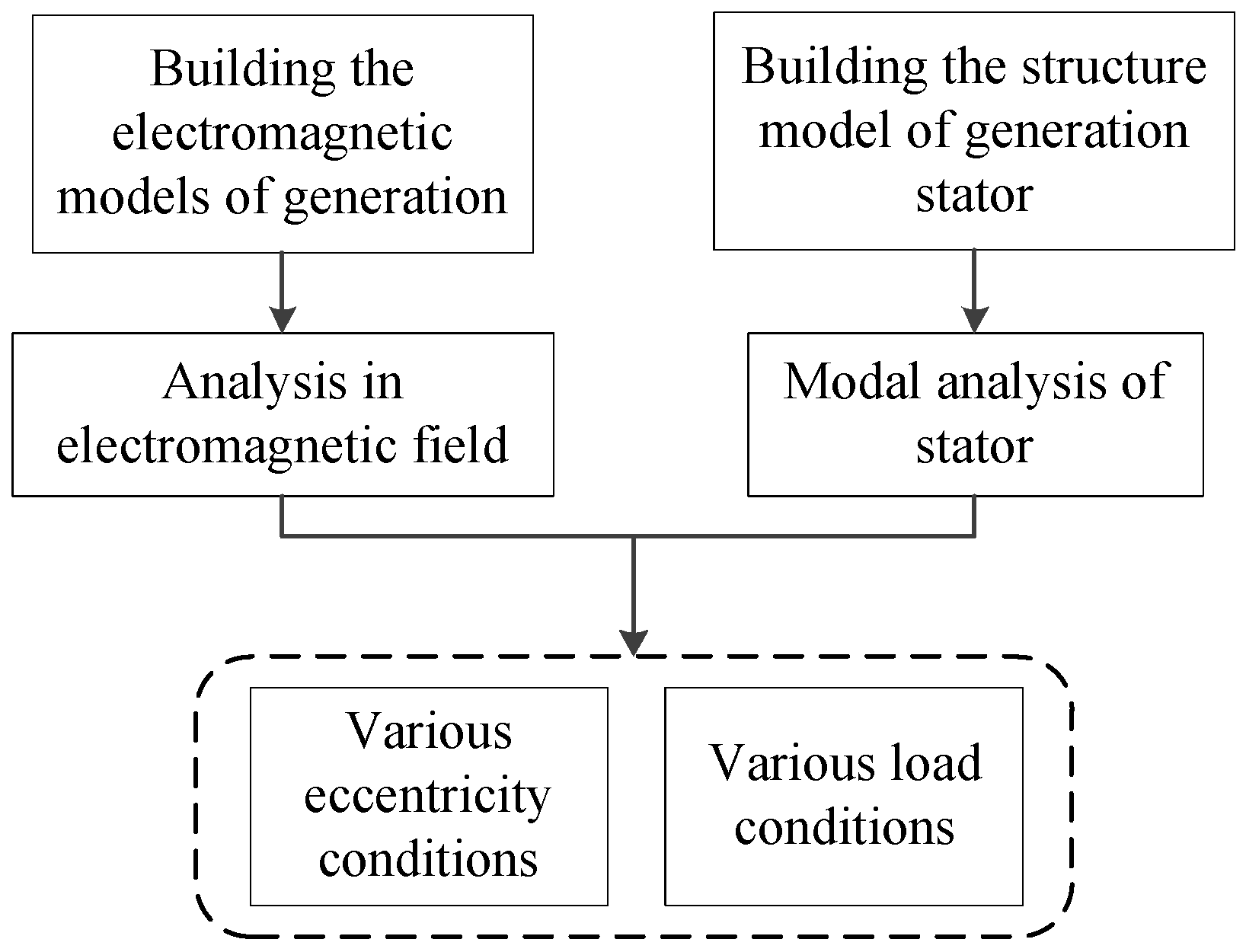
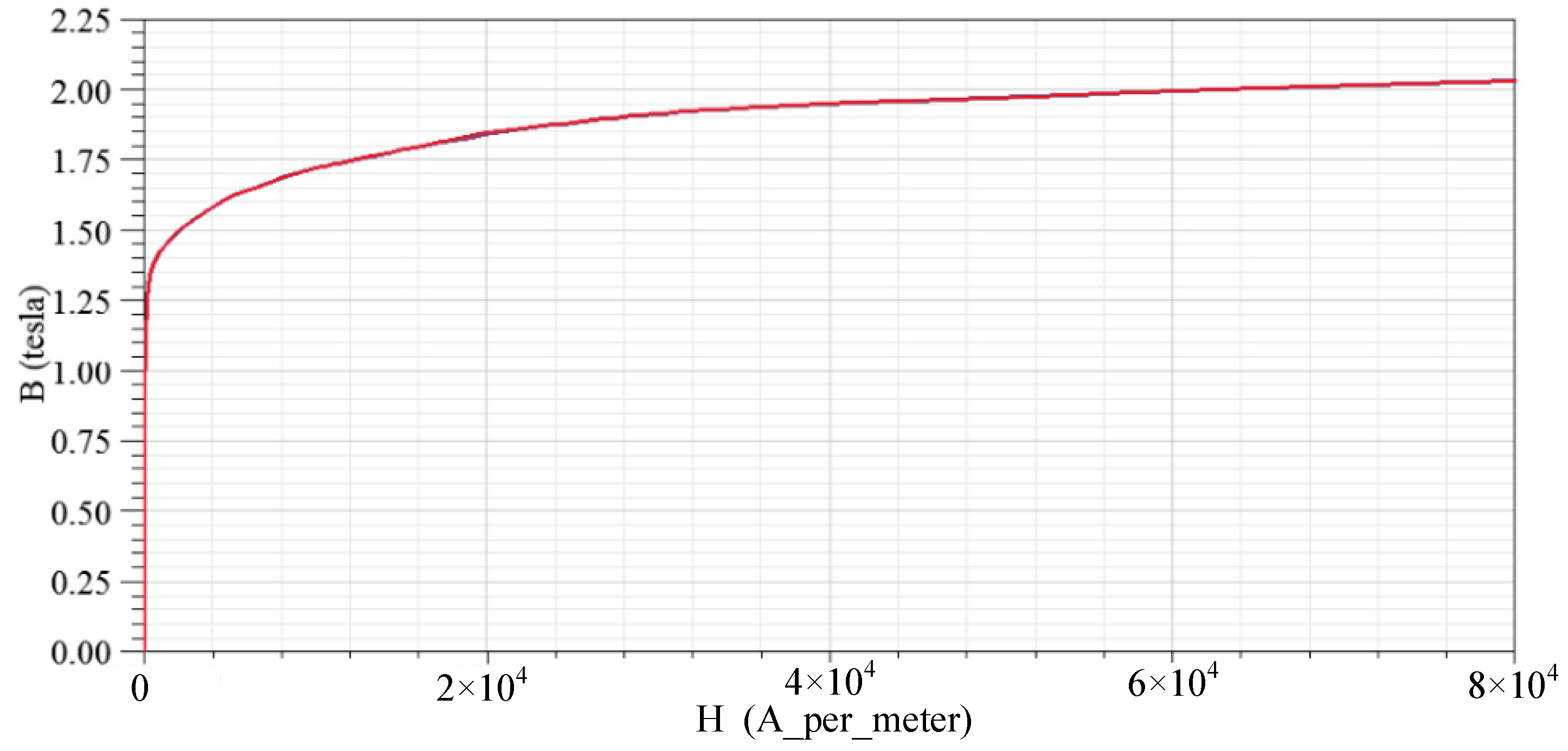
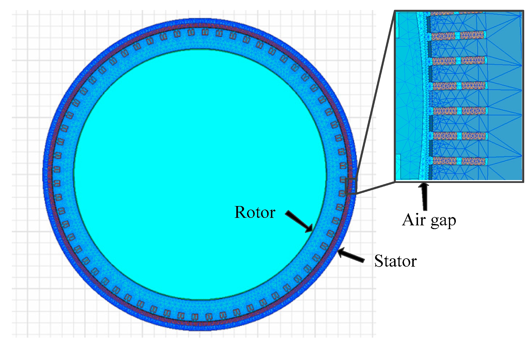
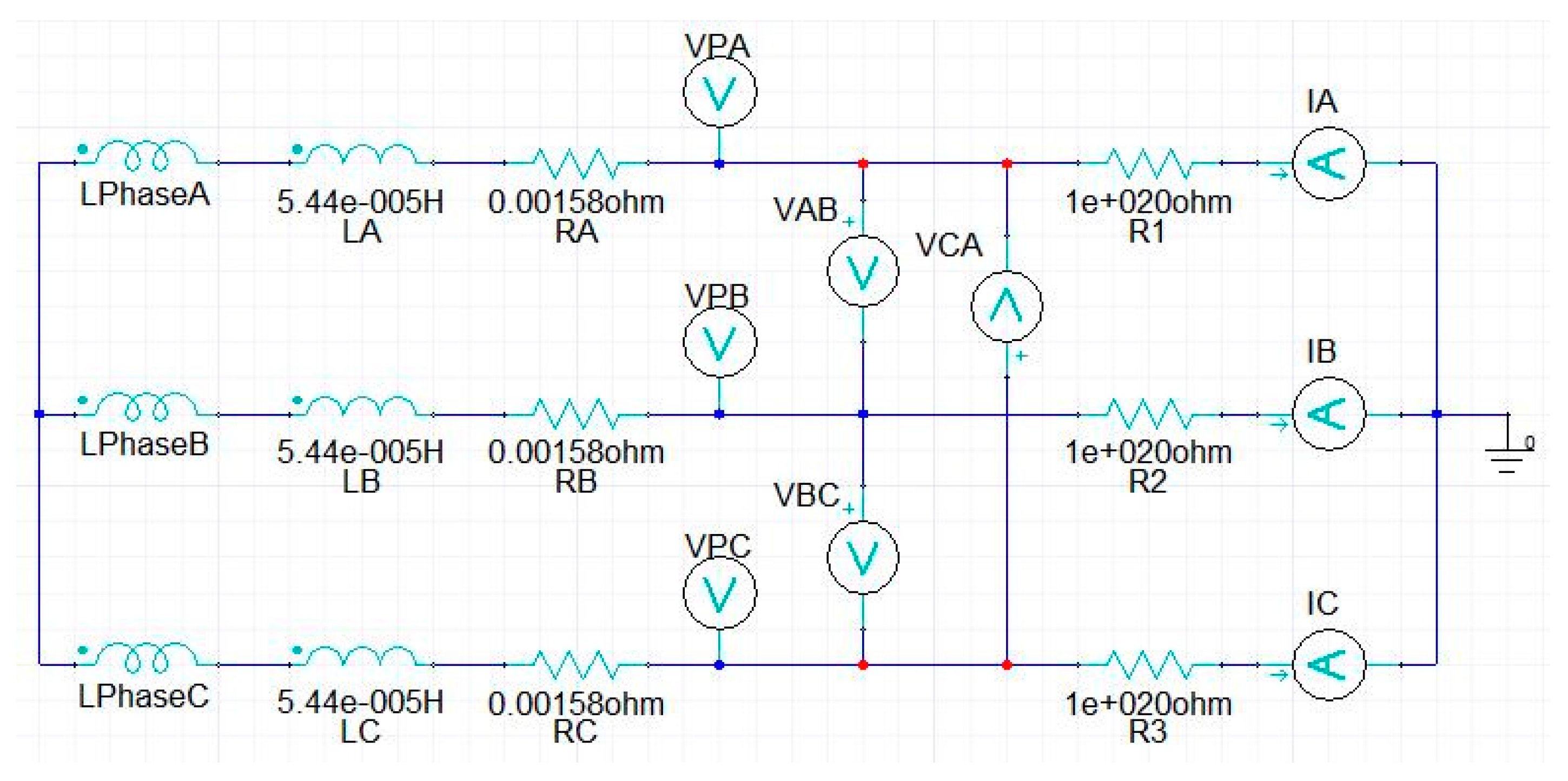
2. Transient 2D Modelling

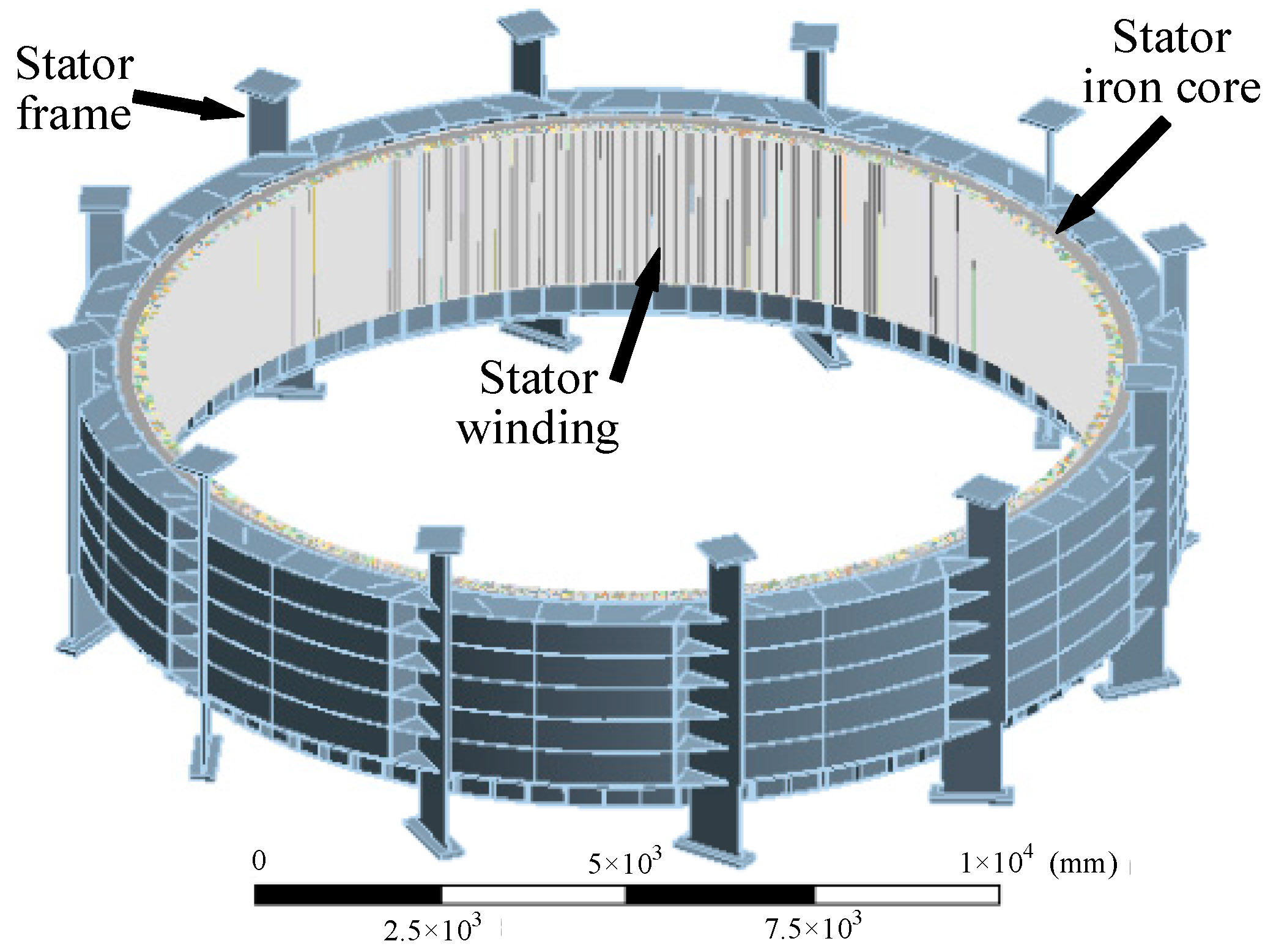
2.1. The Basic Model of the Hydropower Generator

The large hydropower generator is a three-phase synchronous salient pole type generator, which has an external diameter of more than 13 m and less than 5 m high. The stator iron core is installed on the stator frame while the rotor is fixed by the upper and lower support of the generator. In this study, the simulation of magnetic just forced on stator iron core and rotor.
The main design sizes and the electrical parameters of the large hydro generator are provided in Table 1.
The magnetic nonlinearity of the iron core (50W250) represented by the magnetization curves shown in Figure 2 which was used for the stator core. The rotor core was made of steel sheets (R345, R450). In the generator model, copper windings were used in the stator, whereas field coils were employed in the rotor.
The generator basic finite element model is presented as rotational symmetry in structures. The number of windings per phase per pole is 11/4. The 2D electromagnetic FEM model and mesh of the hydro generator is shown in Figure 3.
In the rotor, the field coils were excited by direct current (DC) to generate a strong electromagnetic field between stator and rotor. However, the excitation of the windings in the stator slots involves two approaches: (1) Sinusoidal voltage source excitation and (2) external circuit excitation. The former is easy to achieve, but it cannot simulate variable load conditions, while external circuit excitation cannot only emulate different loads by changing the load resistance, but also make the simulation results stabilize rapidly, which saves computation time and storage space. Therefore, an external circuit was used to supply the excitation to the stator windings. To add a terminal for the windings in the stator, the driving circuit in this design consisted of three phase windings in series with resistors and inductance coils. The external circuit of stator windings is shown in Figure 4.
Figure 4 shows the external circuit of the large hydropower generator transient model. The LPhaseA, LPhaseB and LPhaseC of the winding correspond to the three phases of the stator windings. The stator winding line voltages are, respectively, determined by voltmeters VAB, VBC and VCA. The voltage meters VA, VB and VC are used to measure the phase voltages. The stator winding line currents are measured by ammeters IA, IC and IB. The line currents and phase currents are equal in this generator because of the Wye connection of the stator windings. RA, RB, and RC represent the stator winding resistances. The inductance coils LA, LB, and LC which are behind each phase of the stator windings refer to leakage reactance of armature end windings. The resistors R1, R2 and R3 are used to imitate an active load of the generator. The resistors are switched by adjusting the value to 10 20   Ω . for an open-circuit condition. The rated load condition of the load resistance R is determined by [12]
R = U N 2 / P .
where U N represents the rated voltage and P is the load of the generator. The simulation of different load conditions can be achieved by adjusting the load resistances following Formula (1). In addition, the field current of generation would be changed as load decreases under load conditions. Therefore, the repeated verification is necessary to ensure the load simulation accuracy.

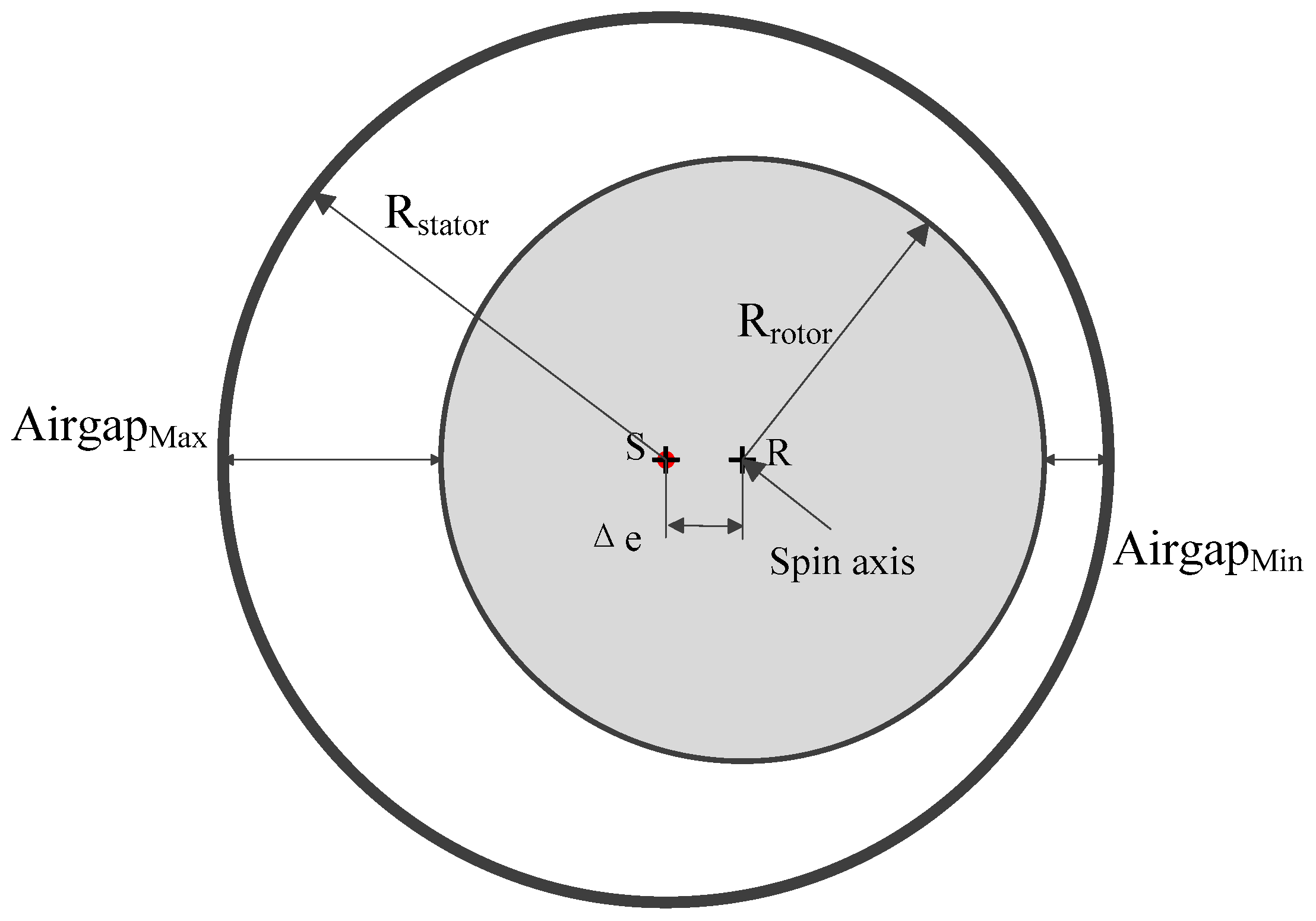
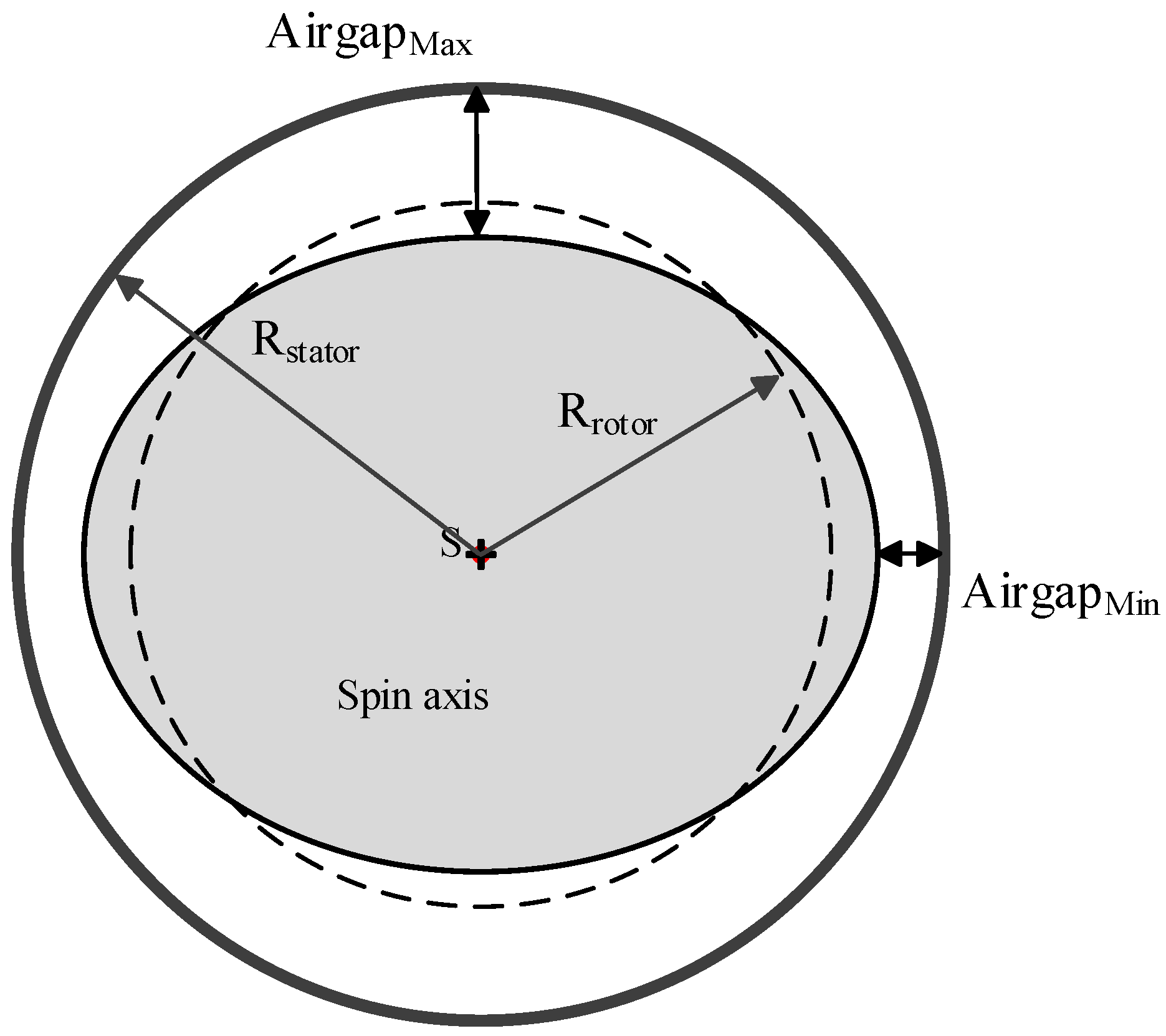
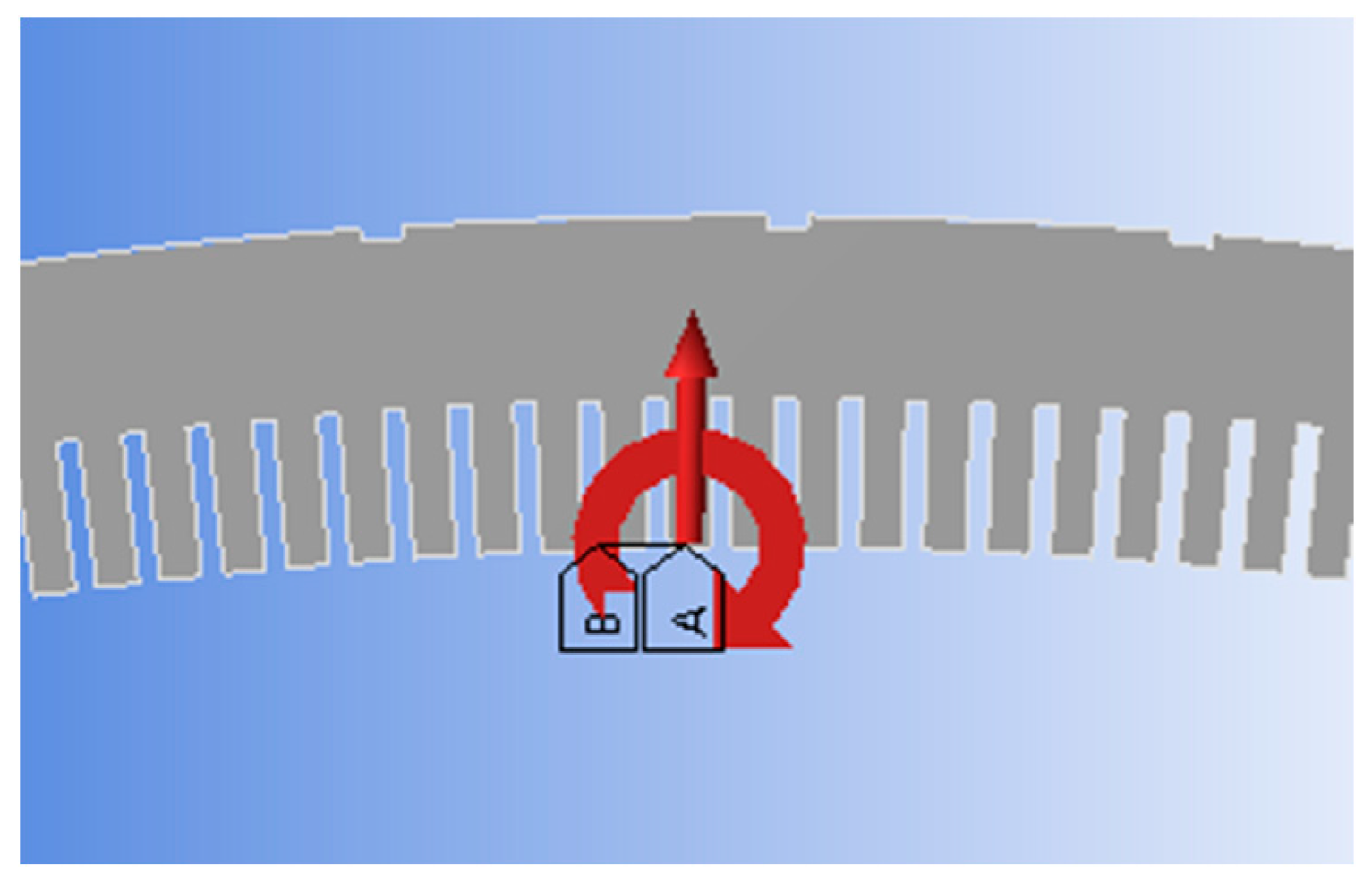
2.2. Rotor Eccentricity and Rotor Ellipse Deformation Models of the Hydropower Generator

There are two types of rotor eccentricity in the hydropower generator. One type of rotor eccentricity is static eccentricity, which describes the rotor axis existence deviation, when the rotor is rotating around its own axis. This type of eccentricity is mainly caused by manufacturing and assembly errors. The static eccentricity model was modelled by offsetting the stator and keeping the center of rotation constant, as shown in Figure 5. The other type of eccentricity is dynamic eccentricity, which performs as a rotation around the stator center, but not its own center. This type of eccentricity is produced by manufacturing errors in the rotor and the wear [13]. It was modelled as offsetting the rotor and keeping the center of rotation coincident with the center of the stator, as shown in Figure 6.
Figure 5 shows the static eccentricity model of the hydropower generator, where the rotor center (A) is not aligned with the stator center (B). In this model, the rotor center (A) is the spin axis of the rotor, while the positions of the min air gap and max air gap are fixed with the rotor rotation.
Figure 6 shows the model of hydropower generator where the stator center (B) is the spin axis of the rotor, so the position of min air gap and max air gap varies with the rotor rotation. The length between A and B is the level of eccentricity ( Δ e ). The level of rotor eccentricity is defined as follows [9]:
e = Δ e g × 100 % .
where e represents the eccentricity ratio of the air gap, Δ e is the offset between the rotor center and the stator center, and g is the air gap length of the normal generator model. This paper assumed that the maximum eccentricity ratio of both static eccentricity and dynamic eccentricity reach 20%.
In some cases, the rotor of the large hydro generator may occur elliptical deformation during daily operation. The deformation was mostly caused by the thermal deformation or looseness of the bolt and welding. So the elliptical deformation condition should not be ignored. In this paper, the ellipse deformation model was built as Figure 7. In this model, the longest radius of ellipse was larger 1.9 mm than normal, while the minimum radius was shorter 1.9 mm.

3. Simulation Principle of Electromagnetic Field

3.1. Transient Electromagnetic Analysis

The transient time-stepping electromagnetic simulation of the hydro-generator is made by using Maxwell 2D. The electromagnetic governing equation for this 2D electromagnetic field problem can be formulated in terms of the magnetic vector potential A and current density J in the armature and field windings in the generator as follows:
x ( v A x ) + y ( v A y ) = J + σ A t
where v is the material reluctivity, A ( x , y ) z ^ is the magnetic vector potential, where z ^ is the unit vector in the z-direction, x and y are the Cartesian coordinates in the radial cross-section plane of the machine and the z-axis lies along the rotating axis of the machine, J is the current density vector, σ is the conductivity of the studied region. In this non-linear and time dependent equation, the discretization of the time step is needed to consider [14].

3.2. Electromagnetic Force Analysis

The electromagnetic field in the air gap of the generator causes electromagnetic force over the surface of the stator teeth, which could be computed by integrating the electromagnetic force density (N/m2). There are three types of methods, such as the Lorentz force, principle of virtual work and maxwell stress tensor (MST) method, which can be used to calculate the electromagnetic force density. The MST method was used to solve the electromagnetic force in this paper. Because only this method could solve the details of the electromagnetic force density distribution on the stator teeth surface, which is necessary to the vibration simulation of the generator based on this method, the electromagnetic force density F on the surface of the stator teeth can be described as [15]:
F = 1 2 μ 0 ( B n 2 B t 2 ) × n + 1 μ 0 B n B t × t .
where F is the electromagnetic force density (N/m2), μ 0 is the permeability of the air, B n and B t are the normal and tangential components of the flux density on the load at the inner surface of stator teeth, respectively. The parameters n and t are the unit vectors in the normal and tangential direction.
A vast amount of research has indicated that the main factor of the stator vibration is radial force on the surface of the tooth tops. For the UMP study, only the radial magnetic force density F r is considered, which is given by:
F r = 1 2 μ 0 ( B n 2 B t 2 ) .

4. The Results of Electromagnetic Simulations

A series of simulations under rotor eccentricity and rotor ellipse deformation conditions were carried out by using FEM in this section. From the results, we can determine the characteristics and differences between the centric rotor, static eccentricity, dynamic eccentricity and rotor ellipse deformation, which is useful for searching vibration resource and fault diagnosis.

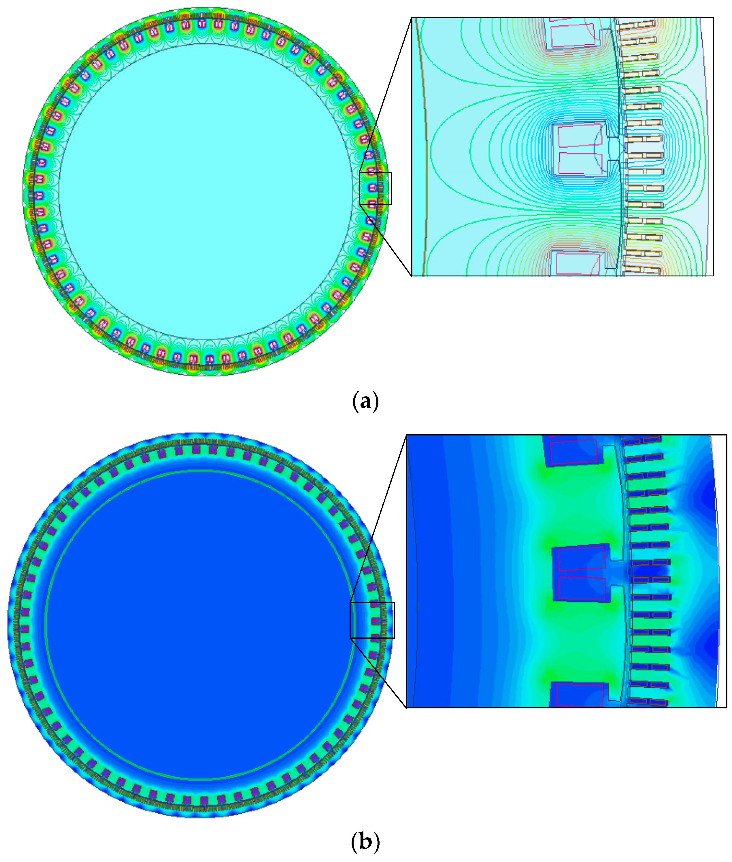
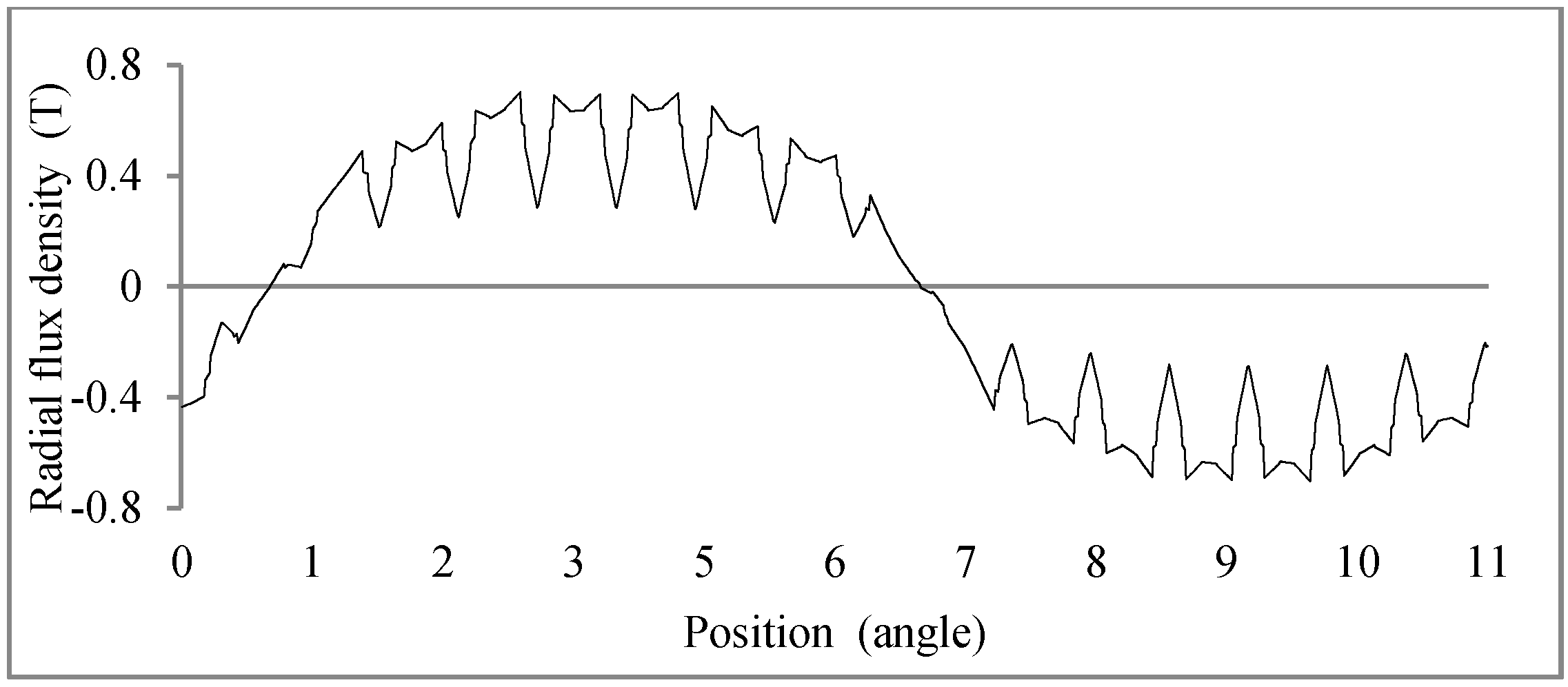
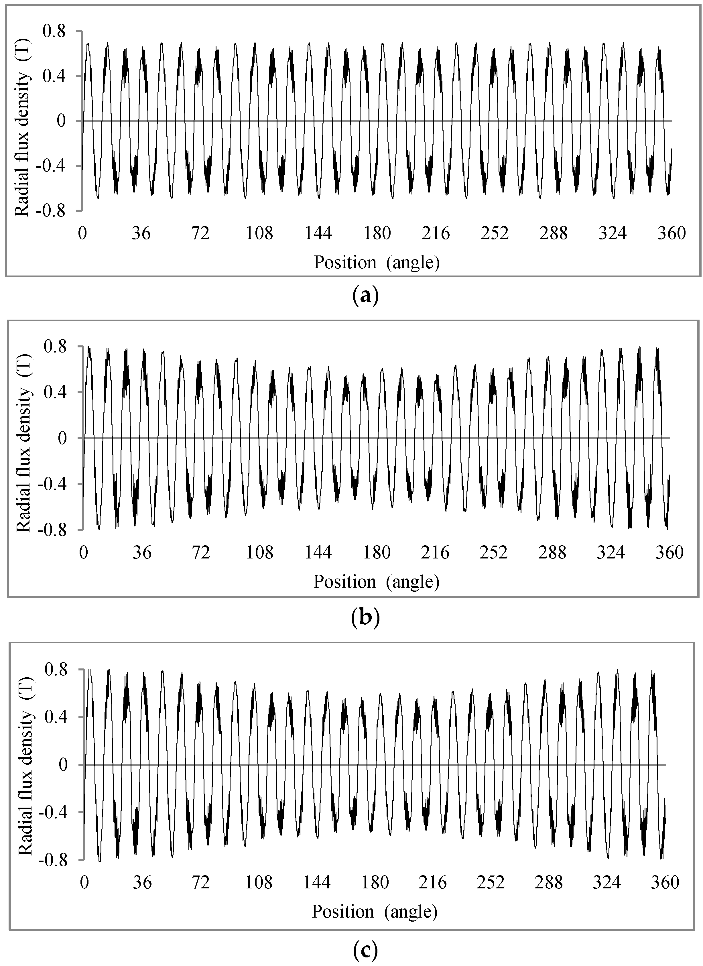
4.1. Flux Density on the Stator Teeth End

The flux distribution produced under the no-load condition is shown in Figure 8.
In this paper, we mainly studied the radial magnetic flux density because the tangential flux density on the surface of stator tooth ends was near zero, so this tangential flux density had little influence on the electromagnetic force on the stator. The distributions in space of radial flux density on the surface of stator under different conditions are presented in Figure 9.
Figure 9 shows the radial flux density distribution on the line of stator tooth ends over one pair of poles. The flux is produced by the centric rotor with no load. The maximum magnetic flux density is near to 0.7 T. The shape is similar to the sine wave, and it can be easily observed that the slots and teeth on stator cause the distortion of the radial flux density wave [16].
Figure 10 presents the radial flux density distribution on the surface of the stator teeth over all of the poles. These simulation results were produced under the centric rotor, static eccentricity dynamic eccentricity and rotor ellipse deformation conditions with no-load. The shape of the radial flux density over the poles is the same with each pair under the centric rotor condition, while the radial flux density of the minimum air gap that is stronger than the radial flux density of maximum air gap under dynamic eccentricity, static eccentricity and rotor ellipse deformation conditions.

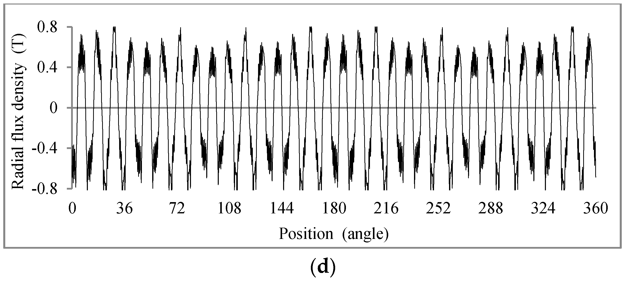
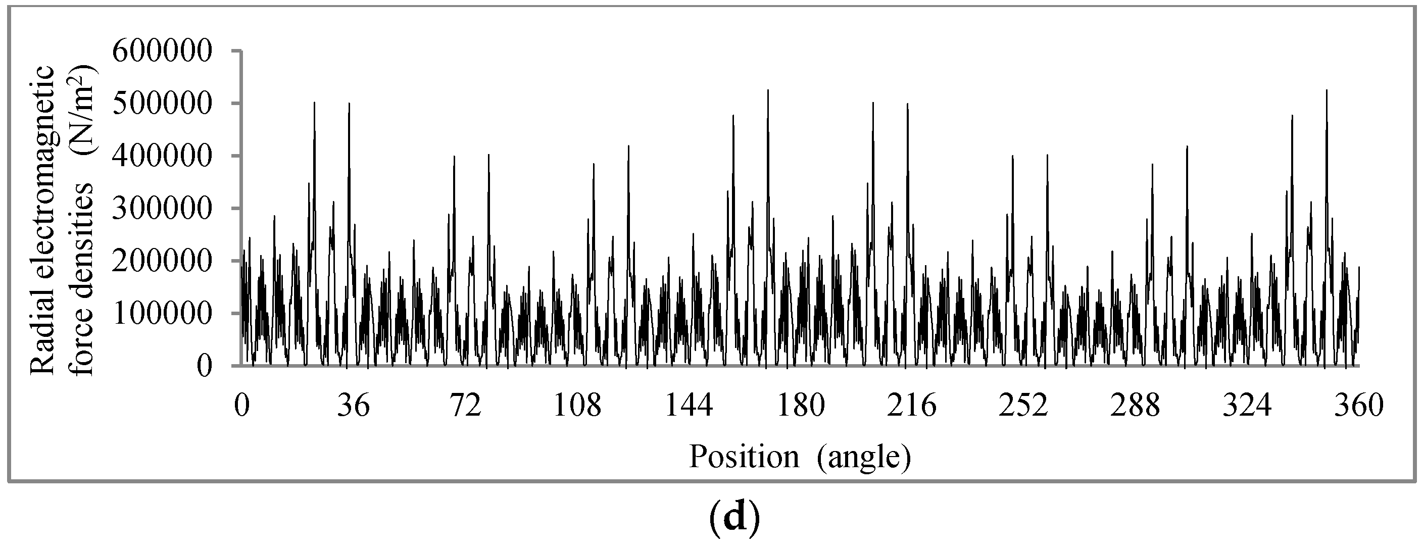
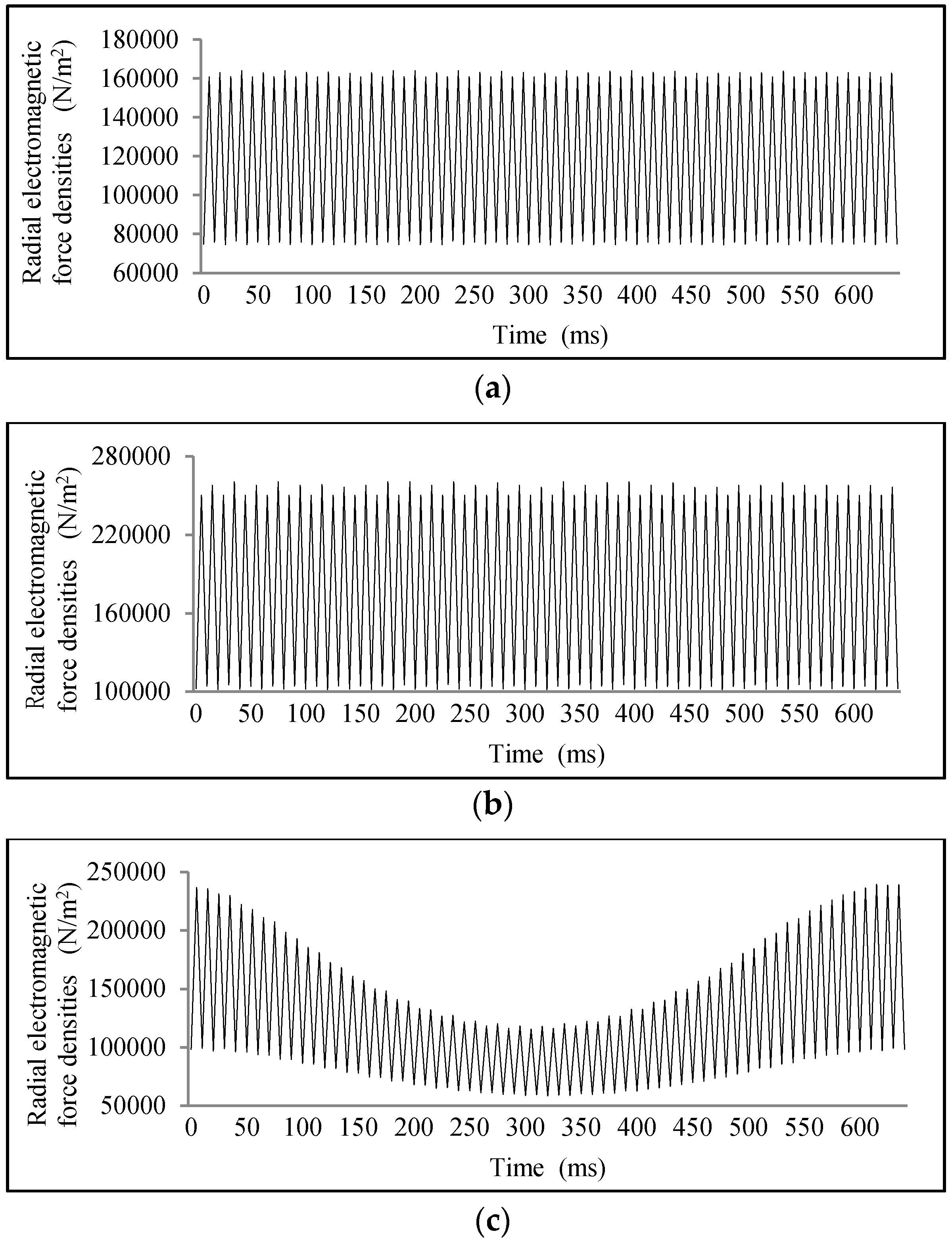
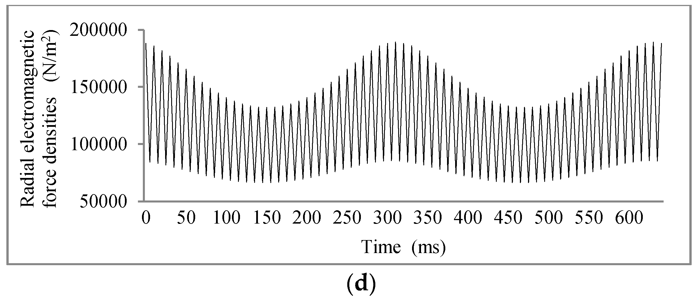
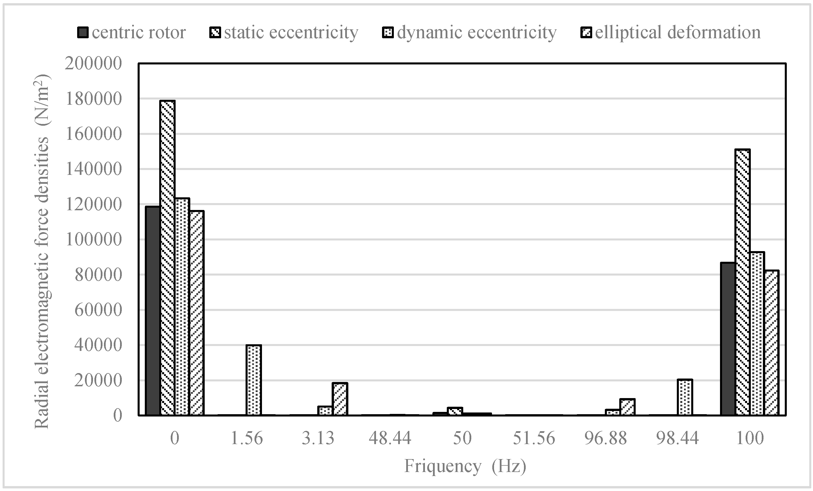
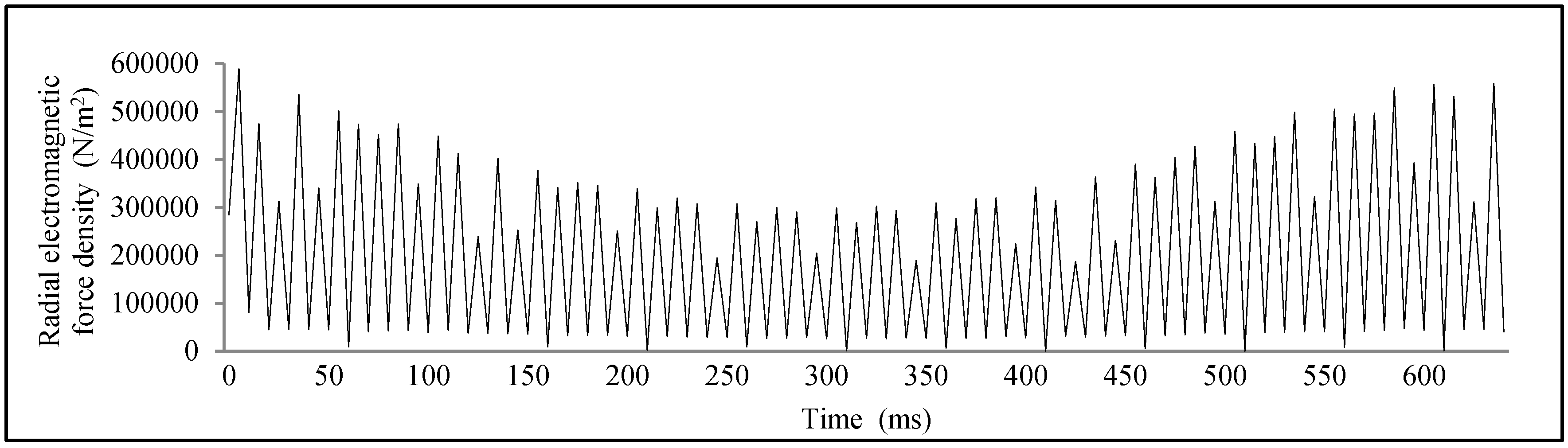
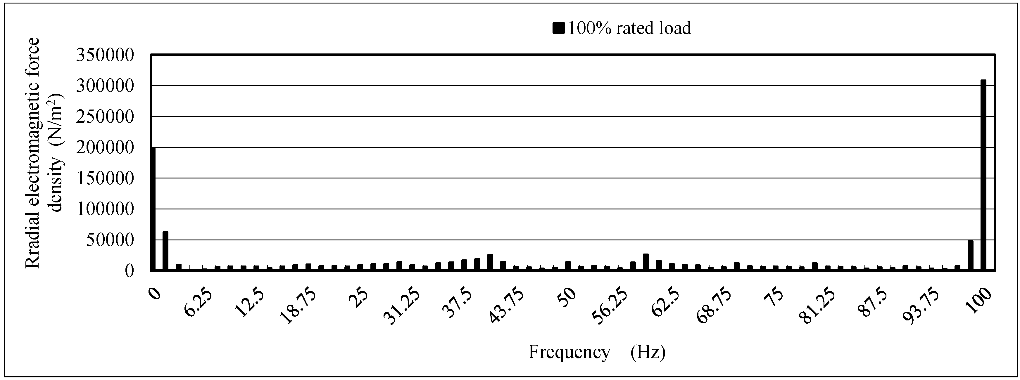
4.2. Electromagnetic Force Density Simulation

Electromagnetic force density on the surface of the stator teeth end is generated through the air gap flux density. The radial component of the electromagnetic force density obtained by the Maxwell stress has a large impact on the electromagnetic vibration of the hydropower generator stator.
As with the flux densities, the electromagnetic force densities were calculated. The electromagnetic force densities of the stator tooth ends in space are shown in Figure 11, demonstrating that the shape of the electromagnetic force densities is similar to the square of the flux density.
The radial electromagnetic force densities of one point on the middle of the stator tooth ends is shown in Figure 12. It shows the distribution in time under different conditions. The wave forms of both centric rotor and rotor static eccentricity models are similar, while the waveform of the rotor dynamic eccentricity and rotor ellipse deformation model have obvious low frequency harmonics.
The significant harmonic components of these radial force densities are shown in Figure 13. The histogram shows that the electromagnetic force waves of these centric rotor and static eccentricity models are mainly composed of 0 Hz and 100 Hz, given as
f = 2 p × f r × n ( n = 0 , 1 , 2 , ... ) .
where f is the fundamental frequency of the centric rotor, p is the number of pole-pairs and f r is the rotating frequency of the generator. n is the constant. However, the amplitude drastically decreases with the increase of n. Other harmonic components are the results of the effect by tooth slots of stator.
The characteristic frequencies are caused by the interaction of the rotor harmonics and the rotational frequency of the rotor. The amplitude of 100 Hz is smaller. In addition, the radial electromagnetic force density of the rotor dynamic eccentricity model has frequencies of 0 Hz, 1.56 Hz, 3.125 Hz, 96.875 Hz, 98.438 Hz and 100 Hz, which are as Formula (7), while the frequency distribution under rotor ellipse deformation condition is as Formula (8).
f d = f ± k × f r ( k = 0 , 1 , 2 , ... ) .
f e = f ± 2 k × f r ( k = 0 , 1 , 2 , ... ) .
where f d is frequency of the dynamic eccentricity model, f e is the frequency of the rotor ellipse deformation model, k is the constant. The amplitude of components became very low when the k is more than 3 [9,17].

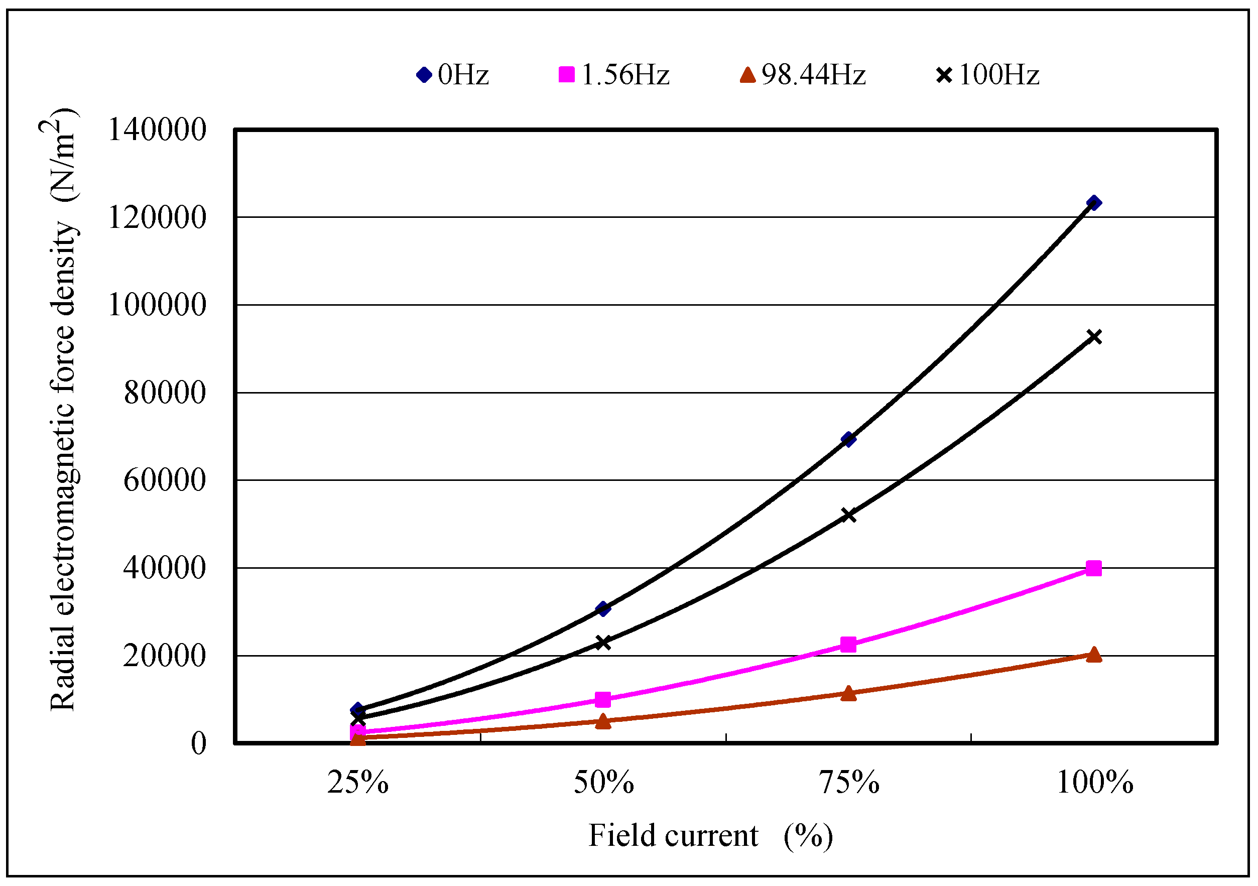
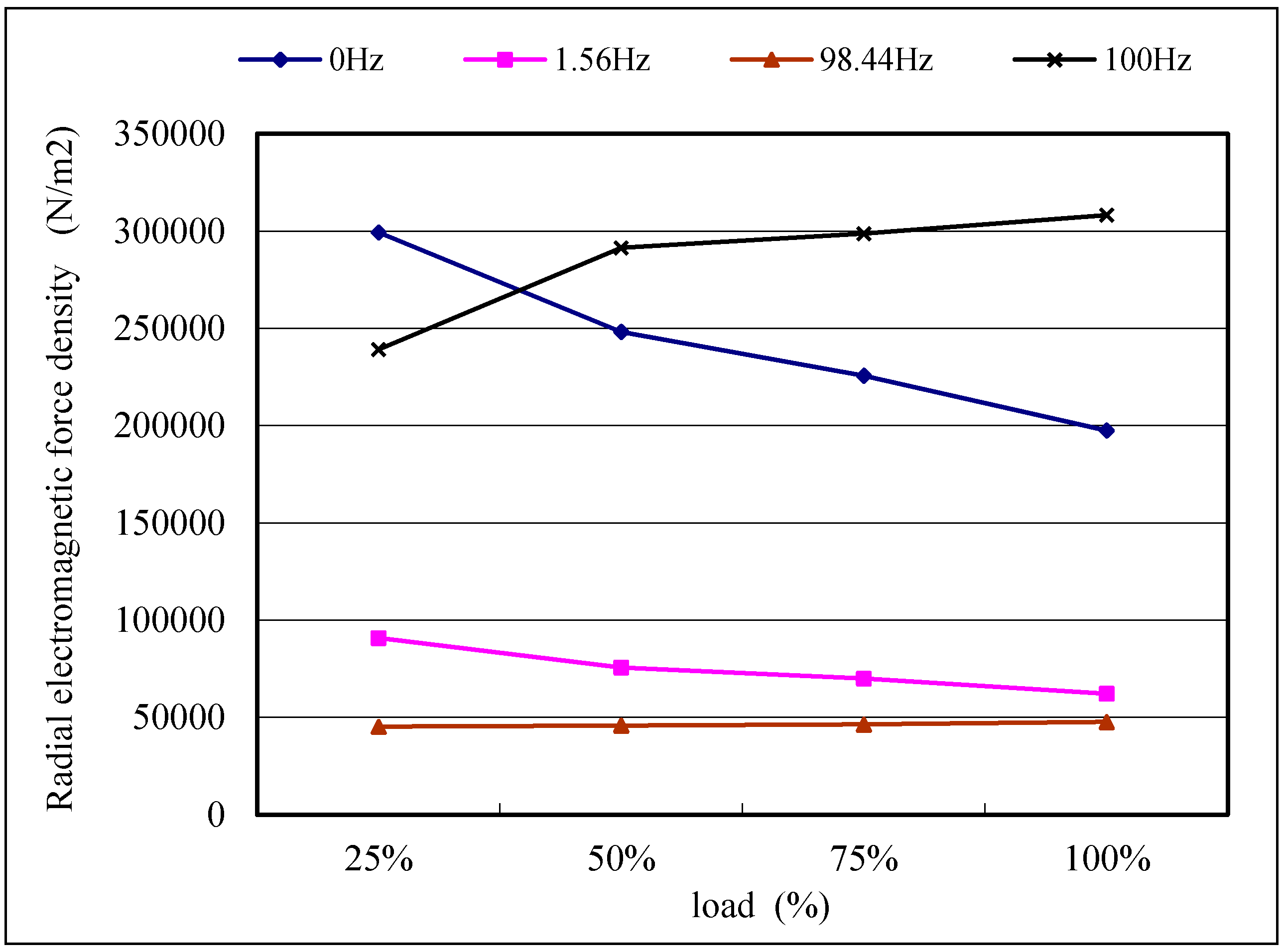
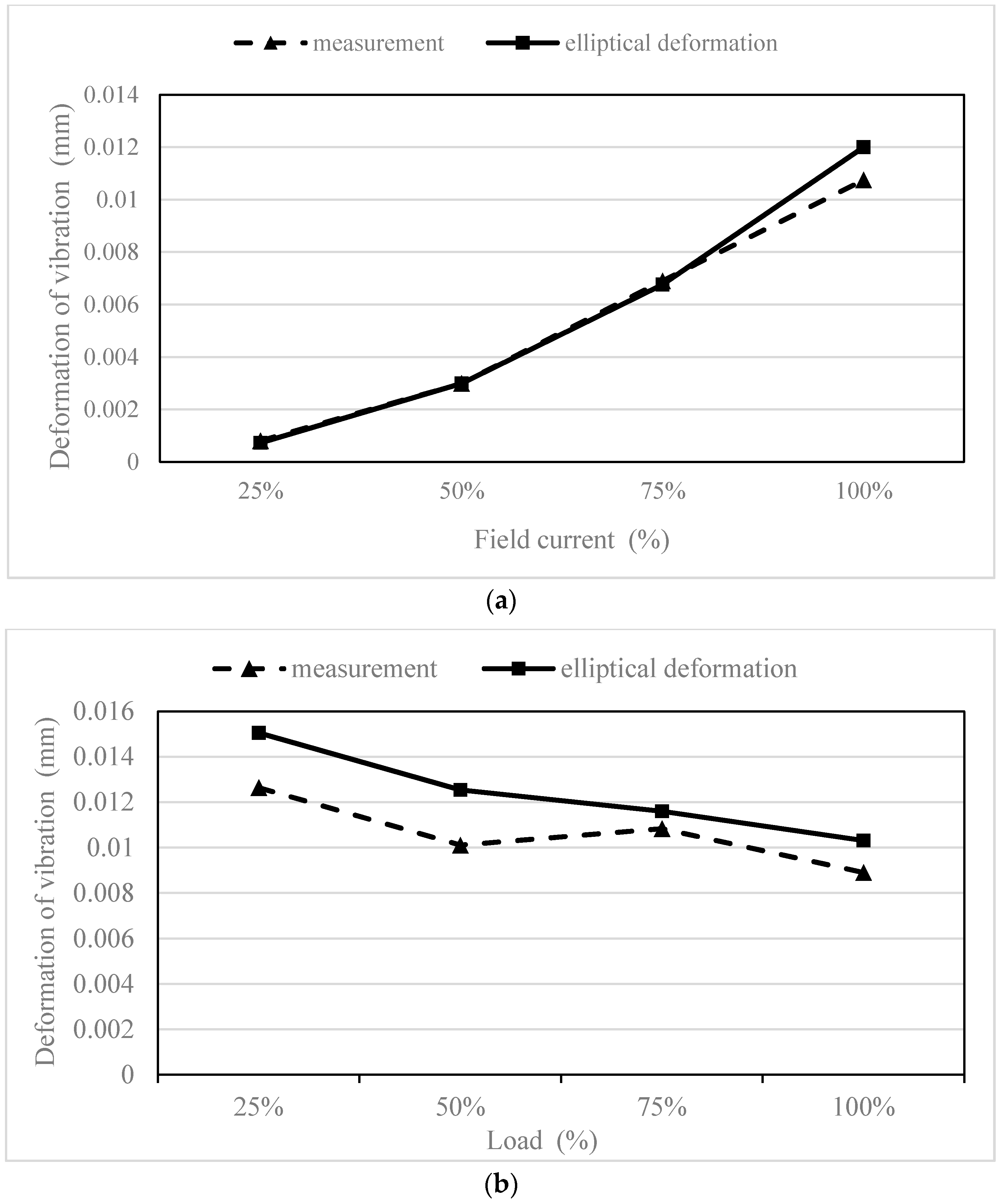
4.3. The Influence of Variable Field Currents and Loads

The dynamic eccentricity is more common and complicated than other conditions, and the dynamic eccentricity is still a research hotspot in rotor eccentricity of electric machinery. Therefore, we chose the dynamic eccentricity model to analyze the influence of various field currents and loads. The harmonic components 0 Hz, 1.56 Hz, 98.44 Hz and 100 Hz of the radial electromagnetic force density are representative under the dynamic eccentricity condition. Therefore, they are used to present the effect of the field currents and loads.
The 0 Hz, 1.56 Hz, 98.44 Hz and 100 Hz component of the radial electromagnetic force density of dynamic eccentricity were calculated versus field currents with no load. The relationship between the radial electromagnetic force density and field current is shown in Figure 14, which clearly demonstrates that all of the harmonic components increase as a quadratic curve following the increase in the field current. The field current has a direct influence on the strength of the electromagnetic force density.
The variable load simulation could be achieved by adjusting the load resistances of the external circuit to achieve 25%, 50%, 75% and 100% rated loads. The values of the load resistances can be determined following Equation (1). The simulation method is used to solve the radial electromagnetic force density of the dynamic eccentricity model at 25%, 50%, 75% and 100% rated loads. The time domain distribution of radial electromagnetic force density under a 100% rated load is shown in Figure 15. Then, the radial electromagnetic force density is Fourier-transformed, and the frequency distribution is shown in Figure 16.
Figure 15 shows that the shape of the radial electromagnetic force density with a 100% rated load under dynamic eccentricity conditions in time is similar to that under no load, except that the former has many distortions because of the armature reaction caused by large currents in the stator windings. As shown in Figure 16, the fast Fourier transformation (FFT) result of the radial electromagnetic force density follows (7). However, the high harmonic components of the rated load are much larger than those of no load. In addition, the amplitude of 100 Hz is bigger than that of 0 Hz under the rated load condition, which is contrary to the no load condition. The variation law of representative harmonic components of the radial electromagnetic force density with an increasing load is shown in Figure 17.
Figure 17 shows that following the raising of the load, the 0 Hz and 1.56 Hz harmonic components of the radial electromagnetic force density decrease. However, the 98.44 Hz and 100 Hz harmonic components increase. The changes are evident at 0 Hz and 100 Hz because the armature reaction affection decreases as the currents in the stator windings are lowered. However, the sums of these harmonic components at different loads are slightly different. These results show that the load of the generator virtually influences the frequency distribution, while the higher harmonics become stronger with an increasing load. However, the variable load of the generator virtually has little influence on the total force.

5. Electromagnetic Vibration Analysis

The vibration testing experiments of the large hydro generator were carried out to at the Zhexi hydropower station. In these experiments, vibration measurement sensors were adsorbed on the center of generator stator frame surface through permanent magnetic shown in Figure 18. The vibration signals were recorded under variable load and field current conditions. After applying the FFT transform on the signals, the two times rotating frequency was found in it.
The electromagnetic vibration simulation was implemented by using harmonic response analysis, based on the advantage of the harmonic electromagnetic force wave forced on the stator. In addition, the distribution of radial electromagnetic force was assumed to be an axially uniform distribution. Therefore, the two-dimensional electromagnetic simulation and the three-dimensional structure simulation coupled method could be used to analyze electromagnetic vibration. This method could not only saves simulation time but also improves simulation accuracy.

5.1. Principle of Harmonic Response Analysis

The mechanical characteristic of a motor can be described as [2]:
[ M ] { x ¨ } + [ C ] { x ˙ } + [ K ] { x } = { F ( t ) }
It described the relationship between displacement, vector and acceleration in mechanical structure under the external force excitation. In this equation, x is the vector of the displacement, x ˙ is the velocity vector, x ¨ is the acceleration vector, [ M ] is the mass matrix, [ C ] is the damping matrix, [ K ] is the stiffness matrix, and { F ( t ) } is the applied force vector in time domain. In the harmonic response simulation analysis, the F ( t ) and x can be expressed as:
{ F } = { F max e i ψ } e i ω t = ( { F 1 } + i { F 2 } ) e i ω t
{ x } = { x max e i ψ } e i ω t = ( { x 1 } + i { x 2 } ) e i ω t
where ψ is the phase angle of force, and ω is the frequency of force. From Equations (9) and (10), the motion equation of harmonic response analysis is obtained as:
( ω 2 [ M ] + i ω [ C ] + [ K ] ) ( { u 1 } + i { u 2 } ) = ( { F 1 } + i { F 2 } )
In this study, { F 1 } + i { F 2 } is the electromagnetic force harmonics focused on the stator, which only consists of the harmonic components of the calculated local force because the DC component has no effect on the vibration of the stator.

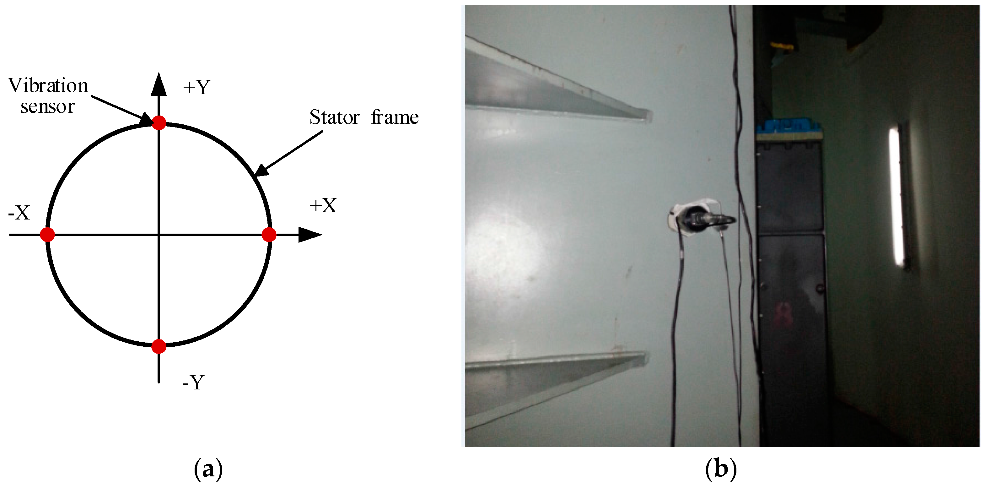
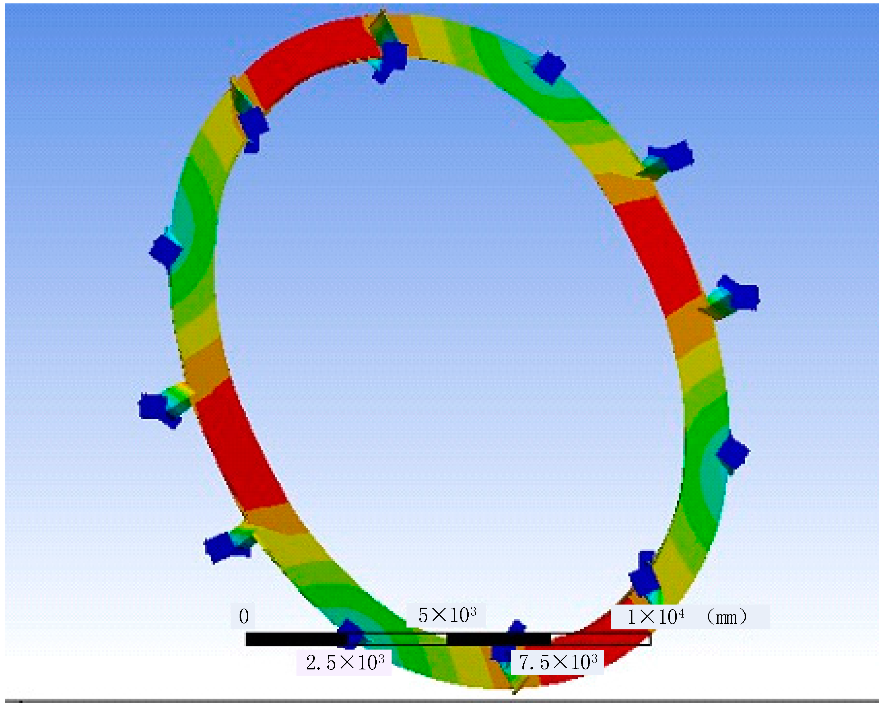
5.2. Geometry Modelling

The stator system of the 250-MW large hydropower generator consists of stator windings, a stator frame and a stator iron core. The details of the stator’s mechanical parameters are provided in Table 2. This structure is large and extremely complex. Therefore, a reasonable simplification was needed for finite element simulation. The stator windings have been completed as independent cable bars with a rectangular cross-section, while the stator iron core was considered as a one-piece structure which made up of homogeneous isotropic material. The stator frame was a combined structure which is welded with plates and beams. Its underside surfaces and upper surfaces were completely fixed. The three-dimensional FEM model of the hydropower generator stator system was emulated by Unigraphics NX (UG), as shown in Figure 19.
The stator modal finite element simulation has been made and the modal shape of the generator stator is shown in Figure 20. The first order nature frequency is 28.476 Hz.

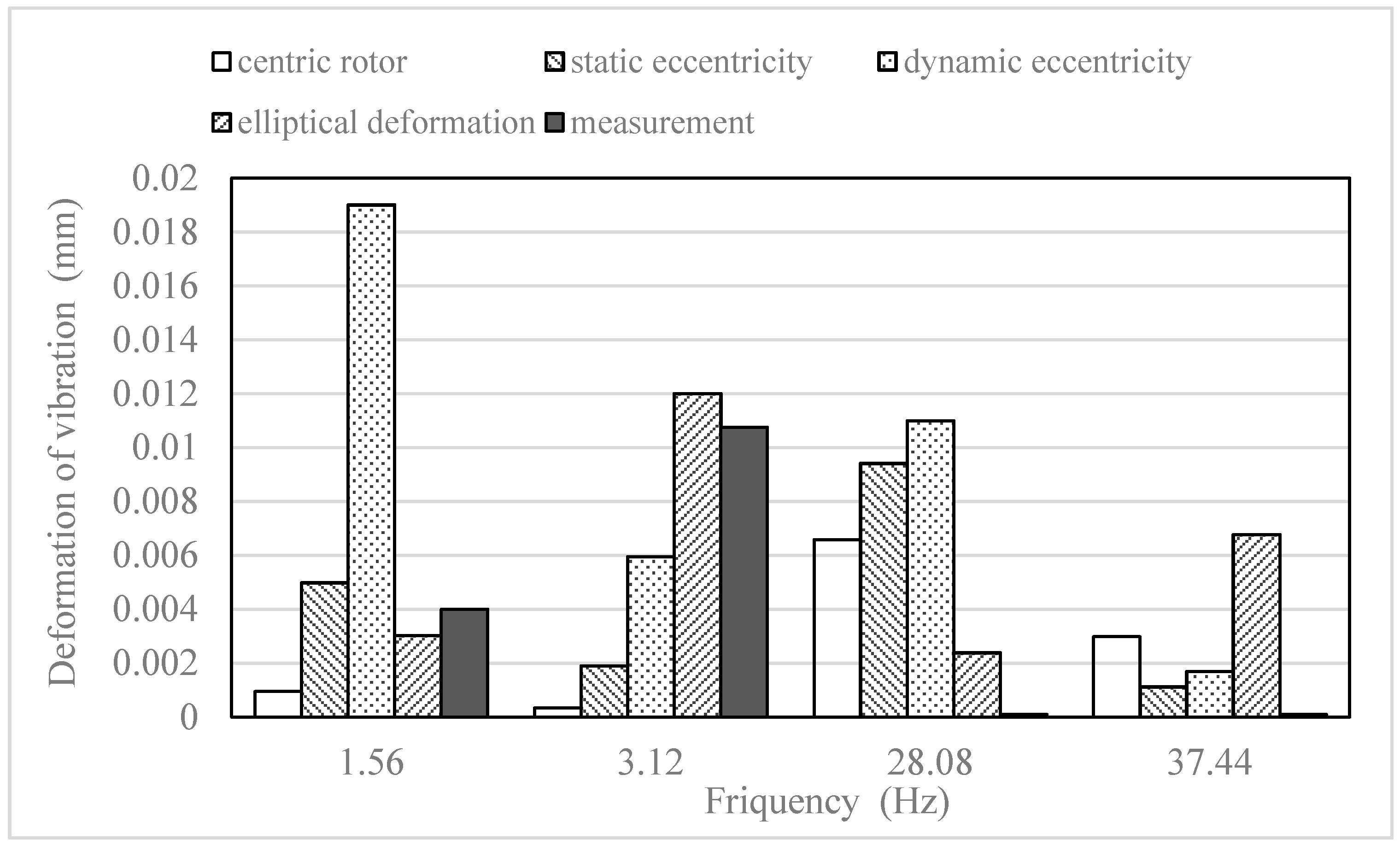
5.3. Electromagnetic Harmonic Response Vibration Coupled Analysis

In this paper, the vibration of the hydropower generator stator in the radial was calculated by using electromagnetic harmonic response coupled analysis. The electromagnetic harmonic response coupled analysis was made as follows. Each harmonic of the exciting force was set to input the source of calculation of the stator deformation. The load of the radial electromagnetic force location is shown in Figure 21. Every harmonic component of both the radial force and bending moments was applied to each tooth as a driving force with phase difference [18].
In this paper, after setting the electromagnetic force on the stator tooth ends, the electromagnetic vibration deformation of rotor eccentricity and rotor elliptical deformation was solved, under various fields current and loads. Many researches shown that most harmful mechanical vibrations for generators is always concentrated in the low frequency area. Hence, the vibration frequency was solved in the range of 1.56–40.56 Hz. The simulation and measurement results were compared in the figure below.
The vibration results of the simulation and measurement under no load were compared in Figure 22. From the simulation result, there is a one-to-one match between each harmonic order of electromagnetic force and each harmonic order of vibration deformation. The peak frequency under dynamic eccentricity model is 1.56 Hz the rotating frequency. However, the peak frequency of rotor elliptical deformation model is 3.12 Hz, the double rotating frequency, which is the same as measurement. So the rotor elliptical deformation simulation and measurement were carried out under various field currents and loads next.
In addition, the simulation vibration has a significant increase at approximately 28 Hz, because the frequency is near the first-order model vibration frequency. However, the vibration of measurement has a little deformation at this frequency. It means that the hammering tests was needed to determinate the natural frequency of the generation stator in the further research.
Figure 23 shows the peak frequency 3.12 Hz of rotor elliptical deformation simulation and measurement under various field currents and loads. From Figure 23a, the measurement results increased nonlinearly following the field current increase, while the rotor deformation simulation had the similar change tendency. From Figure 23b, the vibration amplitude decreased in a certain degree under both simulation and measurement as the load increase. According to the above comparison, the vibration amplitude of peak frequency and changing trend of simulation under rotor elliptical deformation are similar with the measurement. The conclusion could be drawn that, the rotor elliptical deformation phenomena existed in the large hydro generator at the Zhexi hydropower station.

6. Conclusions

In this paper, a centric rotor model, rotor eccentricity model and elliptical deformation models of a 250-MW large hydropower generator have been built and studied under a transient electromagnetic field.
The dependence of the electromagnetic flux and electromagnetic forces, which act on the stator tooth ends, were calculated first. From the results, we found that static eccentricity only affected the radial electromagnetic force density in the space distribution, while the dynamic eccentricity and elliptical deformation models impacted both the space and time distributions.
The vibration testing experiments of the large hydro generator at the Zhexi hydropower station were made under various field currents and loads. In addition, the harmonic response simulations of the generator stator frame were conducted under rotor eccentricity and rotor elliptical deformation conditions. The peak frequency under dynamic eccentricity condition is 1.56 Hz the rotating frequency. While the peak frequency under rotor elliptical deformation condition is 3.12 Hz the double rotating frequency as same as the measurement result. After further analysis, it could be found that the vibration amplitude of peak frequency and changing trend of simulation under rotor elliptical deformation are similar with the measurement result. So the rotor elliptical deformation could be considered as a main source of the large hydro generator vibration at the Zhexi hydropower station. The structure deformation of rotor must be checked in the next overhaul.

Author Contributions

Ruhai li and Chaoshun Li conceived and designed the experiments, performed the experiments; Pengxuan Li and Wei Wei Provide model; Ruhai Li wrote the paper.

Conflicts of Interest

The authors declare no conflict of interest.

References

  1. Pluk, K.J.W.; Jansen, J.W.; Lomonova, E.A. Three-Dimensional Modeling of Shielding of Magnetic Stray Fields based on Superposition of 2-D Models. IEEE Trans. Ind. Appl. 2015, 51, 3656–3665. [Google Scholar] [CrossRef]
  2. Sun, T.; Kim, J.M.; Lee, G.H. Effect of Pole and Slot Combination on Noise and Vibration in Permanent Magnet Synchronous Motor. IEEE Trans. Magn. 2011, 47, 1038–1041. [Google Scholar] [CrossRef]
  3. Koo, M.M.; Choi, J.Y.; Jeong, J.H. Characteristic Analysis of Permanent-Magnet Synchronous Generator with Slotless Stator Structure Considering Magnetic/Mechanical Air Gap Using Semi-3-D Analytical Method. IEEE Trans. Magn. 2015, 51. [Google Scholar] [CrossRef]
  4. Jia, H.; Wang, J.; Cheng, M. Mathematical Model of Radial Suspending Force for a New Stator-Permanent Magnet Bearingless Machine. IEEE Trans. Magn. 2015, 51. [Google Scholar] [CrossRef]
  5. Pennacchi, P.; Frosini, L. Dynamical behaviour of a three-phase generator due to unbalanced magnetic pull. IEE Proc. Electr. Power Appl. 2005, 152, 1389–1400. [Google Scholar] [CrossRef] [Green Version]
  6. Lundstrom, N.L.P.; Aidanpaa, J.O. Dynamic consequences of electromagnetic pull due to deviations in generator shape. J. Sound Vib. 2007, 301, 207–225. [Google Scholar] [CrossRef]
  7. Di, C.; Bao, X.; Wang, H. Modeling and Analysis of Unbalanced Magnetic Pull in Cage Induction Motors with Curved Dynamic Eccentricity. IEEE Trans. Magn. 2015, 51. [Google Scholar] [CrossRef]
  8. Naderi, P. Eccentricity Fault Diagnosis and Torque Ripple Analysis of a Four-pole Synchronous Reluctance Machine in Healthy and Faulty Conditions. Electr. Power Compon. Syst. 2015, 43, 1236–1245. [Google Scholar] [CrossRef]
  9. Dorrell, D.G. Calculation of unbalanced magnetic pull in small cage induction motors with skewed rotors and dynamic rotor eccentricity. IEEE Trans. Energy Convers. 1996, 11, 483–488. [Google Scholar] [CrossRef]
  10. Stoll, R.L. Simple computational model for calculating the unbalanced magnetic pull on a two-pole turbogenerator rotor due to eccentricity. IEE Proc. Electr. Power Appl. 1997, 144, 263–270. [Google Scholar] [CrossRef]
  11. Abdi, S.; Abdi, E.; McMahon, R. Optimization of Magnetic Circuit for Brushless Doubly Fed Machines. IEEE Trans. Energy Convers. 2015, 30, 1611–1619. [Google Scholar] [CrossRef]
  12. Wang, L.; Cheung, R.W.; Ma, Z. Finite-Element Analysis of Unbalanced Magnetic Pull in a Large Hydro-Generator under Practical Operations. IEEE Trans. Magn. 2008, 44, 1558–1561. [Google Scholar] [CrossRef]
  13. Abdi, S.; Abdi, E.; McMahon, R. A Study of Unbalanced Magnetic Pull in Brushless Doubly Fed Machines. IEEE Trans. Energy Convers. 2015, 30, 1218–1227. [Google Scholar] [CrossRef]
  14. Khalf, M.A.; Wamkeue, R.; Aguglia, D. Finite Element Approach for Performances Prediction of a Small. In Proceedings of the 2012 25th IEEE Canadian Conference on Electrical & Computer Engineering (CCECE), Montreal, QC, Canada, 29 April–2 May 2012; Volume 25. [Google Scholar]
  15. Edrington, C.S.; Kaluvagunta, D.C.; Joddar, J.; Fashimi, B. Investigation of electromagnetic force components in SRM under single and multiphase excitation. IEEE Trans. Ind. Appl. 2005, 41, 978–988. [Google Scholar] [CrossRef]
  16. Afsari, S.A.; Heydari, H.; Dianati, B. Cogging Torque Mitigation in Axial Flux Magnetic Gear System based on Skew Effects Using an Improved Quasi 3-D Analytical Method. IEEE Trans. Magn. 2015, 51. [Google Scholar] [CrossRef]
  17. Ishibashi, F.; Noda, S.; Mochizuki, M. Numerical simulation of electromagnetic vibration of small induction motors. IEE Proc. Electr. Power Appl. 1998, 145, 528–534. [Google Scholar] [CrossRef]
  18. Jung, A.W.; Kim, D.J.; Hong, J.P. Experimental Verification and Effects of Step Skewed Rotor Type IPMSM on Vibration and Noise. IEEE Trans. Magn. 2011, 47, 3661–3664. [Google Scholar] [CrossRef]
Figure 1. Flowchart of the simulation.
Energies 10 02155 g001
Figure 2. Magnetization curve of the material 50W250.
Energies 10 02155 g002
Figure 3. The 2D electromagnetic finite element method (FEM) model and mesh of the hydropower generator.
Energies 10 02155 g003
Figure 4. External circuit of hydropower generator stator windings.
Energies 10 02155 g004
Figure 5. Static Eccentricity model.
Energies 10 02155 g005
Figure 6. Dynamic eccentricity model.
Energies 10 02155 g006
Figure 7. Rotor ellipse deformation model.
Energies 10 02155 g007
Figure 8. The flux distribution at the rated load (a) flux lines (b) flux distribution nephogram.
Energies 10 02155 g008
Figure 9. The radial flux density on the surface of stator over one pair of poles in space.
Energies 10 02155 g009
Figure 10. The radial flux densities across the air gap under a no-load field current in space: (a) centric rotor; (b) static eccentricity condition (c) dynamic eccentricity condition (d) rotor ellipse deformation condition.
Energies 10 02155 g010aEnergies 10 02155 g010b
Figure 11. The radial electromagnetic force densities across the air gap under no-load field current in space: (a) centric rotor; (b) static eccentricity condition (c) dynamic eccentricity condition (d) rotor ellipse deformation condition.
Energies 10 02155 g011aEnergies 10 02155 g011b
Figure 12. Radial electromagnetic force densities at the point of stator tooth end under no-load field current in time: (a) centric rotor; (b) static eccentricity condition; (c) dynamic eccentricity condition (d) rotor ellipse deformation condition.
Energies 10 02155 g012aEnergies 10 02155 g012b
Figure 13. Fast Fourier transformation (FFT) of radial electromagnetic force densities with different conditions.
Energies 10 02155 g013
Figure 14. Radial electromagnetic force density following the increase of field current.
Energies 10 02155 g014
Figure 15. The radial electromagnetic force density at the point of the stator tooth end under rated load in time.
Energies 10 02155 g015
Figure 16. FFT of radial electromagnetic force density with dynamic eccentricity conditions.
Energies 10 02155 g016
Figure 17. Radial electromagnetic force density following the increase of load.
Energies 10 02155 g017
Figure 18. The installation position of experiment apparatus for vibration measurement: (a) The distribution of vibration sensors; (b) The installation position of vibration sensors.
Energies 10 02155 g018
Figure 19. The three-dimensional FEM model of the hydropower generator.
Energies 10 02155 g019
Figure 20. The first-order vibration model of the hydropower generator stator.
Energies 10 02155 g020
Figure 21. The parts that are assigned exciting forces.
Energies 10 02155 g021
Figure 22. Amplitude frequency of stator deformation under various conditions at no load current.
Energies 10 02155 g022
Figure 23. Amplitude frequency of stator deformation under the rotor elliptical deformation condition with various loads: (a) The vibrations with various field current; (b) The vibrations with various load.
Energies 10 02155 g023
Table 1. Generator design sizes and electrical parameters.
Parameters (Units)Values
Number of poles64
Number of slots528
Rated Speed (rpm)93.75
Number of phases3
Rated frequency (Hz)50
Air gap thickness (mm)19
Rated Power (MW)250
Rated Line Voltage (kV)15.75
Rated line current (A)10,182.6
Rated Power Factor0.9
Winding ConnectionWye
Coil Pitch7
Table 2. The mechanical parameters of stator.
Parameters (Units)Values
Stator iron coreInternal diameter (mm)12,900
Outside diameter (mm)13,700
Materialcoiled silicon steel sheet
Density (Kg/m3)7650
Young’s Modulus (Pa)2.05 × 10¹¹
Poisson’s Ratio0.25
Stator frameInternal diameter (mm)13,700
Outside diameter (mm)14,900
Materialstructural steel
Density (Kg/m3)7850
Young’s Modulus (Pa)2.0 × 10¹¹
Poisson’s Ratio0.30
WindingMaterialCopper Alloy
Density (Kg/m3)8300
Young’s Modulus (Pa)1.1 × 10¹¹
Poisson’s Ratio0.34

