

Stereoscopic UWB Yagi–Uda Antenna with Stable Gain by Metamaterial for Vehicular 5G Communication

Abstract
:1. Introduction
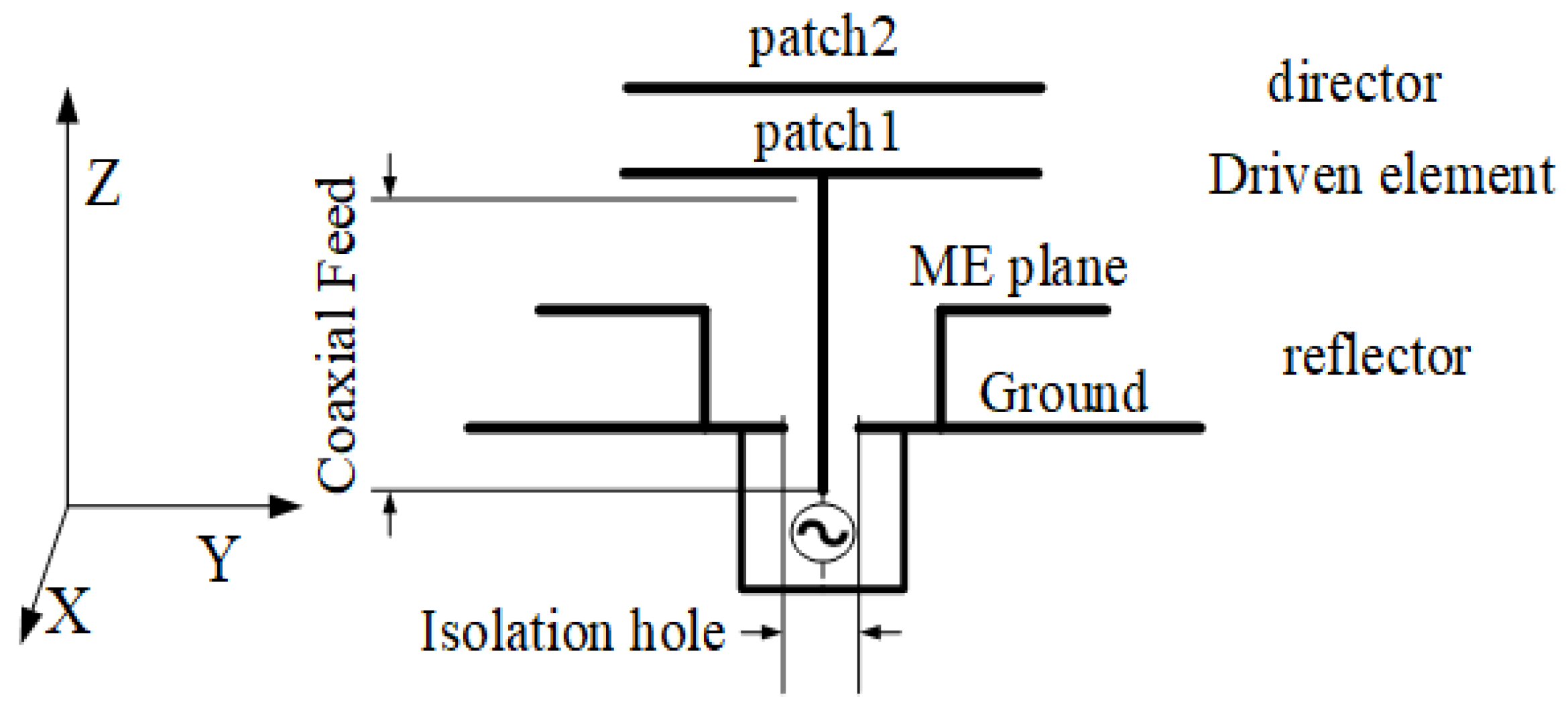
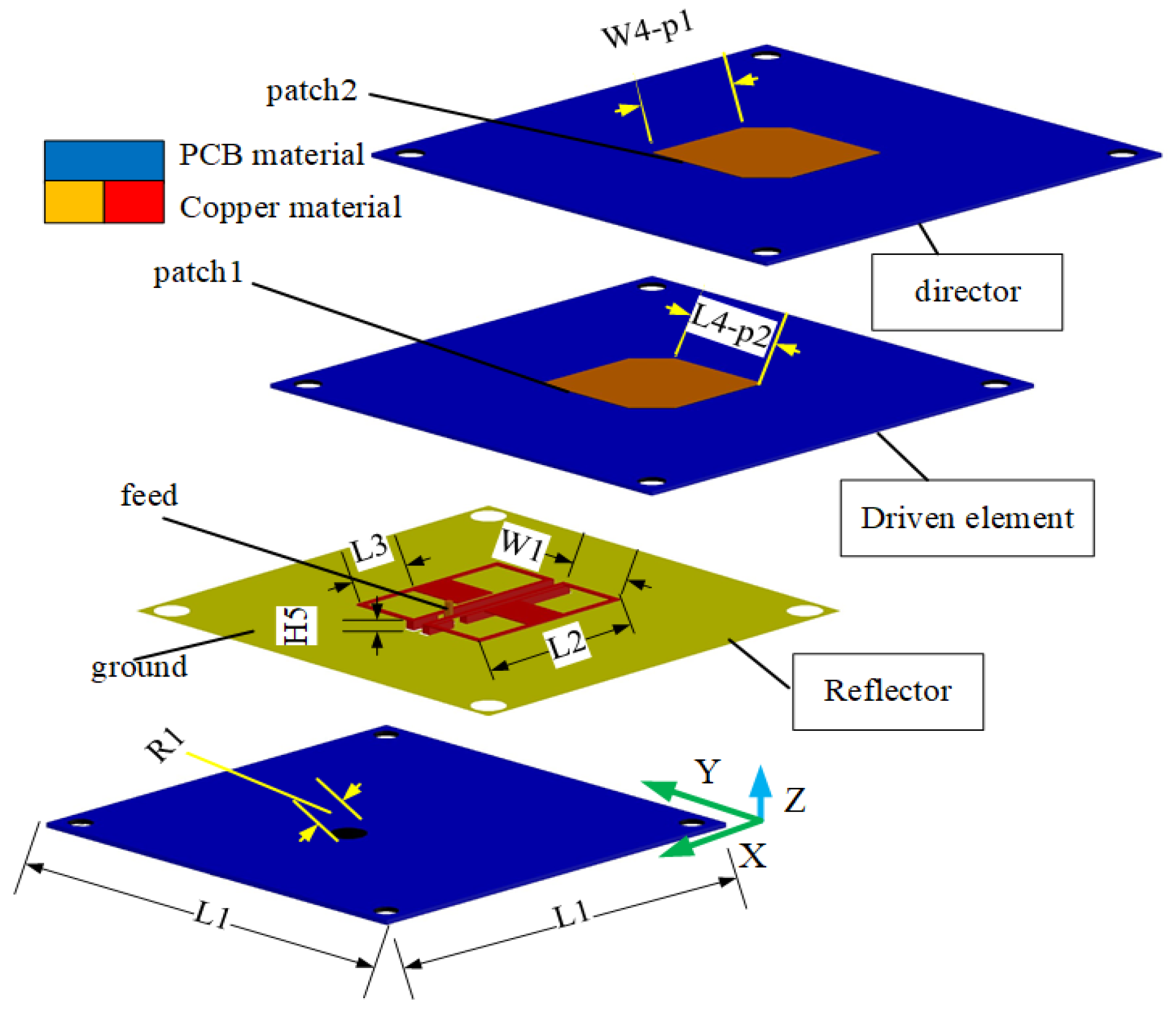
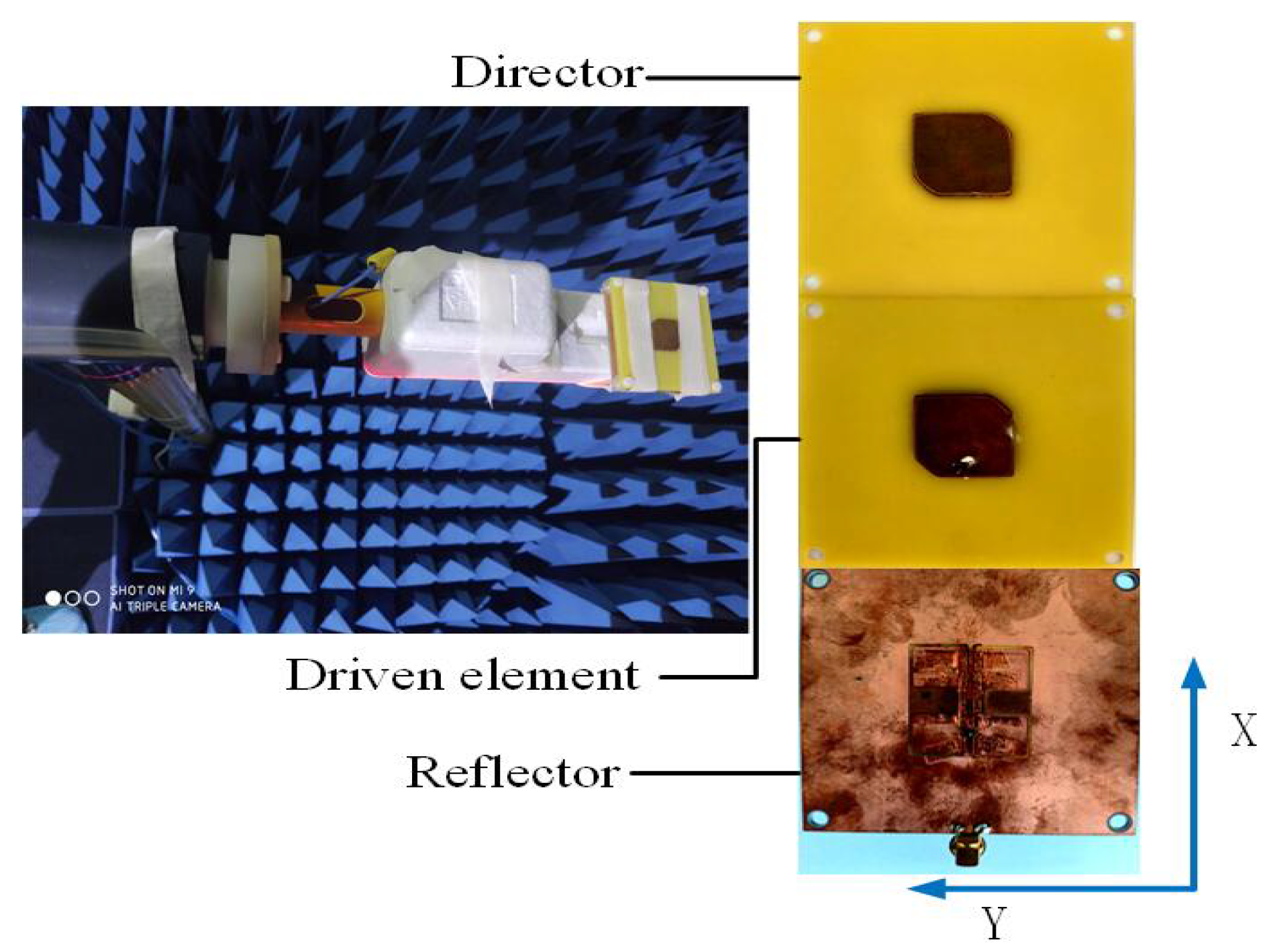
2. Configuration
3. Antenna Design and Analysis
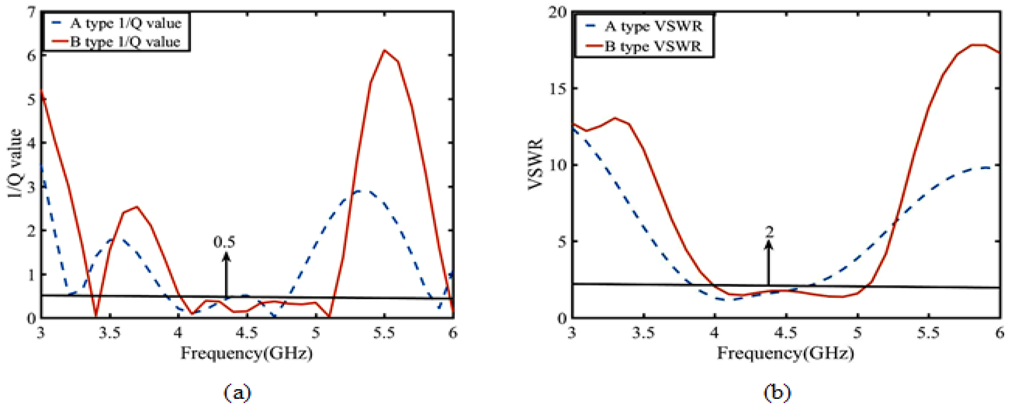
3.1. ME Characteristic Analysis
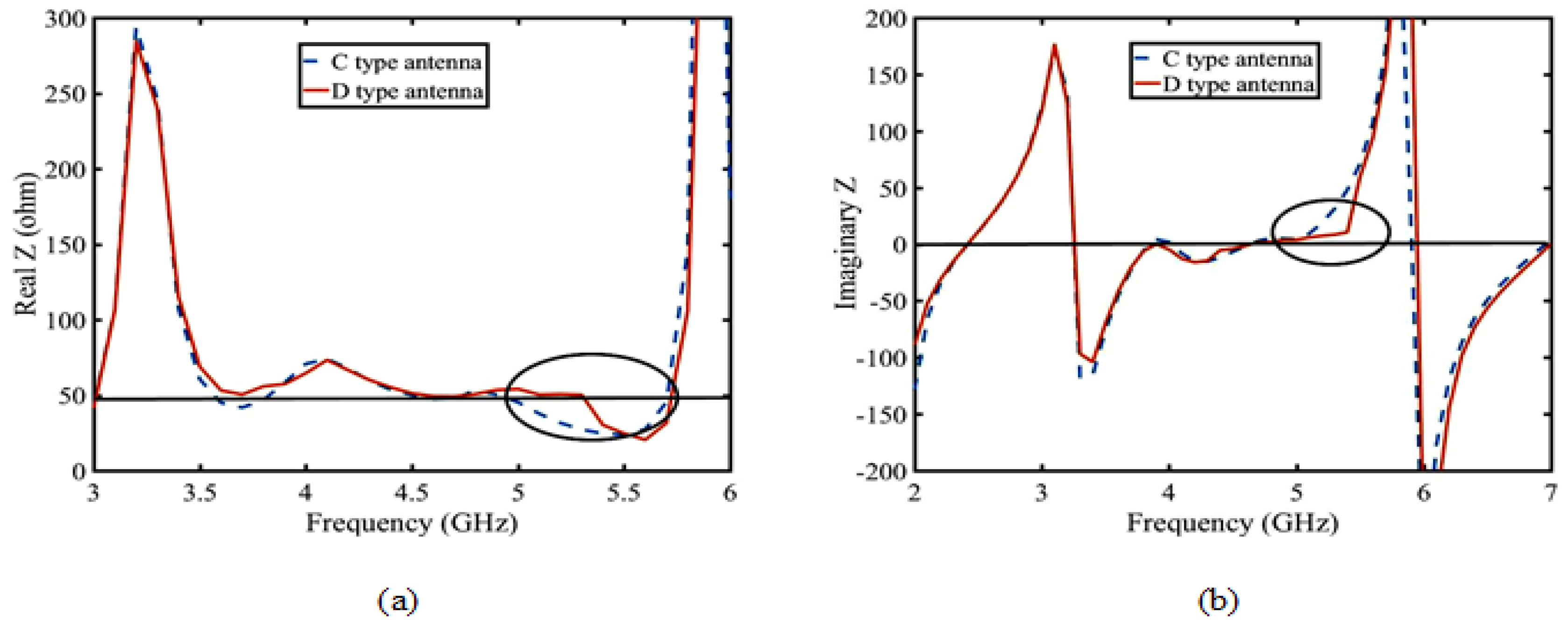
3.2. Design of the Dual-C-Notch NZIM
3.3. Enhancement Suppression Boundary of Gain
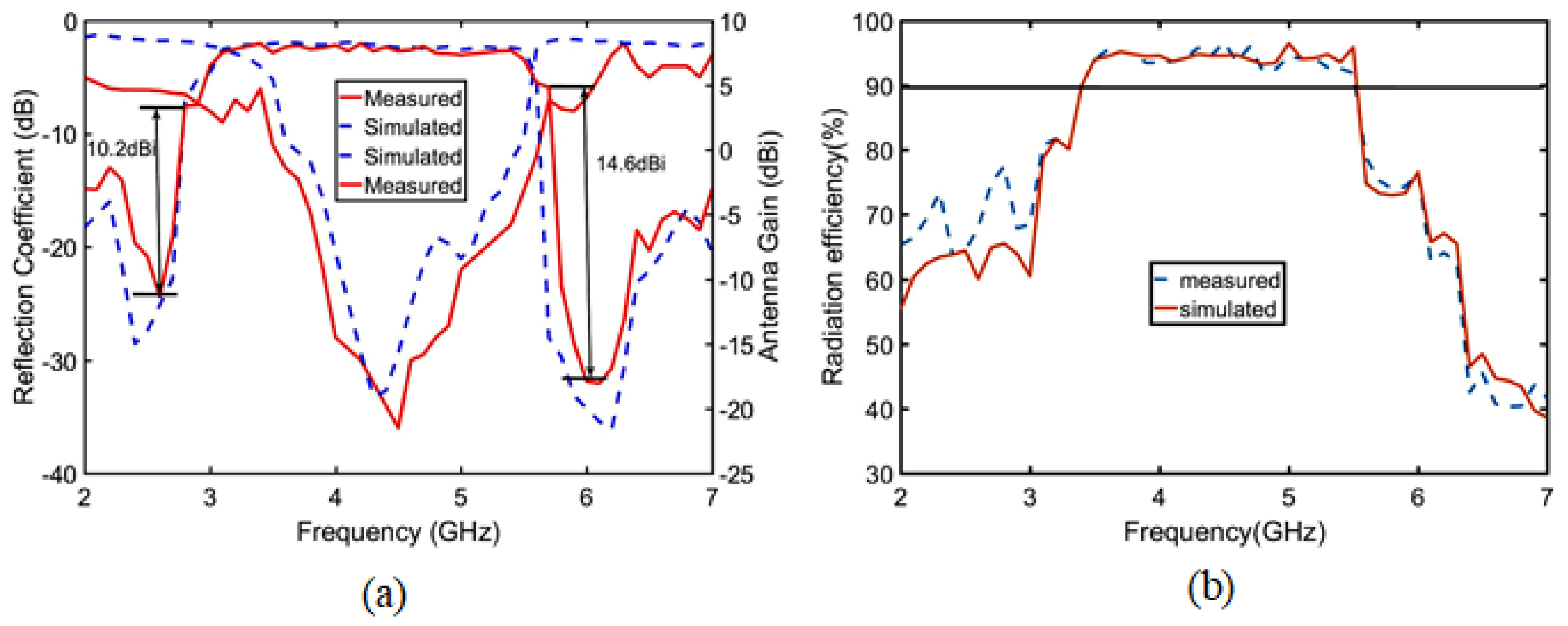
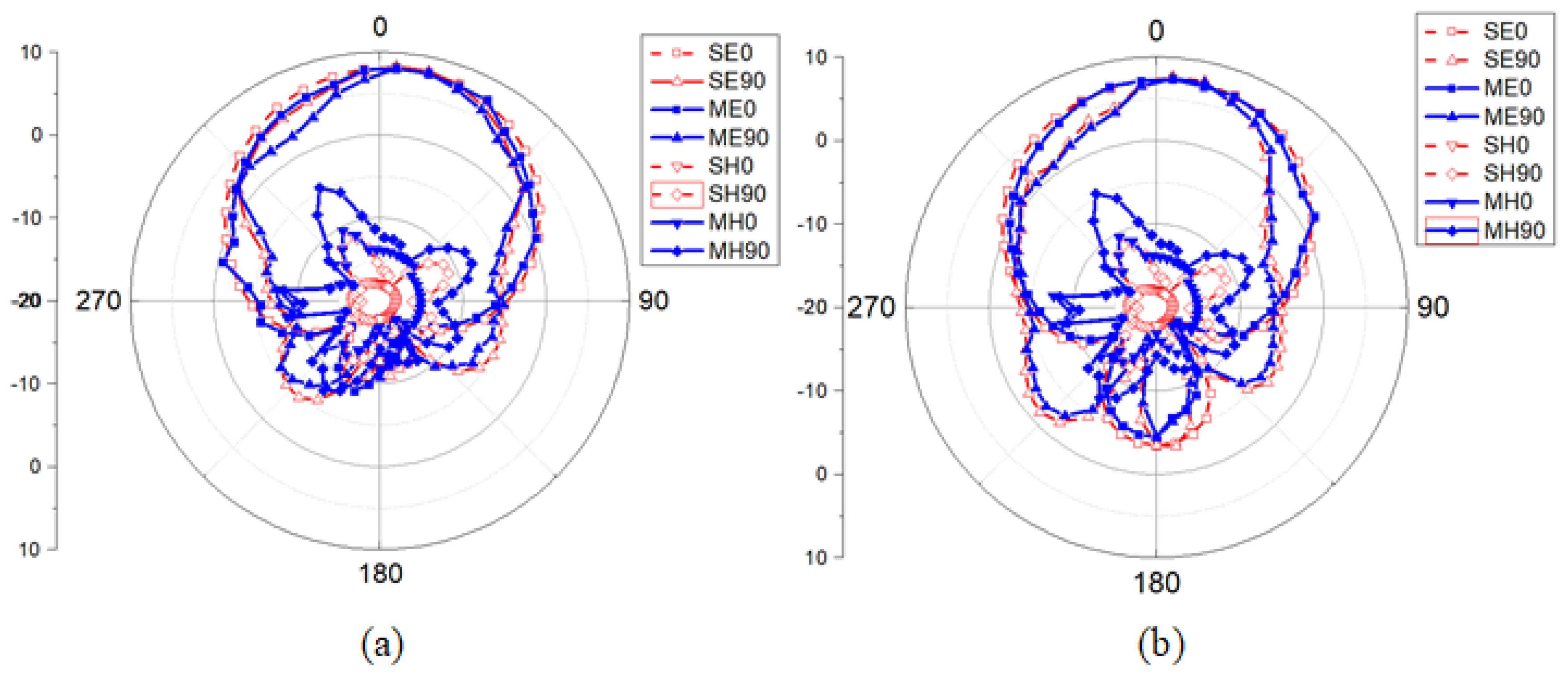
4. Measured and Simulated Results
5. Conclusions
Author Contributions
Funding
Institutional Review Board Statement
Informed Consent Statement
Data Availability Statement
Conflicts of Interest
References
- Wu, Q.; Zhao, Y.; Fan, Q. Time-Dependent Performance Modeling for Platooning Communications at In-tersection. IEEE Internet Things J. 2022, 9, 18500–18513. [Google Scholar] [CrossRef]
- Wu, Q.; Zheng, J. Performance modeling and analysis of IEEE 802.11 DCF based fair channel access for vehicle-to-roadside communication in a non-saturated state. Wirel. Netw. 2014, 21, 1–11. [Google Scholar] [CrossRef]
- Wang, K.; Yu, F.R.; Wang, L.; Li, J.; Zhao, N.; Guan, Q.; Li, B.; Wu, Q. Interference Alignment with Adaptive Power Allocation in Full-Duplex-Enabled Small Cell Networks. IEEE Trans. Veh. Technol. 2019, 3, 3010–3015. [Google Scholar] [CrossRef]
- Wu, Q.; Shi, S.; Wan, Z.; Fan, Q.; Fan, P.; Zhang, C. Towards V2I Age-aware Fairness Access: A DQN Based Intelligent Vehicular Node Training and Test Method. Chin. J. Electron. 2022, 2, 90–93. [Google Scholar]
- Wu, Q.; Zhao, Y.; Fan, Q.; Fan, P.; Wang, J.; Zhang, C. Mobility-Aware Cooperative Caching in Vehicular Edge Computing Based on Asynchronous Federatedand Deep Reinforcement Learning. IEEE J. Sel. Top. Signal Process. 2022, 1, 66–81. [Google Scholar]
- Wu, Q.; Wang, X.; Fan, Q.; Fan, P.; Zhang, C.; Li, Z. High stable and accurate vehicle selection scheme based on federated edge learning in vehicular networks. China Commun. 2023, 3, 1–17. [Google Scholar] [CrossRef]
- Wu, Q.; Ge, H.; Fan, P.; Wang, J.; Fan, Q.; Li, Z. Time-Dependent Performance Analysis of the 802.11p-Based Platooning Communications Under Disturbance. IEEE Trans. Veh. Technol. 2020, 69, 15760–15773. [Google Scholar] [CrossRef]
- Wu, Q.; Liu, H.; Zhang, C.; Fan, Q.; Li, Z.; Wang, K. Trajectory Protection Schemes Based on a Gravity Mobility Model in IoT. Electronics 2019, 8, 148. [Google Scholar] [CrossRef]
- Wu, Q.; Xia, S.; Fan, P.; Fan, Q.; Li, Z. Velocity-Adaptive V2I Fair-Access Scheme Based on IEEE 802.11 DCF for Platooning Vehicles. Sensors 2018, 18, 4198. [Google Scholar] [CrossRef]
- Wu, Q.; Zheng, J. Performance modeling and analysis of the ADHOC MAC protocol for VANETs. IEEE Int. Conf. Commun. 2015, 2015, 3646–3652. [Google Scholar]
- Long, D.; Wu, Q.; Fan, Q.; Fan, P.; Li, Z.; Fan, J. A Power Allocation Scheme for MIMO-NOMA and D2D Vehicular Edge Computing Based on Decentralized DRL. Sensors 2023, 23, 3449. [Google Scholar] [CrossRef]
- Jing, F.; Wu, Q.; Hao, J.F. Optimal deployment of wireless mesh sensor networks based on Delaunay tri-angulations. Int. Conf. Inf. Netw. Autom. 2010, 1, 23–28. [Google Scholar]
- Fan, J.; Yin, S.T.; Wu, Q.; Gao, F. Study on Refined Deployment of Wireless Mesh Sensor Network. In Proceedings of the International Conference on Wireless Communications Networking & Mobile Computing, Chengdu, China, 23–25 September 2010; pp. 1–5. [Google Scholar]
- Asci, Y. Wideband and Stable Gain Cavity Backed Slot Antenna with Inner Cavity Walls and Baffle for X and Ku-Band Applications. IEEE Trans. Antennas Propag. 2023, 2, 391–394. [Google Scholar] [CrossRef]
- Nouri, M.; Behroozi, H.; Jafarieh, A.; Aghdam, S.A.; Piran, M.J.; Mallat, N.K. A Learning-based Dipole Yagi-Uda Antenna and Phased Array Antenna for mmWave Precoding and V2V Communication in 5G Systems. IEEE Trans. Veh. Technol. 2022, 72, 2789–2803. [Google Scholar] [CrossRef]
- Chen, Z.; Hu, Z.; Zhang, J.; Zhang, G.; Guo, C. Compact Normal-Mode Hybrid-Helix Antenna and Its Ap-plication to Circularly Polarized Yagi Array. IEEE Trans. Antennas Propag. 2021, 69, 95–99. [Google Scholar] [CrossRef]
- Wang, Z.; Ning, Y.; Dong, Y. Compact Shared Aperture Quasi-Yagi Antenna with Pattern Diversity for 5G-NR Applications. IEEE Trans. Antennas Propag. 2021, 7, 4178–4183. [Google Scholar] [CrossRef]
- Ahmed, S.; Le, D.; Sydänheimo, L.; Ukkonen, L.; Björninen, T. Wearable Metasurface-Enabled Qua-si-Yagi Antenna for UHF RFID Reader with End-Fire Radiation Along the Forearm. IEEE Access 2021, 9, 77229–77238. [Google Scholar] [CrossRef]
- Jia, W.-Q.; Lu, W.-J. Dual-Resonant Wideband Yagi-Uda Antennas Using Full-Wavelength Sectorial Di-pole. In Proceedings of the 2021 International Conference on Microwave and Millimeter Wave Technology (ICMMT), Nanjing, China, 23–26 May 2021; Volume 1, pp. 1–3. [Google Scholar]
- Zhang, Y.; Wu, S. A Wideband Quasi-Yagi Antenna Using Four-Step Slotline with Metasurface for Sub-6G Applications. In Proceedings of the 2021 IEEE 4th International Conference on Electronic Infor-mation and Communication Technology (ICEICT), Xi’an, China, 18–20 August 2021; Volume 1, pp. 156–158. [Google Scholar]
- Jia, W.-Q.; Ji, F.-Y.; Lu, W.-J.; Pan, C.-X.; Zhu, L. Dual-Resonant High-Gain Wideband Yagi-Uda Antenna Using Full-Wavelength Sectorial Dipoles. IEEE Open J. Antennas Propag. 2021, 2, 872–881. [Google Scholar] [CrossRef]
- Chaudhari, A.D.; Ray, K.P. Design of Ultra-Wide Bandwidth Printed Quasi-Yagi Antenna with Semi-Elliptical Monopole Driver. In Proceedings of the 2020 IEEE International Symposium on Antennas and Propagation and North American Radio Science Meeting, Montreal, QC, Canada, 5–10 July 2020; Volume 2, pp. 219–220. [Google Scholar]
- Xu, C.; Wang, Z.; Wang, Y.; Wang, P.; Gao, S. A Polarization-Reconfigurable Wideband High-Gain An-tenna Using Liquid Metal Tuning. IEEE Trans. Antennas Propag. 2021, 2, 5835–5841. [Google Scholar]
- Yang, K.; Ye, L.; Zhu, W.; Li, J.; Wu, D. A Novel Wideband Quasi-Yagi Antenna for Base-station Appli-cations. In Proceedings of the Photonics & Electromagnetics Research Symposium (PIERS), Hangzhou, China, 21–25 November 2021; Volume 2, pp. 1830–1834. [Google Scholar]
- Rezaeieh, S.A.; Antoniades, M.A.; Abbosh, A.M. Gain Enhancement of Wideband Metamaterial-Loaded Loop Antenna with Tightly Coupled Arc-Shaped Directors. IEEE Trans. Antennas Propag. 2018, 4, 2090–2095. [Google Scholar]
- Ke, Y.-H.; Yang, L.-L.; Zhu, Y.-Y.; Wang, J.; Chen, J.-X. Filtering Quasi-Yagi Strip-Loaded DRR Antenna with Enhanced Gain and Selectivity by Metamaterial. IEEE Access 2021, 9, 31755–31761. [Google Scholar] [CrossRef]
- Tao, J.; Feng, Q.; Vandenbosch, G.A.E.; Volskiy, V. Director-Loaded Magneto-Electric Dipole Antenna with Wideband Flat Gain. IEEE Trans. Antennas Propag. 2019, 11, 6761–6769. [Google Scholar] [CrossRef]
- Virushabadoss, N.; Henderson, R. Quality Factor of an Electrically Small Planar Slot Antenna with Dif-ferent Matching Networks. In Proceedings of the 2019 IEEE Texas Symposium on Wireless and Micro-wave Circuits and Systems (WMCS), Waco, TX, USA, 28–29 March 2019; Volume 11, pp. 1–4. [Google Scholar]
- Best, S.R. A discussion on the quality factor of impedance matched electrically small wire antennas. IEEE Trans. Antennas Propag. 2015, 9, 502–508. [Google Scholar]
- Esmail, B.A.F.; Koziel, S.; Golunski, L.; Majid, H.B.A.; Barik, R.K. Overview of Metamaterials-Integrated Antennas for Beam Manipulation Applications: The Two Decades of Progress. IEEE Access 2022, 9, 67096–67116. [Google Scholar] [CrossRef]
- Zhang, S.; Zeng, Q.; Feng, N.; Hu, N.; Xie, W.; Denidni, T. A High Gain Filtering Dielectric Resonator Antenna Based on Metamaterial. In Proceedings of the 2020 International Conference on Microwave and Millimeter Wave Technology (ICMMT), Shanghai, China, 20–23 September 2020; Volume 1, pp. 1–3. [Google Scholar]
- Küçükvural, K.; Uçar, M.H.B.; Çakir, G. CPW-Fed Microstrip Monopole Antenna Design with 5.5 GHz Notch-band Filtering Characteristic for Ultra-Wideband Communications. In Proceedings of the 2021 29th Signal Processing and Communications Applications Conference (SIU), Istanbul, Turkey, 9–11 June 2021; Volume 1, pp. 1–4. [Google Scholar]
- Zhu, H.; Zhang, Y.; Ye, L.; Li, Y.; Dang, Z.; Xu, R.; Yan, B. A High Q-factor Metamaterial Absorber and Its Refractive Index Sensing Characteristics. IEEE Trans. Microw. Theory Tech. 2021, 12, 5383–5391. [Google Scholar] [CrossRef]
- Hansen, T.V.; Kim, O.S.; Breinbjerg, O. Quality Factor and Radiation Efficiency of Dual-Mode Self-Resonant Spherical Antennas with Lossy Magnetodielectric Cores. IEEE Trans. Antennas Propag. 2014, 62, 467–470. [Google Scholar] [CrossRef]


| Reference | × × h (mm2) | BW(GHz) & | G & (dBi) | / (dBi/GHz) |
|---|---|---|---|---|
| [24] | 0.5 × 0.63 | 5.0–7.5 & 3.5 | 3.5–5.5 & 2 | - |
| [25] | 0.64 × 0.64 | 0.8–3.0 & 2.2 | 4–5.2 & 1.2 | - |
| [26] | 0.48 × 0.69 × 1 | 1.8–2.8 & 1 | 6.5–9 & 2.5 | 2.5 |
| [20] | 1.2 × 1.1 | 8.5–9.5 & 1 | 5.0–8.3 & 3.3 | 2 |
| [27] | 0.9 × 1.1 | 8.5–10 & 1.5 | 5.5–7 & 1.5 | 1 |
| This work | 0.7 × 0.7 × 0.05 | 3.5–5.5 & 2.0 | 7.7–8.7 & 1.0 | 0.5 |
| Parameter | Value (mm) | Parameter | Value (mm) |
|---|---|---|---|
| L1 | 60 | L2 | 32 |
| L3 | 11 | L4 | 23 |
| W4 | 23 | H5 | 3 |
| W1 | 13 | p1 | 5 |
| p2 | 5 | R1 | 2 |
Disclaimer/Publisher’s Note: The statements, opinions and data contained in all publications are solely those of the individual author(s) and contributor(s) and not of MDPI and/or the editor(s). MDPI and/or the editor(s) disclaim responsibility for any injury to people or property resulting from any ideas, methods, instructions or products referred to in the content. |
© 2023 by the authors. Licensee MDPI, Basel, Switzerland. This article is an open access article distributed under the terms and conditions of the Creative Commons Attribution (CC BY) license (https://creativecommons.org/licenses/by/4.0/).
Share and Cite
Fu, Y.; Shen, T.; Dou, J.; Chen, Z. Stereoscopic UWB Yagi–Uda Antenna with Stable Gain by Metamaterial for Vehicular 5G Communication. Sensors 2023, 23, 4534. https://doi.org/10.3390/s23094534
Fu Y, Shen T, Dou J, Chen Z. Stereoscopic UWB Yagi–Uda Antenna with Stable Gain by Metamaterial for Vehicular 5G Communication. Sensors. 2023; 23(9):4534. https://doi.org/10.3390/s23094534
Chicago/Turabian StyleFu, Yuanxu, Tao Shen, Jiangling Dou, and Zhe Chen. 2023. "Stereoscopic UWB Yagi–Uda Antenna with Stable Gain by Metamaterial for Vehicular 5G Communication" Sensors 23, no. 9: 4534. https://doi.org/10.3390/s23094534