
mCrutch: A Novel m-Health Approach Supporting Continuity of Care
 , , ,
, , ,  , , and
Abstract
:1. Introduction
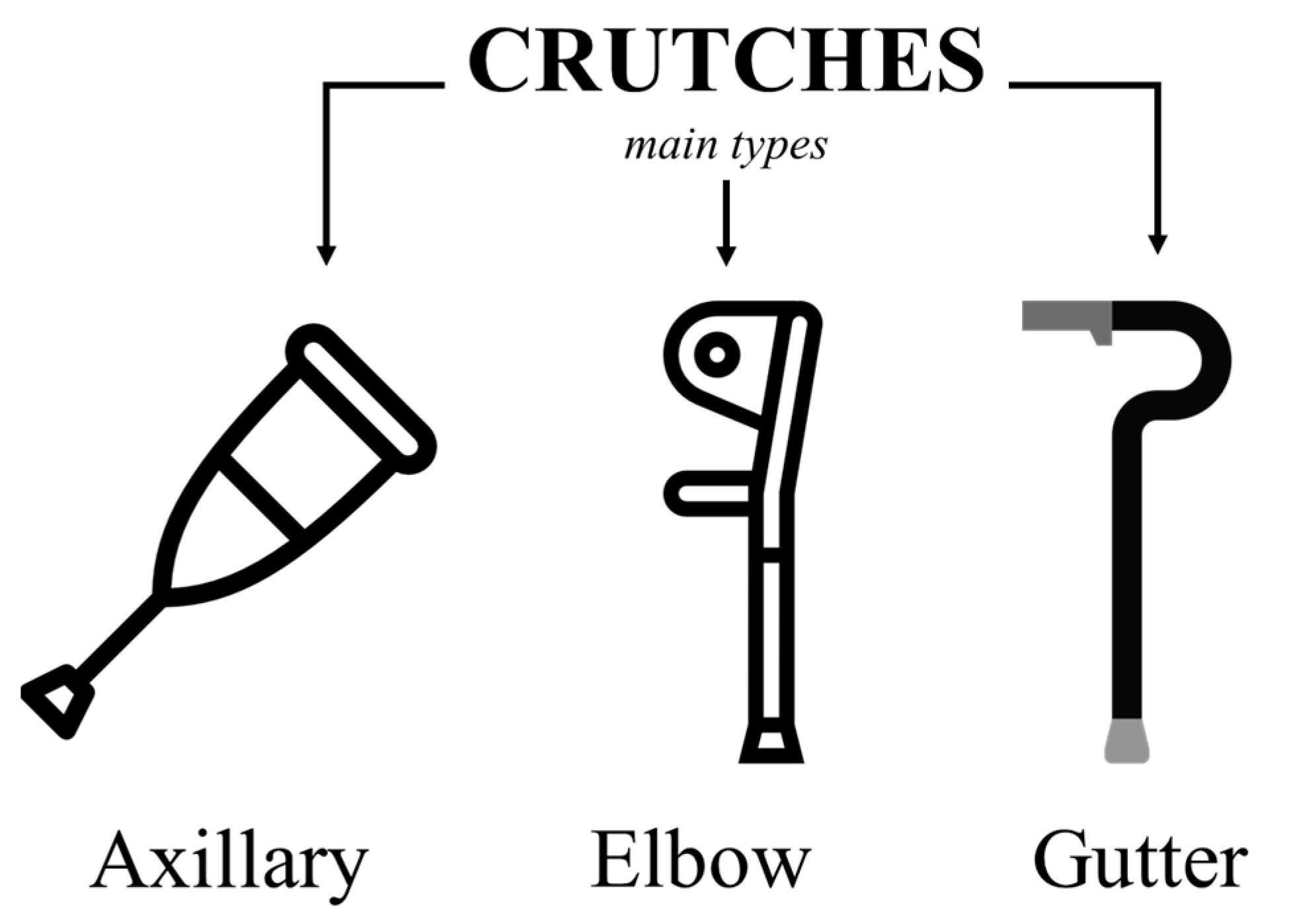
1.1. Background
1.2. Related Work
1.3. Motivation
- Instrumented crutches can provide continuous, real-time monitoring of the patient’s mobility and gait pattern, enabling the objectification of the rate of progression of the rehabilitation for each individual patient.
- Instrumented crutches can collect and transmit data to smartphones or other mobile devices. The computational capacity of modern devices enables real-time applications/feedback and advanced reporting functions for both therapists and patients.
- Instrumented crutches in an mHealth scenario can improve the communication between the patient and the therapist, enabling remote monitoring and teleconsultation. Telerehabilitation applications can be important for patients living in underserved or remote areas. They would improve access to rehabilitation services and reduce the healthcare system’s burden.
- Through smart biofeedback applications and personalized reporting functions, instrumented crutches can empower patients and allow them to take a more active role in their rehabilitation program.
- To develop a set of instrumented crutches suitable for mobile health applications. Expected outcomes are orientation angles and applied loads.
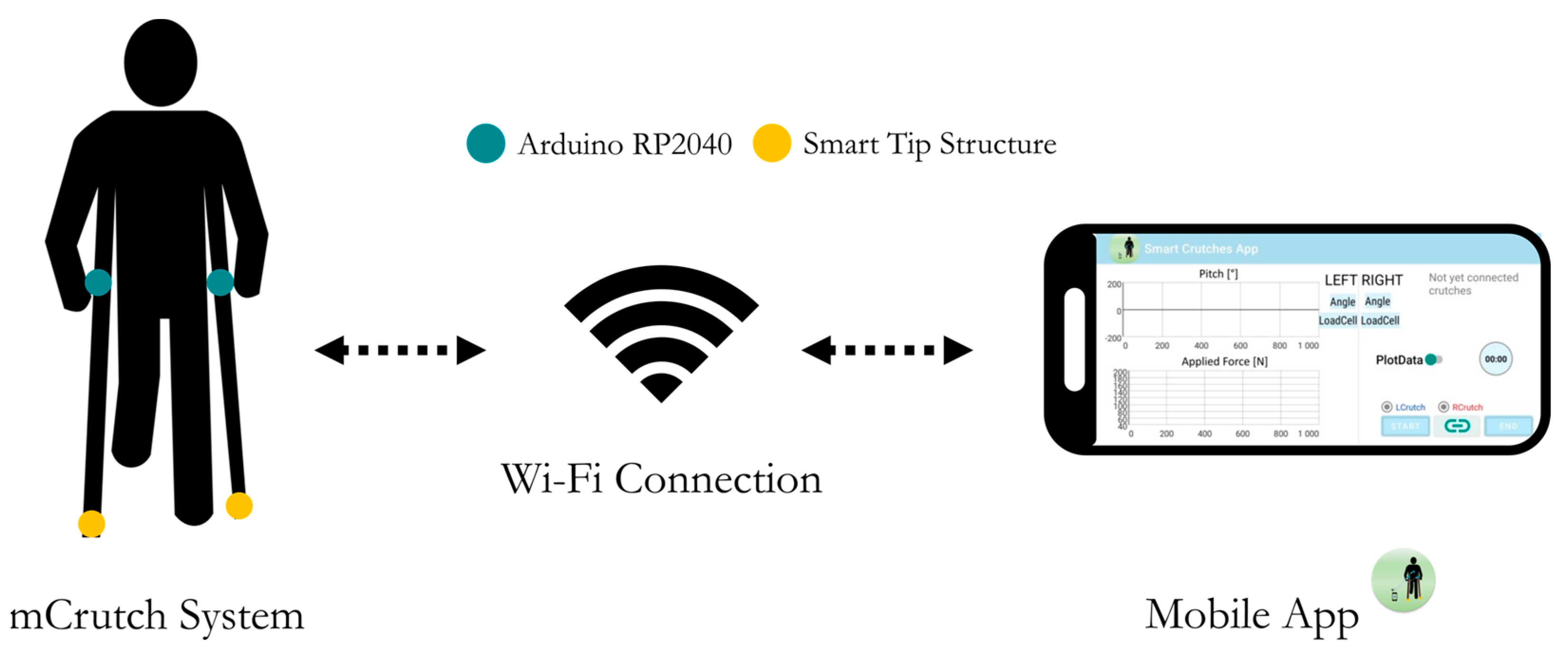
- To develop a smartphone app, mCrutch, for the management of the instrumented crutches and for enabling real-time applications.
- To verify the accuracy of the estimate for the orientation angles and the applied loads.
- To keep manufacturing costs in line with those of mass-market technologies.
2. Materials and Methods
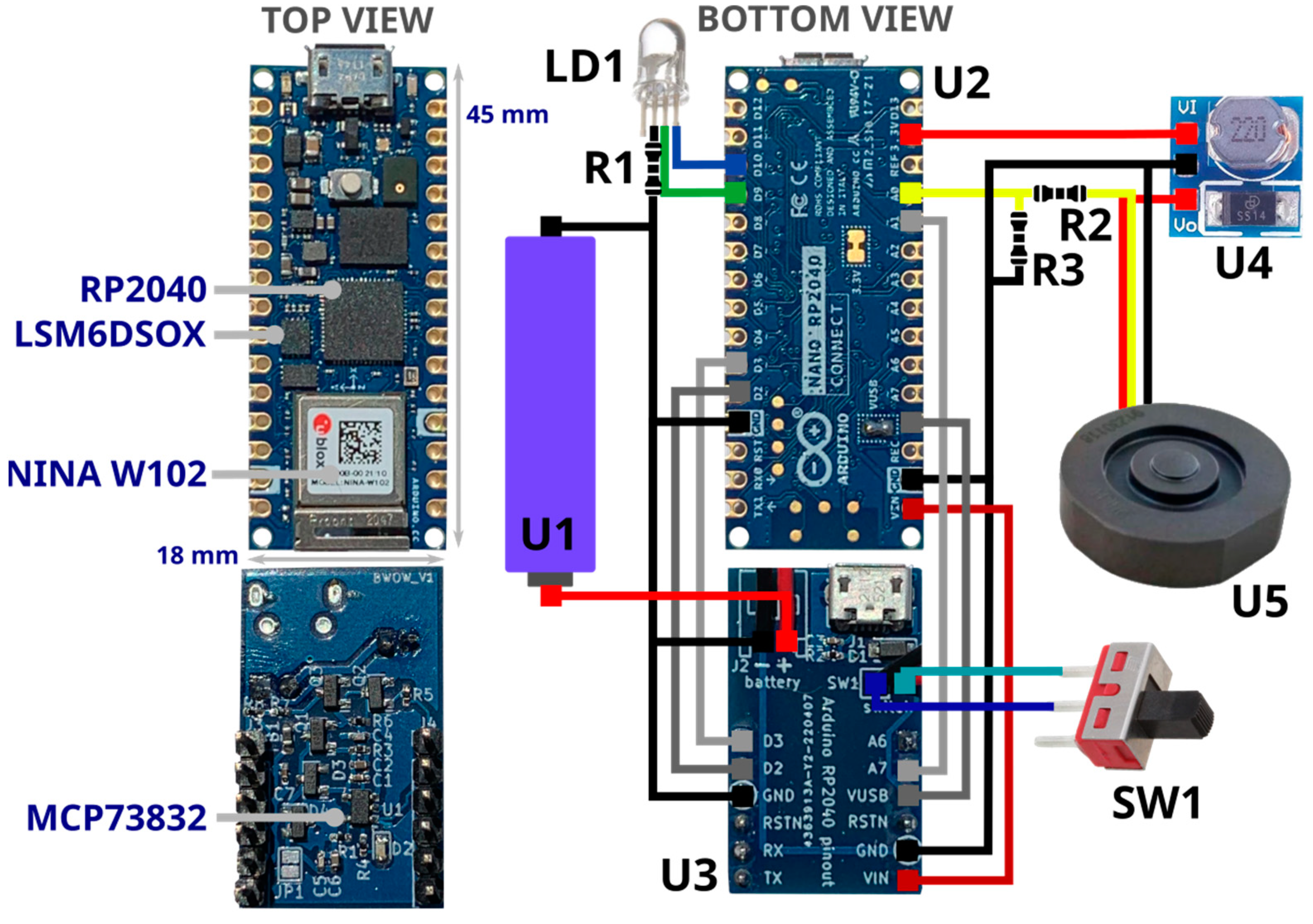
2.1. Electronic Components
- U1—Power supply: Li-Ion battery RS-ICR14500 [42], 3.7 V at 820 mAh.
- U2—Processing, data acquisition and wireless communication management: Raspberry Pi RP2040 MCU [43], a dual-core 32-bit ARM Cortex operating at a frequency of up to 133 MHz, 264 KB on-chip SRAM, up to 16 MB off-chip Flash and various digital and analog peripherals (SPI, I2C, UART, ADC, etc.).
- U2—Wireless communication: U-blox Nina W102 [44], Bluetooth V4.2, and WiFi 802.11 b/g/n module.
- U2—IMU: LSM6DSOX [45], STMicroelectronics micro electro mechanical system (MEMS) sensor, which embeds a three-axial accelerometer and three-axial gyroscope (6-axis IMU) with a full-scale acceleration range up to ±16 g and a maximum angular rate of ±2000 dps. It is used to measure linear acceleration and angular velocity of the crutch for estimating its orientation.
- U3—Li-Ion on-board battery charger: MCP73832 [46], Microchip 500 mA linear charger management controller for single cell Li-Ion/Li-Polymer battery.
- U4—Voltage converter: ANGEEK DC-DC Step-Up, 0.9–5 V to 5 V, operating frequency 150 KHz, conversion efficiency 85%. It boosts Arduino 3.3 V output to 5 V to power the load cell (U5).
- U5—Load cell: uniaxial load cell FX293X-100A-0100-L [47], analog output (0.5–4.5 V) by TE connectivity, with a full-scale range of 500 N, a precision of ±0.25% FS and a round shape (diameter 19.7 mm, height 5.45 mm) used to measure axial force applied on the crutch tip.
- SW1—Slide switch to power ON/OFF the device.
- LD1—RGB LED, signals the system status (green: power on, blue: connected to the host device/smartphone).
- R1—Limits the current to LD1.
- R2, R3—Level shifter to adapt 0.5–4.5 V load cell output to RP2040 MCU ADC channel 0–3.3 V.
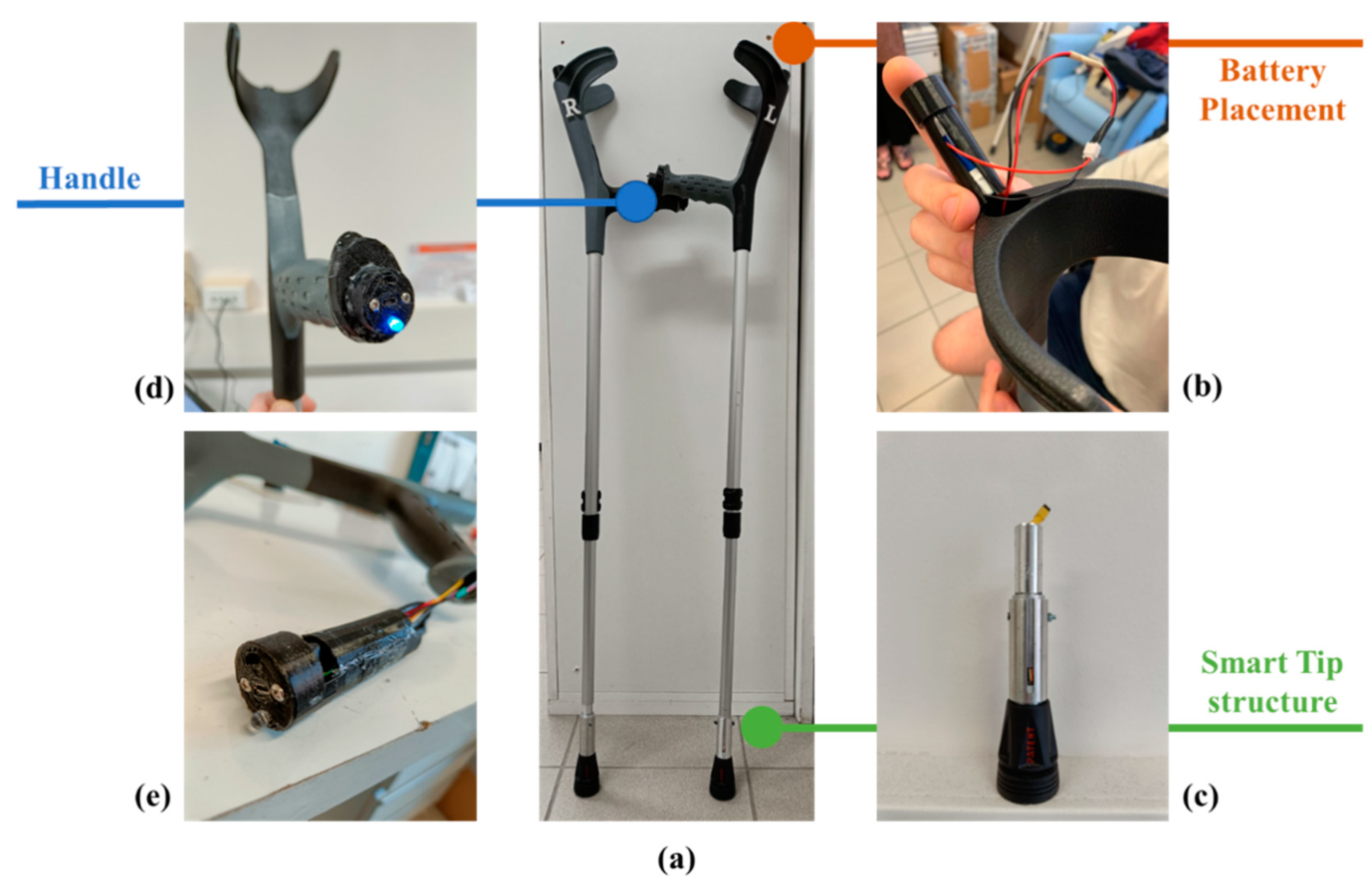
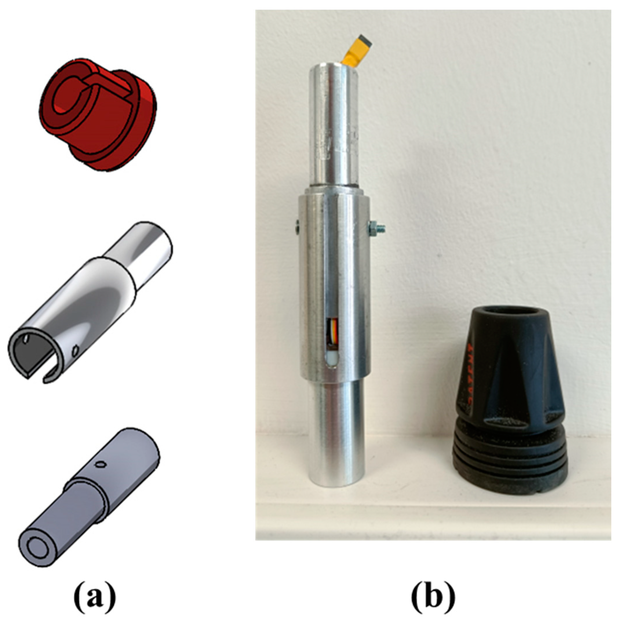
2.2. Smart Tip and Mechanical Structures
- Only the component of force applied along the crutch shaft axis is measured. Other components of force (perpendicular to the shaft) and moments are removed by dedicated low-friction Teflon components mechanically insulating the miniaturized cell.
- When an external force is applied to the crutch, the measured force value reflects the applied load.
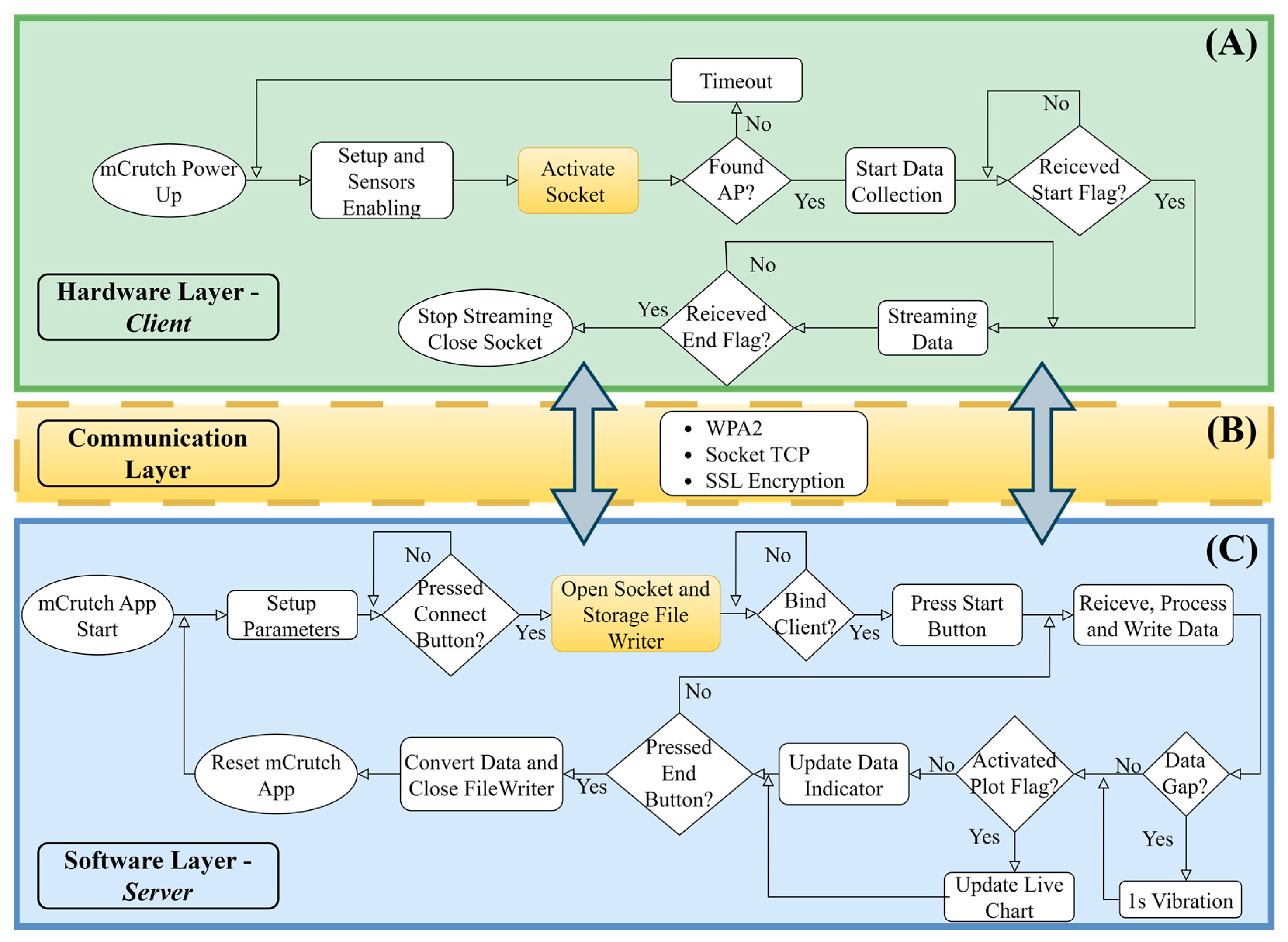
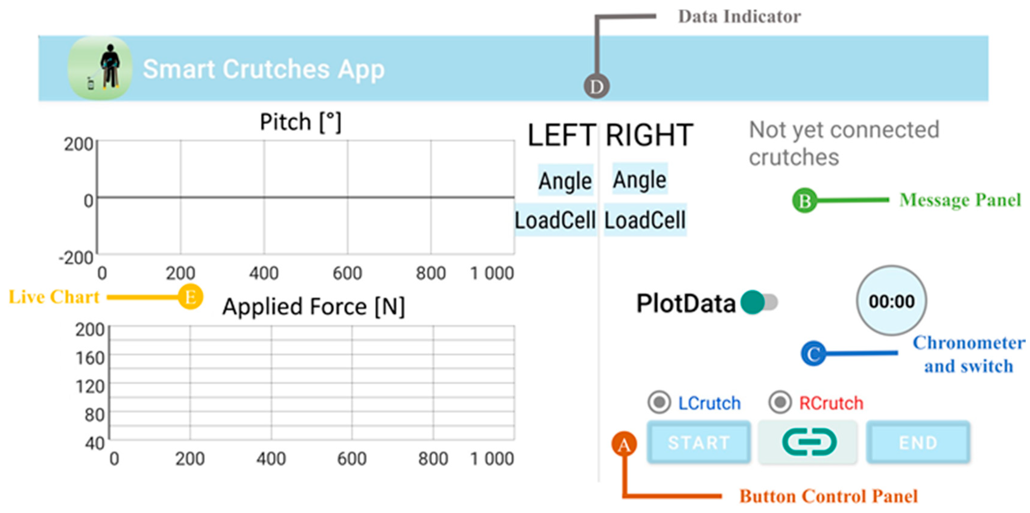
2.3. The mCrutch App
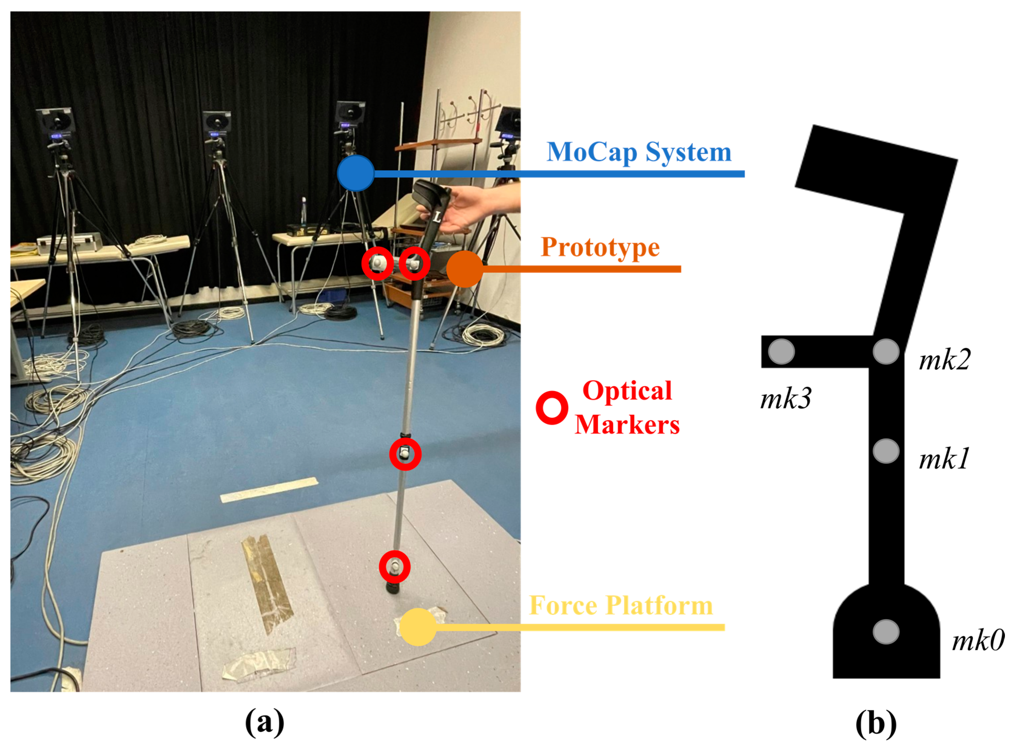
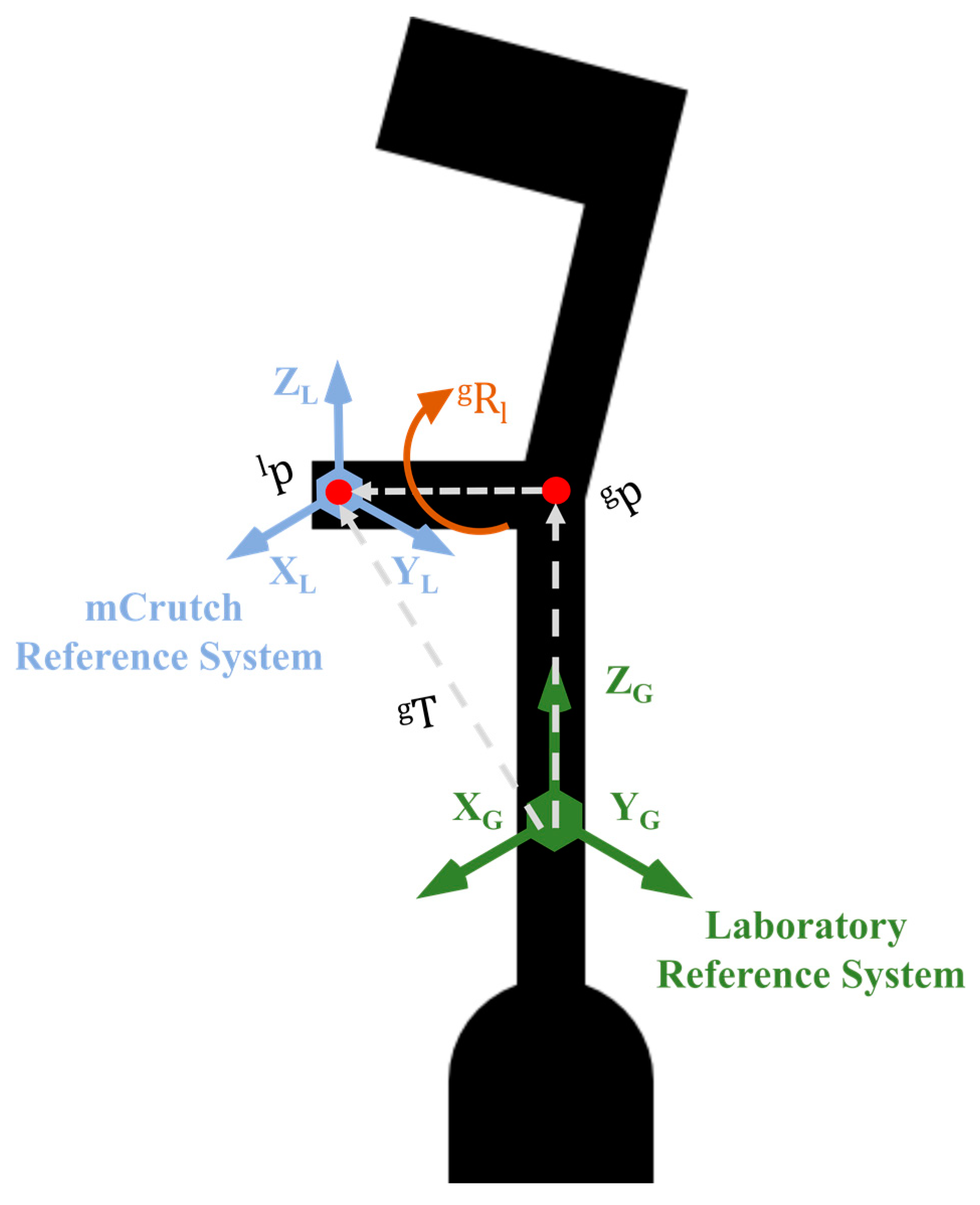
2.4. Calibration Procedure
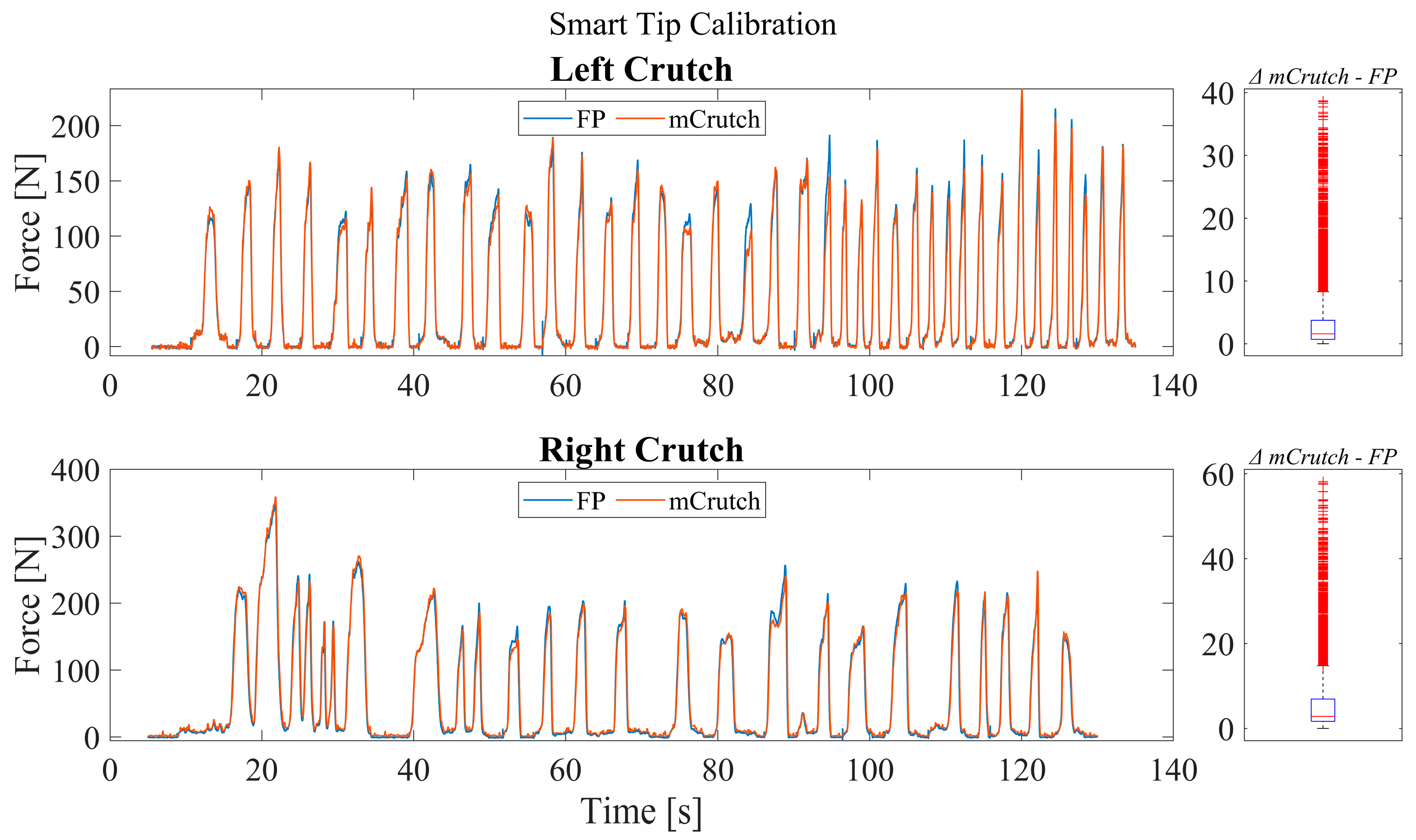
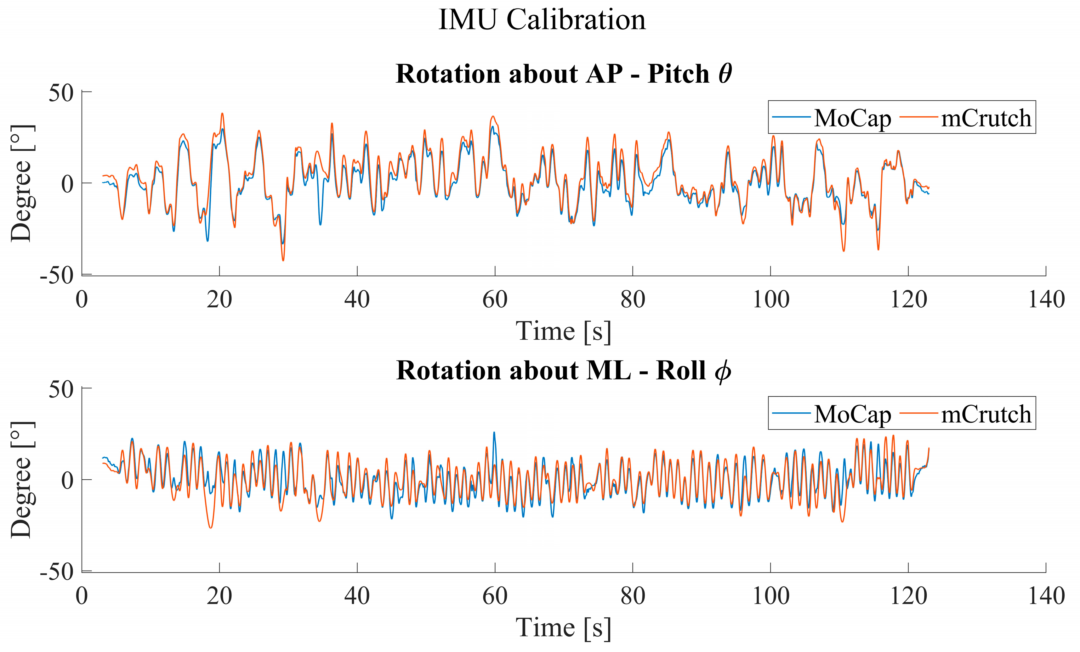
3. Results
4. Discussion
5. Conclusions
Author Contributions
Funding
Institutional Review Board Statement
Informed Consent Statement
Data Availability Statement
Acknowledgments
Conflicts of Interest
Abbreviations
| IMU | Inertial measurement unit |
| Mocap | Motion capture |
| AP | Antero–posterior |
| ML | Medio–lateral |
| RMSE | Root mean square error |
| IDE | Integrated development environment |
| CNS | Central nervous system |
| MCU | Microcontroller unit |
| FP | Force platform |
| SVD | Singular value decomposition |
References
- Culmer, P.R.; Brooks, P.C.; Strauss, D.N.; Ross, D.H.; Levesley, M.C.; O’Connor, R.J.; Bhakta, B.B. An Instrumented Walking Aid to Assess and Retrain Gait. IEEE/ASME Trans. Mechatron. 2014, 19, 141–148. [Google Scholar] [CrossRef]
- Iezzoni, L.I.; McCarthy, E.P.; Davis, R.B.; Siebens, H. Mobility impairments and use of screening and preventive services. Am. J. Public Health 2000, 90, 955–961. [Google Scholar] [CrossRef] [PubMed]
- Demir, Y.P.; Yildirim, S.A. Different walk aids on gait parameters and kinematic analysis of the pelvis in patients with Adult Neuromuscular Disease. Neurosci. J. 2019, 24, 36–44. [Google Scholar] [CrossRef]
- Lloyd-Jones, D.; Adams, R.; Carnethon, M.; De Simone, G.; Ferguson, T.B.; Flegal, K.; Ford, E.; Furie, K.; Go, A.; Greenlund, K.; et al. Heart disease and stroke statistics—2009 update: A report from the American Heart Association Statistics Committee and Stroke Statistics Subcommittee. Circulation 2009, 119, e21–e181. [Google Scholar] [CrossRef] [PubMed]
- Bertrand, K.; Raymond, M.-H.; Miller, W.C.; Martin Ginis, K.A.; Demers, L. Walking Aids for Enabling Activity and Participation: A Systematic Review. Am. J. Phys. Med. Rehabil. 2017, 96, 894–903. [Google Scholar] [CrossRef] [PubMed]
- Haye, H.S.; Kang, T.; LaPlante, M.P. Mobility Device Use in the United States; Disability Statistics Report 14; National Institute on Disability and Rehabilitation Research, U.S. Department of Education: Washington, DC, USA, 2000. [Google Scholar]
- Rasouli, F.; Reed, K.B. Walking assistance using crutches: A state of the art review. J. Biomech. 2020, 98, 109489. [Google Scholar] [CrossRef]
- Satariano, W.A.; Guralnik, J.M.; Jackson, R.J.; Marottoli, R.A.; Phelan, E.A.; Prohaska, T.R. Mobility and Aging: New Directions for Public Health Action. Am. J. Public Health 2012, 102, 1508–1515. [Google Scholar] [CrossRef]
- Word Health Organization. Ageing and Health. Available online: https://www.who.int/news-room/fact-sheets/detail/ageing-and-health (accessed on 20 February 2023).
- Haubert, L.L.; Gutierrez, D.D.; Newsam, C.J.; Gronley, J.A.K.; Mulroy, S.J.; Perry, J. A Comparison of Shoulder Joint Forces during Ambulation with Crutches Versus a Walker in Persons with Incomplete Spinal Cord Injury. Arch. Phys. Med. Rehabil. 2006, 87, 63–70. [Google Scholar] [CrossRef]
- Deaver, G. Posture and its relation to mental and physical health. Res. Q. Am. Phys. Educ. Assoc. 1933, 4, 221–228. [Google Scholar] [CrossRef]
- Chung, T.Y. Lower Limb Orthoses. In Braddom’s Rehabilitation Care: A Clinical Handbook; Elsevier: Amsterdam, The Netherlands, 2018; pp. 75–84.e3. [Google Scholar] [CrossRef]
- Physiopedia. Available online: https://www.physio-pedia.com/Crutches (accessed on 20 February 2023).
- Yap, W.; Hairodin, Z.; Kwek, E. Axillary versus forearm crutches: A prospective cohort comparing which is superior for 3-point crutch gait. Malays. Orthop. J. 2021, 15, 36–42. [Google Scholar] [CrossRef]
- Van Hook, F.W.; Demonbreun, D.; Weiss, B.D. Ambulatory devices for chronic gait disorders in the elderly. Am. Fam. Physician 2003, 67, 1717–1724. [Google Scholar] [PubMed]
- Gardiner, D.M. The Principles Of Exercise Therapy, 4th ed.; CBS Publishers & Distributors: Delhi, India, 2004. [Google Scholar]
- Hurkmans, H.L.; Bussmann, J.B.; Benda, E. Validity and Interobserver Reliability of Visual Observation to Assess Partial Weight-Bearing. Arch. Phys. Med. Rehabil. 2009, 90, 309–313. [Google Scholar] [CrossRef] [PubMed]
- Viehweger, E.; Pfund, L.Z.; Hélix, M.; Rohon, M.A.; Jacquemier, M.; Scavarda, D.; Jouve, J.L.; Bollini, G.; Loundou, A.; Simeoni, M.C. Influence of clinical and gait analysis experience on reliability of observational gait analysis (Edinburgh Gait Score Reliability). Ann. Phys. Rehabil. Med. 2010, 53, 535–546. [Google Scholar] [CrossRef] [PubMed]
- Zhang, X.; Xiang, Z.; Lin, Q.; Zhou, Q. The design and development of a lower limbs rehabilitation exoskeleton suit. 2013 ICME Int. Conf. Complex Med. Eng. 2013, 307–312. [Google Scholar] [CrossRef]
- Merrett, G.V.; Peters, C.; Hallet, G.; White, N.M. An instrumented crutch for monitoring patients’ weight distribution during orthopaedic rehabilitation. Procedia Chem. 2009, 1, 714–717. [Google Scholar] [CrossRef]
- Sardini, E.; Serpelloni, M.; Lancini, M.; Pasinetti, S. Wireless Instrumented Crutches for Force and Tilt Monitoring in Lower Limb Rehabilitation. Procedia Eng. 2014, 87, 348–351. [Google Scholar] [CrossRef]
- Tamburella, F.; Lorusso, M.; Tagliamonte, N.L.; Bentivoglio, F.; Bigioni, A.; Pisotta, I.; Lancini, M.; Pasinetti, S.; Ghidelli, M.; Masciullo, M.; et al. Load Auditory Feedback Boosts Crutch Usage in Subjects with Central Nervous System Lesions: A Pilot Study. Front. Neurol. 2021, 12, 700472. [Google Scholar] [CrossRef]
- Chamorro Moriana, G.; Roldán, J.R.; Rejano, J.J.J.; Martínez, R.C.; Serrano, C.S. Design and validation of GCH System 1.0 which measures the weight-bearing exerted on forearm crutches during aided gait. Gait Posture 2013, 37, 564–569. [Google Scholar] [CrossRef]
- Chamorro-Moriana, G.; Sevillano, J.L.; Ridao-Fernández, C. A Compact Forearm Crutch Based on Force Sensors for Aided Gait: Reliability and Validity. Sensors 2016, 16, 925. [Google Scholar] [CrossRef]
- Chamorro-Moriana, G.; Sevillano, J.L.; Perez-Cabezas, V. Versatile GCH Control Software for Correction of Loads Applied to Forearm Crutches during Gait Recovery through Technological Feedback: Development and Implementation Study. J. Med. Internet Res. 2021, 23, e27602. [Google Scholar] [CrossRef]
- Narváez, M.; Aranda, J. Gait Patterns Monitoring Using Instrumented Forearm Crutches BT—Computers Helping People with Special Needs. In Proceedings of the 17th International Conference, ICCHP 2020, Lecco, Italy, 9–11 September 2020; pp. 402–410. [Google Scholar] [CrossRef]
- Brull, A.; Zubizarreta, A.; Cabanes, I.; Rodriguez-Larrad, A. Sensorized Tip for Monitoring People with Multiple Sclerosis that Require Assistive Devices for Walking. Sensors 2020, 20, 4329. [Google Scholar] [CrossRef] [PubMed]
- Brull, A.; Zubizarreta, A.; Cabanes, I.; Torres-Unda, J.; Rodriguez-Larrad, A. A Smart Crutch Tip for Monitoring the Activities of Daily Living Based on a Novel Neural-Network Intelligent Classifier. In Proceedings of the BT—15th International Conference on Soft Computing Models in Industrial and Environmental Applications (SOCO 2020), Burgos, Spain, 16–18 September 2021; pp. 113–122. [Google Scholar] [CrossRef]
- Sesar, I.; Zubizarreta, A.; Cabanes, I.; Portillo, E.; Torres-Unda, J.; Rodriguez-Larrad, A. Instrumented Crutch Tip for Monitoring Force and Crutch Pitch Angle. Sensors 2019, 19, 2944. [Google Scholar] [CrossRef] [PubMed]
- Yang, W.; Zhang, J.; Zhang, S.; Yang, C. Lower Limb Exoskeleton Gait Planning Based on Crutch and Human-Machine Foot Combined Center of Pressure. Sensors 2020, 20, 7216. [Google Scholar] [CrossRef]
- Jung, J.; Jang, I.; Riener, R.; Park, H. Walking intent detection algorithm for paraplegic patients using a robotic exoskeleton walking assistant with crutches. Int. J. Control Autom. Syst. 2012, 10, 954–962. [Google Scholar] [CrossRef]
- Corzani, M. mHealth Apps for Older Adults and Persons with Parkinson’s Disease. In BT—Internet of Things for Human-Centered Design: Application to Elderly Healthcare; Scataglini, S., Imbesi, S., Marques, G., Eds.; Springer: Singapore, 2022; pp. 233–259. [Google Scholar]
- Giansanti, D. The Role of the mHealth in the Fight against the Covid-19: Successes and Failures. Healthcare 2021, 9, 58. [Google Scholar] [CrossRef] [PubMed]
- Iyengar, K.; Upadhyaya, G.K.; Vaishya, R.; Jain, V. COVID-19 and applications of smartphone technology in the current pandemic. Diabetes Metab. Syndr. Clin. Res. Rev. 2020, 14, 733–737. [Google Scholar] [CrossRef]
- Ming, L.C.; Untong, N.; Aliudin, N.A.; Osili, N.; Kifli, N.; Tan, C.S.; Goh, K.W.; Ng, P.W.; Al-Worafi, Y.M.; Lee, K.S.; et al. Mobile Health Apps on COVID-19 Launched in the Early Days of the Pandemic: Content Analysis and Review. JMIR Mhealth Uhealth 2020, 8, e19796. [Google Scholar] [CrossRef]
- Sun, S.; Folarin, A.A.; Ranjan, Y.; Rashid, Z.; Conde, P.; Stewart, C.; Cummins, N.; Matcham, F.; Dalla Costa, G.; Simblett, S.; et al. Using Smartphones and Wearable Devices to Monitor Behavioral Changes During COVID-19. J Med. Internet Res. 2020, 22, e19992. [Google Scholar] [CrossRef]
- Taha, A.R.; Shehadeh, M.; Alshehhi, A.; Altamimi, T.; Housser, E.; Simsekler, M.C.E.; Alfalasi, B.; Al Memari, S.; Al Hosani, F.; Al Zaabi, Y.; et al. The integration of mHealth technologies in telemedicine during the COVID-19 era: A cross-sectional study. PLoS ONE 2022, 17, e0264436. [Google Scholar] [CrossRef]
- Prieto-Moreno, R.; Estévez-López, F.; Molina-Garcia, P.; Mora-Traverso, M.; Deschamps, K.; Claeys, K.; de Buyser, J.; Ariza-Vega, P. ActiveHip+: A feasible mHealth system for the recovery of older adults after hip surgery during the COVID-19 pandemic. Digit. Health 2022, 8, 20552076221139696. [Google Scholar] [CrossRef]
- Adans-Dester, C.P.; Bamberg, S.; Bertacchi, F.P.; Caulfield, B.; Chappie, K.; Demarchi, D.; Erb, M.K.; Estrada, J.; Fabara, E.E.; Freni, M.; et al. Can mHealth Technology Help Mitigate the Effects of the COVID-19 Pandemic? IEEE Open J. Eng. Med. Biol. 2020, 1, 243–248. [Google Scholar] [CrossRef] [PubMed]
- Ghani, Z.; Jarl, J.; Sanmartin Berglund, J.; Andersson, M.; Anderberg, P. The Cost-Effectiveness of Mobile Health (mHealth) Interventions for Older Adults: Systematic Review. Int. J. Environ. Res. Public Health 2020, 17, 5290. [Google Scholar] [CrossRef] [PubMed]
- Arduino Arduino RP2040 Connect Manual. Available online: https://docs.arduino.cc/static/8d277a404eb5cb8f67d3317e3ae711b0/ABX00053-datasheet.pdf (accessed on 20 February 2023).
- RS RS Pro Rechargeable Lithium Ion Battery. Available online: https://docs.rs-online.com/cd82/A700000009044205.pdf. (accessed on 20 February 2023).
- Raspberry PI RP 2040 Datasheet. Available online: https://datasheets.raspberrypi.com/rp2040/rp2040-datasheet.pdf (accessed on 20 February 2023).
- U-blox NINA-W10 Series Datasheet. Available online: https://content.u-blox.com/sites/default/files/NINA-W10_DataSheet_UBX-17065507.pdf. (accessed on 20 February 2023).
- STMicroelectronics LSM6DSOX IMU Datasheet. Available online: https://www.st.com/resource/en/datasheet/lsm6dsox.pdf (accessed on 20 February 2023).
- Microchip Single Cell, Li-Ion/Li-Polymer Charge Management Controller Datasheet. Available online: https://ww1.microchip.com/downloads/aemDocuments/documents/APID/ProductDocuments/DataSheets/MCP73831-Family-Data-Sheet-DS20001984H.pdf (accessed on 20 February 2023).
- TE Connectivity Load Cell FX293X-100A-0100-L Product Page. Available online: https://www.te.com/usa-en/product-20009605-15.html (accessed on 20 February 2023).
- Madgwick, S.O.H.; Harrison, A.J.L.; Vaidyanathan, R. Estimation of IMU and MARG orientation using a gradient descent algorithm. In Proceedings of the IEEE International Conference on Rehabilitation Robotics, Zurich, Switzerland, 29 June–1 July 2011; pp. 1–7. [Google Scholar]
- BTS Bioengineering. Available online: https://www.btsbioengineering.com/products/smart-dx-evo/ (accessed on 20 February 2023).
- Valevicius, A.M.; Jun, P.Y.; Hebert, J.S.; Vette, A.H. Use of optical motion capture for the analysis of normative upper body kinematics during functional upper limb tasks: A systematic review. J. Electromyogr. Kinesiol. 2018, 40, 1–15. [Google Scholar] [CrossRef] [PubMed]
- Söderkvist, I.; Wedin, P.Å. Determining the movements of the skeleton using well-configured markers. J. Biomech. 1993, 26, 1473–1477. [Google Scholar] [CrossRef] [PubMed]
- Schmitt, A.C.; Baudendistel, S.T.; Lipat, A.L.; White, T.A.; Raffegeau, T.E.; Hass, C.J. Walking indoors, outdoors, and on a treadmill: Gait differences in healthy young and older adults. Gait Posture 2021, 90, 468–474. [Google Scholar] [CrossRef]
- Rubin, G.; Monder, O.; Zohar, R.; Oster, A.; Konra, O.; Rozen, N. Toe-Touch Weight Bearing: Myth or Reality? Orthopedics 2010, 33, 729. [Google Scholar] [CrossRef]
- Flood, D.K. Proper Fitting and Use of Crutches. Phys. Sportsmed. 1983, 11, 75–78. [Google Scholar] [CrossRef]
- Takayuki, N.; Hiroshi, K.; Arizono, H.; Hikaru, C.; Naoki, C.; Takaaki, O.; Chikamune, W. Analysis of crutch position in the horizontal plane to confirm the stabilityof the axillary pad for safe double-crutch walking. J. Phys. Ther. Sci. 2016, 28, 1438–1442. [Google Scholar] [CrossRef]
- Honeywell Model 13 Series. Available online: https://sps.honeywell.com/us/en/products/advanced-sensing-technologies/industrial-sensing/industrial-test-and-measurement/load-cells/subminiature-load-cells/model-13-series (accessed on 28 March 2023).
- Xsens MTi-3. Available online: https://www.xsens.com/hubfs/Downloads/Leaflets/MTi-3.pdf (accessed on 28 March 2023).
- MuRata SCC2130-D08. Available online: https://www.murata.com/en-eu/products/productdetail?partno=SCC2130-D08 (accessed on 28 March 2023).
- Zihajehzadeh, S.; Yoon, P.K.; Park, E.J. A magnetometer-free indoor human localization based on loosely coupled IMU/UWB fusion. In Proceedings of the 2015 37th Annual International Conference of the IEEE Engineering in Medicine and Biology Society (EMBC), Milan, Italy, 25–29 August 2015; pp. 3141–3144. [Google Scholar]
- Corrales, J.A.; Candelas, F.A.; Torres, F. Sensor data integration for indoor human tracking. Rob. Auton. Syst. 2010, 58, 931–939. [Google Scholar] [CrossRef]


| Features | Description |
|---|---|
| Computational power | Dual-core 32-bit ARM up to 133 MHz, 264 KB SRAM |
| Connectivity | Wi-Fi 802.11b/g/n |
| Orientation estimation | 6-axis IMU (accelerometer + gyroscope) |
| Applied force | Load cell full scale: 500 N |
| Power supply | Li-Ion battery, 3.7 V at 820 mAh (charger on-board, up to 500 mAh) |
| LED indicator | Green: power on Blue: connected to smartphone |
Disclaimer/Publisher’s Note: The statements, opinions and data contained in all publications are solely those of the individual author(s) and contributor(s) and not of MDPI and/or the editor(s). MDPI and/or the editor(s) disclaim responsibility for any injury to people or property resulting from any ideas, methods, instructions or products referred to in the content. |
© 2023 by the authors. Licensee MDPI, Basel, Switzerland. This article is an open access article distributed under the terms and conditions of the Creative Commons Attribution (CC BY) license (https://creativecommons.org/licenses/by/4.0/).
Share and Cite
Arcobelli, V.A.; Zauli, M.; Galteri, G.; Cristofolini, L.; Chiari, L.; Cappello, A.; De Marchi, L.; Mellone, S. mCrutch: A Novel m-Health Approach Supporting Continuity of Care. Sensors 2023, 23, 4151. https://doi.org/10.3390/s23084151
Arcobelli VA, Zauli M, Galteri G, Cristofolini L, Chiari L, Cappello A, De Marchi L, Mellone S. mCrutch: A Novel m-Health Approach Supporting Continuity of Care. Sensors. 2023; 23(8):4151. https://doi.org/10.3390/s23084151
Chicago/Turabian StyleArcobelli, Valerio Antonio, Matteo Zauli, Giulia Galteri, Luca Cristofolini, Lorenzo Chiari, Angelo Cappello, Luca De Marchi, and Sabato Mellone. 2023. "mCrutch: A Novel m-Health Approach Supporting Continuity of Care" Sensors 23, no. 8: 4151. https://doi.org/10.3390/s23084151