
Design and Characterization of a Low-Cost and Efficient Torsional Spring for ES-RSEA
 , , and
Abstract
:1. Introduction
1.1. Background
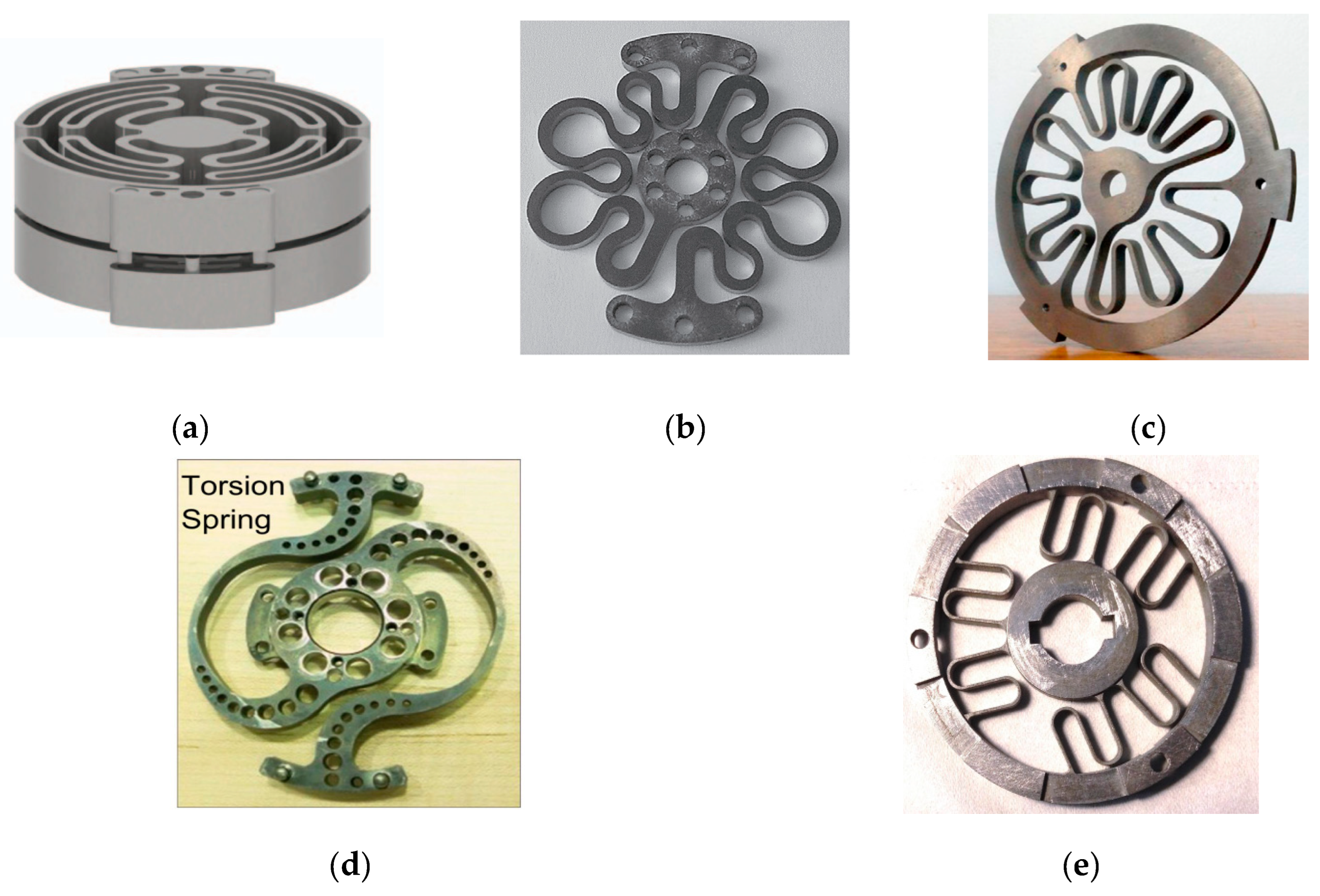
1.2. Torsional Springs for a Rotary Series Elastic Actuator: State of the Art

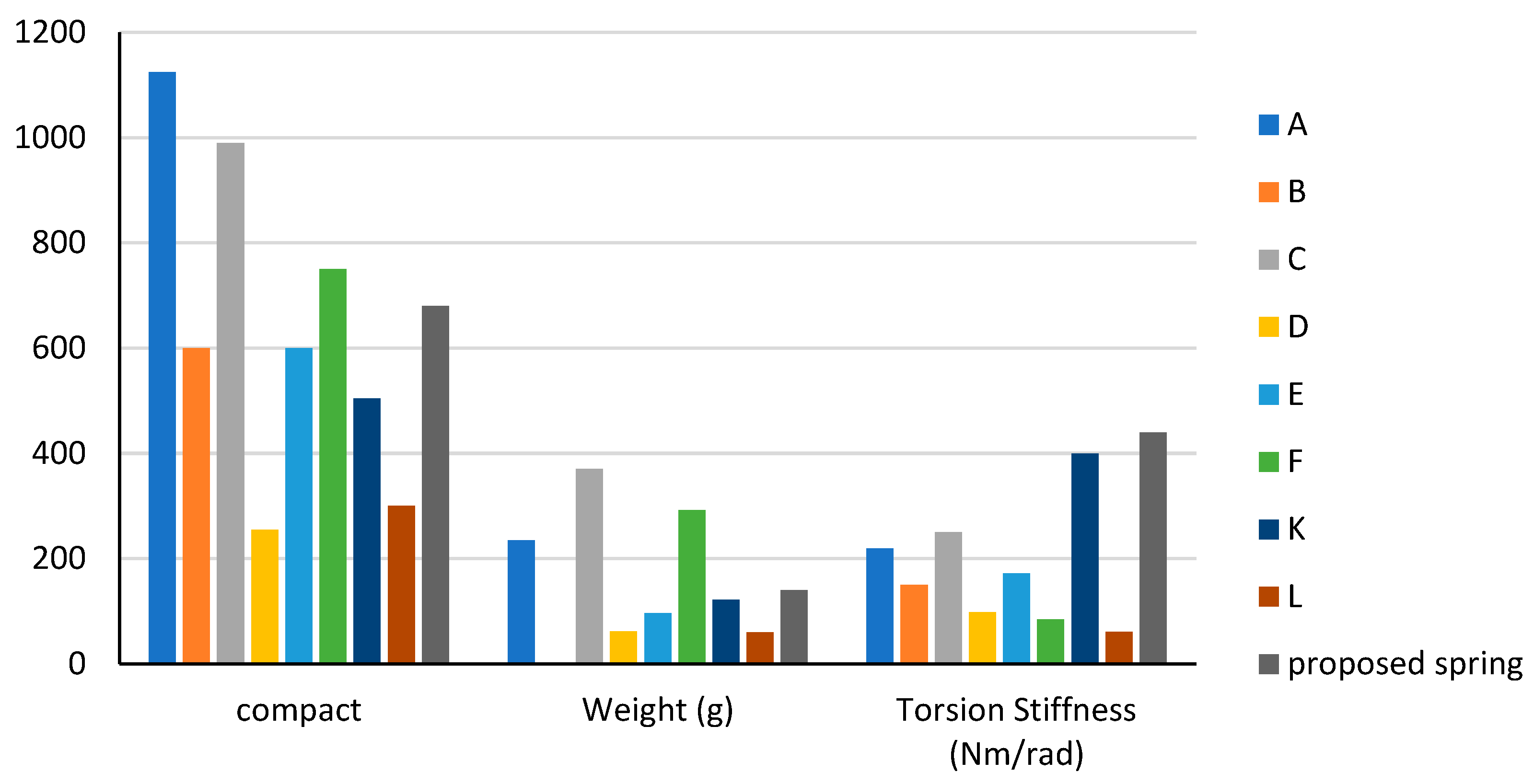
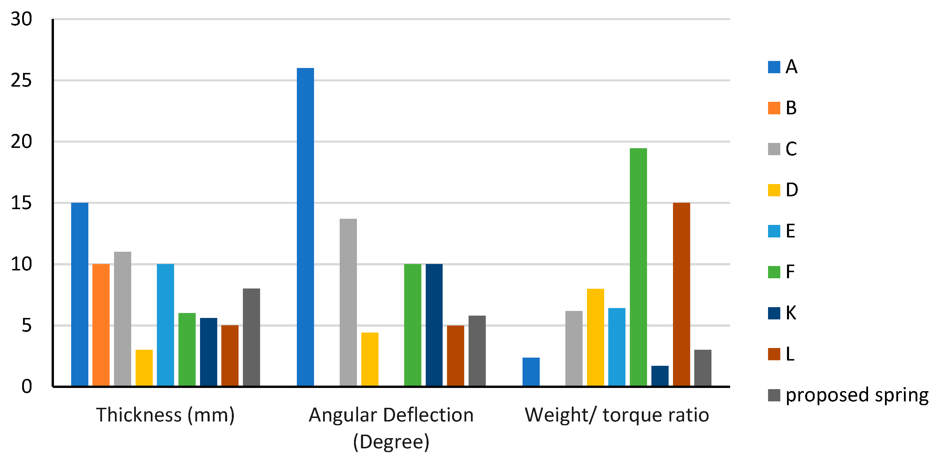
| Spring | Diameter (mm) | Thickness (mm) | Weight (g) | Torque (Nm) | Torsion Stiffness (Nm/rad) | Angular Deflection (Degree) | Material | Weight/Torque Ratio | Application |
|---|---|---|---|---|---|---|---|---|---|
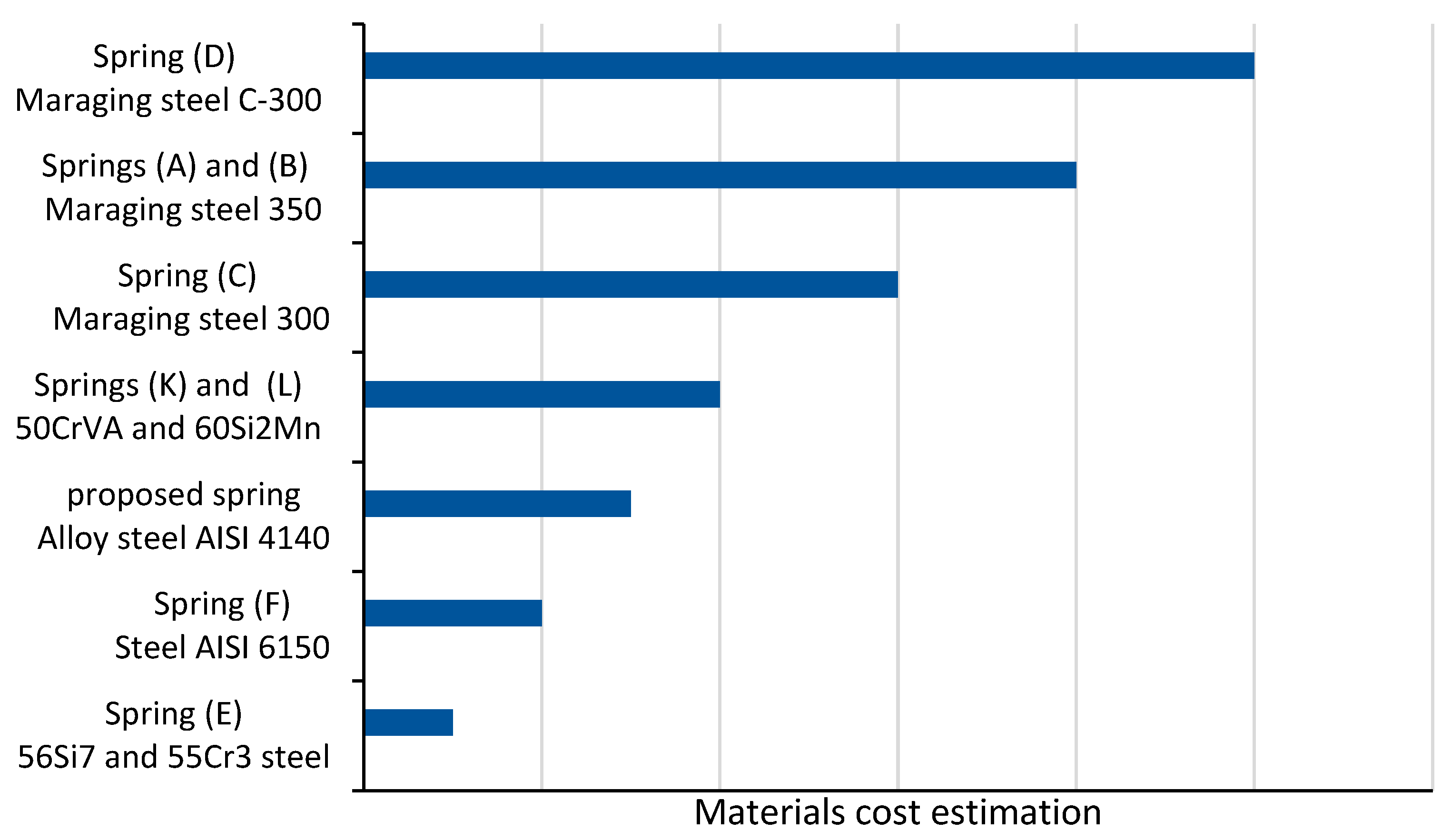
| A [15] | 75 | 15 | 235 | 100 | 219 | 26 | Maraging steel 350 | 2.35 | Gait rehabilitation training (stroke survivors) |
| B [10] | 60 | 10 | Unknown | 50 | 150 | Unknown | Maraging steel 350 | Unknown | Upper limb rehabilitation |
| C [16] | 90 | 11 | 370 | 60 | 250 | 13.7 | Maraging steel 300 | 6.17 | Gait assistance and human augmentation |
| D [7] | 85 | 3 | 61.5 | 7.7 | 98 | 4.4 | Maraging steel C-300 | 7.98 | Gait assistance and human augmentation |
| E [17] | 60 | 10 | 96 | 15 | 172(3) | Unknown | 56Si7 and 55Cr3 steel | 6.4 | Stroke rehabilitation device for motor impairments |
| F [18] | 125 | 6 | 292 | 15 | 84 | 10 | Chromium–Vanadium steel (AISI 6150) | 19.46 | Stroke rehabilitation, gait training |
| K [25,26] | 90 | 5.6 | 121.7 | 70 | 400 | 10 | 50CrVA | 1.7 | Gait assistance and human augmentation |
| L [22,23] | 60 | 5 | 60 | 4 | 60.2 | 4.98 | 60Si2Mn | 15 | Gait assistance exoskeleton |
1.3. Design Objectives of the Proposed Torsional Spring
2. Design Considerations
2.1. Design for Manufacturing (DFM) Approach
2.2. Mechanical Design Considerations
2.3. Selection of Spring Stiffness
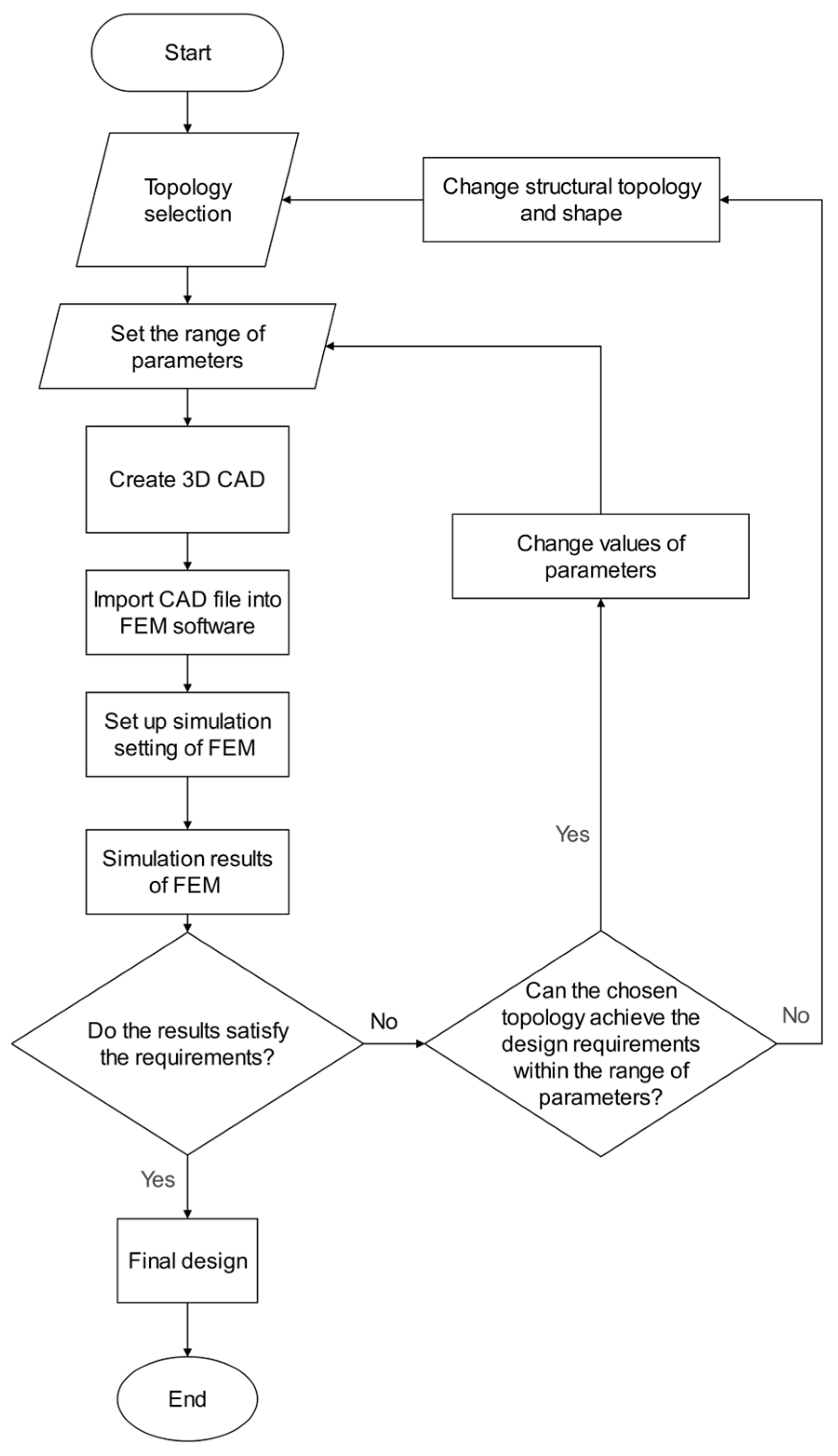
3. Topology Design of Torsion Spring
- Adjust the parameters within the acceptable range for the selected topology [47].
- If the parameter search space for the specified topology has been fully explored, change the structural topology and repeat the process (the topology is discarded after 20 iterations if the design requirements are still unsatisfied).
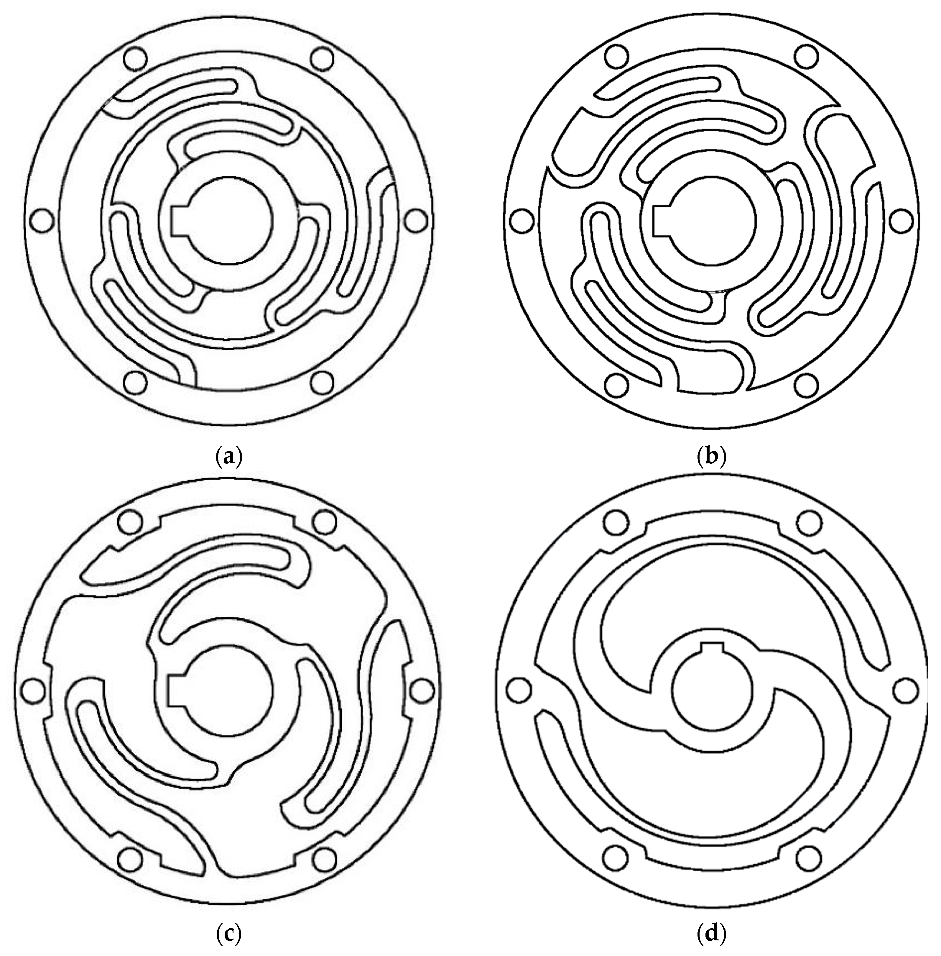
3.1. Selection of the Suitable Topology
- Parameter range values for each topology were determined and applied.
- The parts were modelled in Autodesk Inventor (2020) using parametric CAD.
- The CAD file was imported into ANSYS Workbench (2022 R2, Canonsburg, PE, USA) for FEM-based geometry optimization.
- Design requirements-based simulations were conducted to achieve the desired spring characteristics.
3.2. Schematic Design
3.3. Finite Element Method (FEM) Based Design Approach
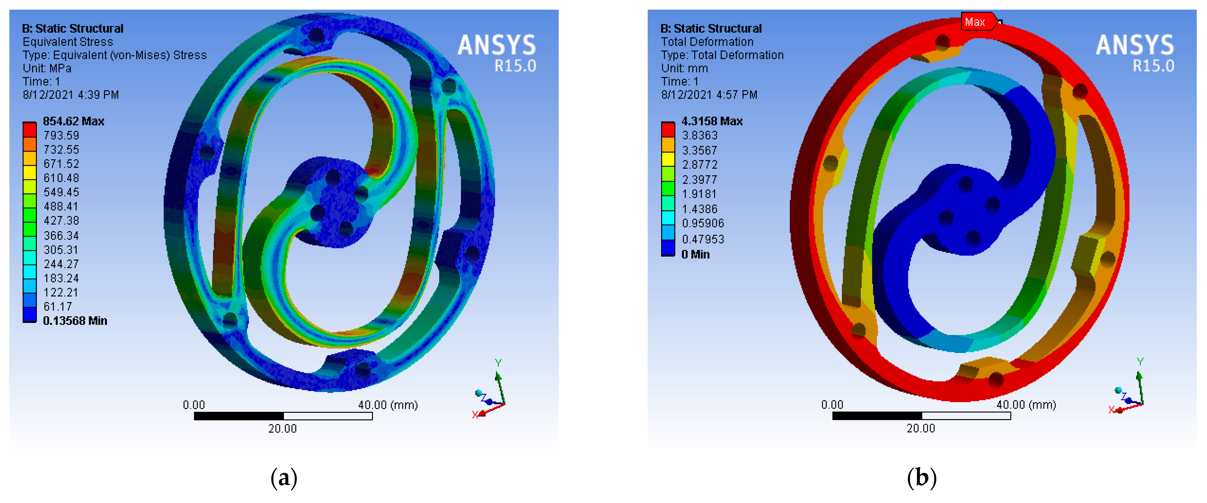
3.4. Design Verification Using FEM
4. Experimental Characterization of Torsion Spring
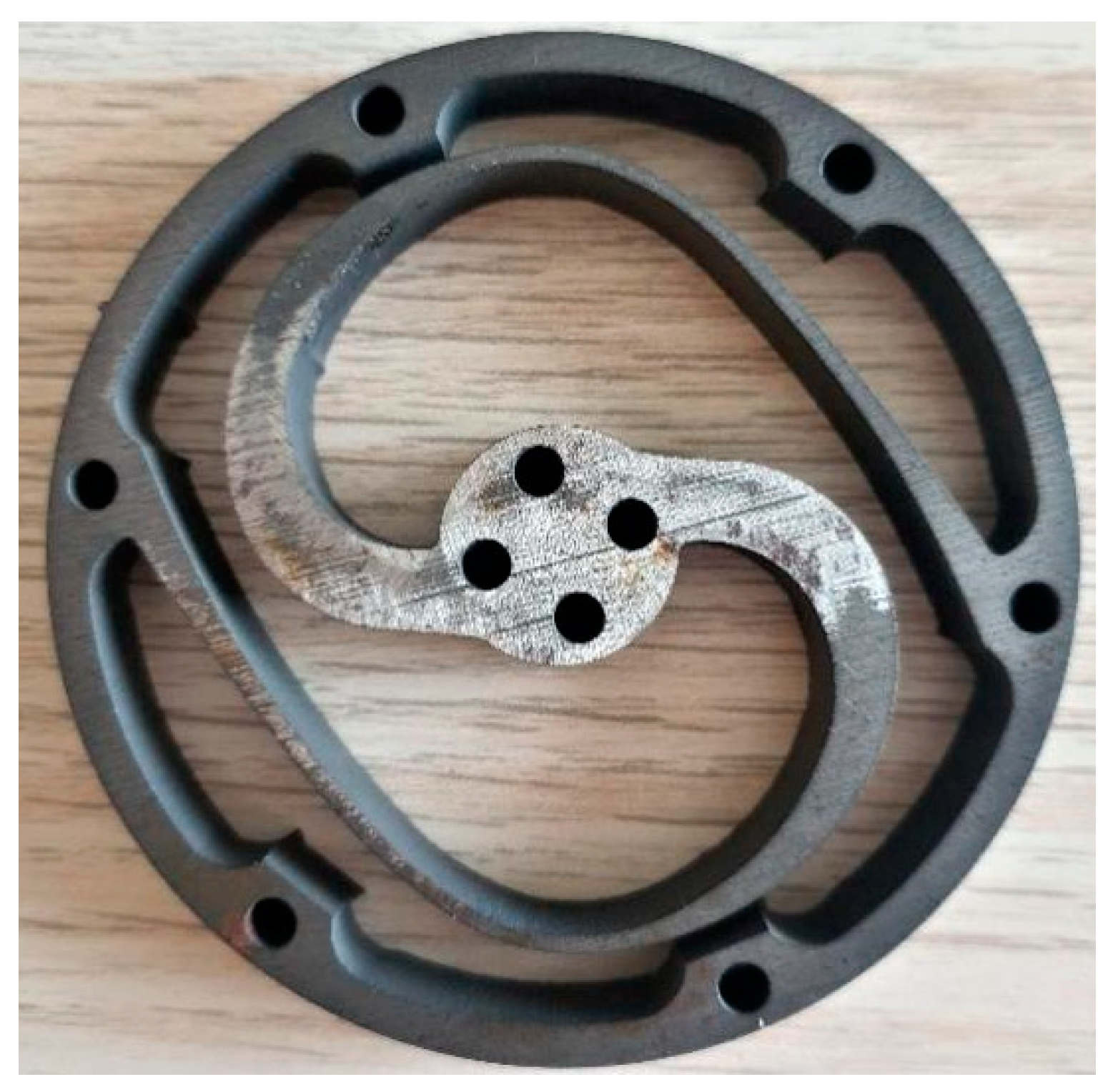
4.1. Manufacturing of the Torsion Spring
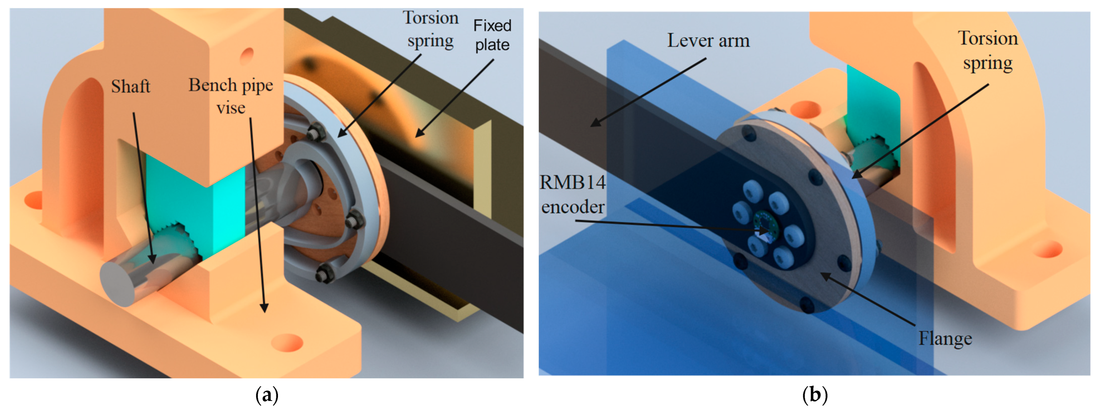
4.2. Test Rig Setup
5. Results and Discussion
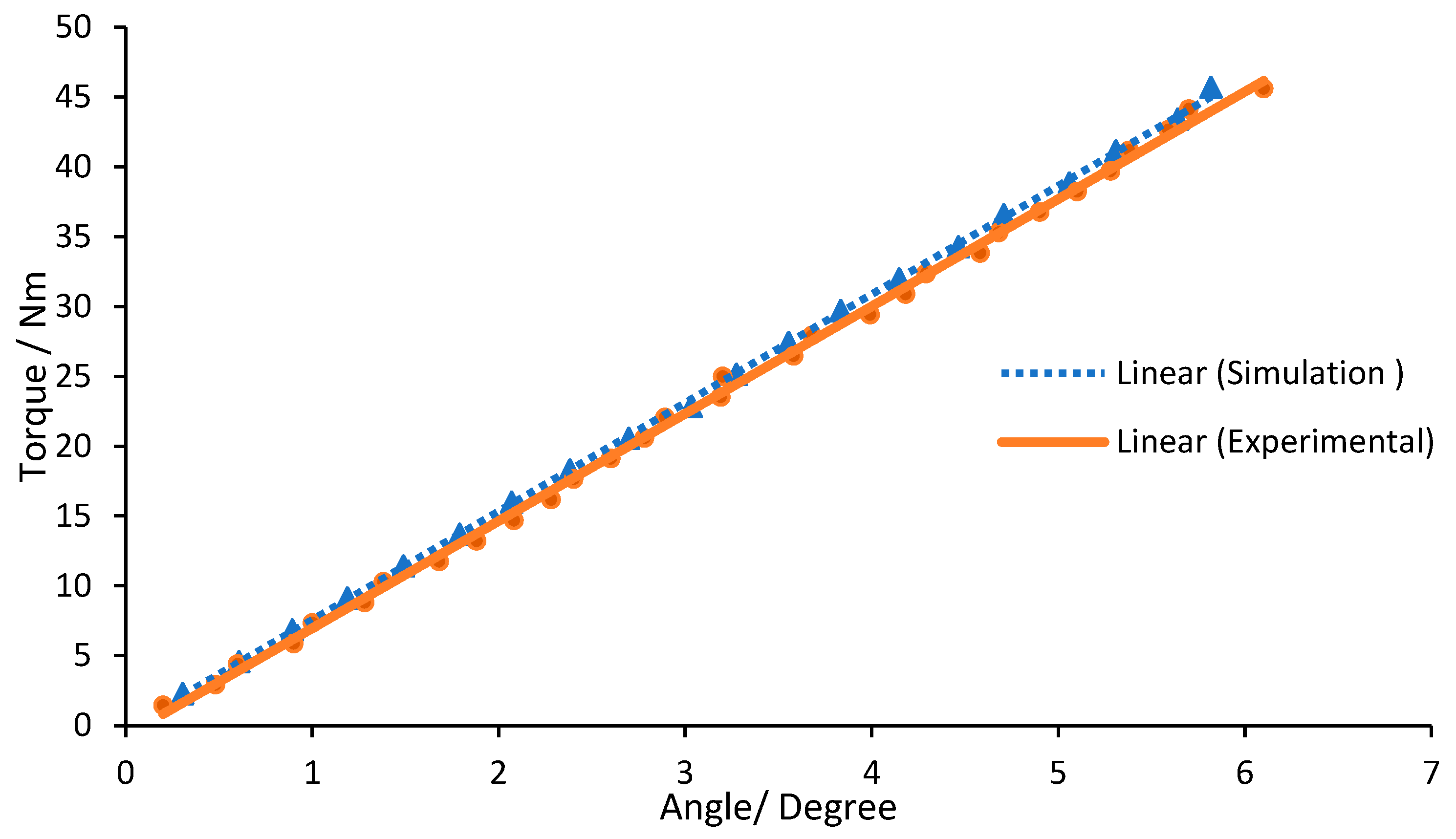
5.1. Stiffness Characteristics
5.2. Overall Spring Characteristics
6. Conclusions and Recommendations
Author Contributions
Funding
Institutional Review Board Statement
Informed Consent Statement
Data Availability Statement
Acknowledgments
Conflicts of Interest
References
- Brinckmann, P.; Frobin, W.; Biggemann, M.; Hilweg, D.; Seidel, S.; Burton, K.; Tillotson, M.; Sandover, J.; Atha, J.; Quinnell, R. Quantification of overload injuries to thoracolumbar vertebrae and discs in persons exposed to heavy physical exertions or vibration at the work-place. Clin. Biomech. 1994, 9, S3–S83. [Google Scholar] [CrossRef] [PubMed]
- Edlich, R.; Winters, K.L.; Hudson, M.A.; Britt, L.D.; Long, W.B., III. Prevention of Disabling Back Injuries in Nurses by the Use of Mechanical Patient Lift Systems. J. Long-Term Eff. Med. Implant. 2004, 14, 14. [Google Scholar] [CrossRef] [PubMed]
- Baltrusch, S.J.; Houdijk, H.; van Dieën, J.H.; van Bennekom, C.A.M.; de Kruif, A.J.T.C.M. Perspectives of End Users on the Potential Use of Trunk Exoskeletons for People With Low-Back Pain: A Focus Group Study. Hum. Factors 2020, 62, 365–376. [Google Scholar] [CrossRef] [PubMed]
- de Looze, M.P.; Bosch, T.; Krause, F.; Stadler, K.S.; O’Sullivan, L.W. Exoskeletons for industrial application and their potential effects on physical work load. Ergonomics 2016, 59, 671–681. [Google Scholar] [CrossRef] [Green Version]
- Robla-Gómez, S.; Becerra, V.M.; Llata, J.R.; González-Sarabia, E.; Torre-Ferrero, C.; Pérez-Oria, J. Working Together: A Review on Safe Human-Robot Collaboration in Industrial Environments. IEEE Access 2017, 5, 26754–26773. [Google Scholar] [CrossRef]
- Pratt, G.A.; Williamson, M.M. Series elastic actuators. In Proceedings of the 1995 IEEE/RSJ International Conference on Intelligent Robots and Systems, Pittsburgh, PA, USA, 5–9 August 1995; Volume 391, pp. 399–406, Human Robot Interaction and Cooperative Robots. [Google Scholar]
- Carpino, G.; Accoto, D.; Sergi, F.; Luigi Tagliamonte, N.; Guglielmelli, E. A Novel Compact Torsional Spring for Series Elastic Actuators for Assistive Wearable Robots. J. Mech. Des. 2012, 134, 121002–121010. [Google Scholar] [CrossRef]
- Pratt, J.; Krupp, B.; Morse, C. Series elastic actuators for high fidelity force control. Ind. Robot. Int. J. 2002, 29, 234–241. [Google Scholar] [CrossRef]
- Eitel, E. The Rise of Soft Robots and the Actuators that Drive Them. Mach. Des. Sep 2013, 12, 30–36. [Google Scholar]
- Stienenw, A.H.; Hekman, E.E.; ter Braak, H.; Aalsma, A.M.; van der Helm, F.C.; van der Kooij, H. Design of a rotational hydroelastic actuator for a powered exoskeleton for upper limb rehabilitation. IEEE Trans. Biomed. Eng. 2010, 57, 728–735. [Google Scholar] [CrossRef]
- Zhang, T.; Huang, H. A Lower-Back Robotic Exoskeleton: Industrial Handling Augmentation Used to Provide Spinal Support. IEEE Robot. Autom. Mag. 2018, 25, 95–106. [Google Scholar] [CrossRef]
- Hyun, D.J.; Lim, H.; Park, S.; Nam, S. Singular Wire-Driven Series Elastic Actuation with Force Control for a Waist Assistive Exoskeleton, H-WEXv2. IEEE/ASME Trans. Mechatron. 2020, 25, 1026–1035. [Google Scholar] [CrossRef]
- Al-Dahiree, O.S.; Ghazilla, R.A.R.; Tokhi, M.O.; Yap, H.J.; Albaadani, E.A. Design of a Compact Energy Storage with Rotary Series Elastic Actuator for Lumbar Support Exoskeleton. Machines 2022, 10, 584. [Google Scholar] [CrossRef]
- Al-Dahiree, O.S.; Ghazilla, R.A.R.; Yap, H.J.; Tokhi, M.O.; Yoong, G.W. Modeling and Dynamic performance of Energy Storage -Rotary Series Elastic Actuator for Lumbar Support Exoskeleton. In Proceedings of the 2022 IEEE 10th Conference on Systems, Process & Control (ICSPC), Malacca, Malaysia, 17 December 2022; pp. 208–216. [Google Scholar]
- Lagoda, C.; Schouten, A.C.; Stienen, A.H.A.; Hekman, E.E.G.; van der Kooij, H. Design of an electric Series Elastic Actuated Joint for robotic gait rehabilitation training. In Proceedings of the 2010 3rd Ieee Ras and Embs International Conference on Biomedical Robotics and Biomechatronics, Tokyo, Japan, 26–29 September 2010; pp. 21–26. [Google Scholar]
- Accoto, D.; Carpino, G.; Sergi, F.; Tagliamonte, N.L.; Zollo, L.; Guglielmelli, E. Design and Characterization of a Novel High-Power Series Elastic Actuator for a Lower Limb Robotic Orthosis. Int. J. Adv. Robot. Syst. 2013, 10, 12. [Google Scholar] [CrossRef]
- Irmscher, C.; Woschke, E.; May, E.; Daniel, C. Design, optimisation and testing of a compact, inexpensive elastic element for series elastic actuators. Med. Eng. Phys. 2018, 52, 84–89. [Google Scholar] [CrossRef] [PubMed]
- dos Santos, W.M.; Caurin, G.A.P.; Siqueira, A.A.G. Design and control of an active knee orthosis driven by a rotary Series Elastic Actuator. Control. Eng. Pract. 2017, 58, 307–318. [Google Scholar] [CrossRef]
- Paine, N.; Mehling, J.S.; Holley, J.; Radford, N.; Johnson, G.; Fok, C.; Sentis, L. Actuator Control for the NASA-JSC Valkyrie Humanoid Robot: A Decoupled Dynamics Approach for Torque Control of Series Elastic Robots. J. Field Robot. 2015, 32, 378–396. [Google Scholar] [CrossRef]
- Cummings, J.P.; Ruiken, D.; Wilkinson, E.L.; Lanighan, M.W.; Grupen, R.A.; Sup, F.C. A Compact, Modular Series Elastic Actuator. J. Mech. Robot. 2016, 8, 11. [Google Scholar] [CrossRef]
- Zhang, S.; Zhu, Q.; Wu, J.; Xiong, R.; Gu, Y. Design and Compliance Control of Rehabilitation Exoskeleton for Elbow Joint Anchylosis. In Proceedings of the 2020 IEEE/ASME International Conference on Advanced Intelligent Mechatronics (AIM), Boston, MA, USA, 6–9 July 2020; pp. 1896–1901. [Google Scholar]
- Wang, L.; Du, Z.; Dong, W.; Shen, Y.; Zhao, G. Intrinsic Sensing and Evolving Internal Model Control of Compact Elastic Module for a Lower Extremity Exoskeleton. Sensors 2018, 18, 909. [Google Scholar] [CrossRef] [Green Version]
- Long, Y.; Du, Z.-j.; Chen, C.-f.; Wang, W.-d.; Dong, W. Development of a lower extremity wearable exoskeleton with double compact elastic module: Preliminary experiments. Mech. Sci. 2017, 8, 249–258. [Google Scholar] [CrossRef] [Green Version]
- Yildirim, M.C.; Sendur, P.; Kansizoglu, A.T.; Uras, U.; Bilgin, O.; Emre, S.; Yapici, G.G.; Arik, M.; Ugurlu, B. Design and development of a durable series elastic actuator with an optimized spring topology. Proc. Inst. Mech. Eng. Part C J. Mech. Eng. Sci. 2021, 235, 7848–7858. [Google Scholar] [CrossRef]
- Zhang, T.; Tran, M.; Huang, H. Admittance Shaping-Based Assistive Control of SEA-Driven Robotic Hip Exoskeleton. IEEE/ASME Trans. Mechatron. 2019, 24, 1508–1519. [Google Scholar] [CrossRef]
- Zhang, T.; Xia, J. Development of a Clutchable Series Elastic Actuator for Robotic Hip Exoskeleton. In Proceedings of the 2019 IEEE International Conference on Cybernetics and Intelligent Systems (CIS) and IEEE Conference on Robotics, Automation and Mechatronics (RAM), Bangkok, Thailand, 18–20 November 2019; pp. 269–274. [Google Scholar]
- Knox, B.T.; Schmiedeler, J.P. A Unidirectional Series-Elastic Actuator Design Using a Spiral Torsion Spring. J. Mech. Des. 2009, 131, 125001–125005. [Google Scholar] [CrossRef]
- Daniyan, I.A. Application of Design for Manufacturing and Assembly: Development of a Multifeedstock Biodiesel Processor; IntechOpen: London, UK, 2018. [Google Scholar]
- Lucchetta, G.; Bariani, P.; Knight, W. Integrated design analysis for product simplification. CIRP Ann. 2005, 54, 147–150. [Google Scholar] [CrossRef]
- Anderson, D.M. Design for Manufacturability, 1st ed.; Productivity Press: New York, NY, USA, 2014. [Google Scholar]
- Dowlatshahi, S. An integrated manufacturing system design: An applied approach. Int. J. Prod. Econ. 1995, 42, 187–199. [Google Scholar] [CrossRef]
- Chao, N.-H. An Intelligent Cad System for Mechanical Design. In Artificial Intelligence in Engineering Design; Tong, C., Sriram, D., Eds.; Academic Press: San Diego, CA, USA, 1992; pp. 199–222. [Google Scholar]
- Păcurar, A.; Păcurar, R.; Erőss, B.; Popister, F.; Otel, C.C. Decreasing of the manufacturing time for a thermoforming mold by applying the DFM principles. MATEC Web Conf. 2017, 137, 01008. [Google Scholar] [CrossRef] [Green Version]
- Paluska, D.; Herr, H. The effect of series elasticity on actuator power and work output: Implications for robotic and prosthetic joint design. Robot. Auton. Syst. 2006, 54, 667–673. [Google Scholar] [CrossRef]
- Hurst, J.; Rizzi, A.; Hobbelen, D. Series elastic actuation: Potential and pitfalls. In Proceedings of the International Conference on Climbing and Walking Robots, Madrid, Spain, 22–24 September 2004. [Google Scholar]
- Zolfagharian, A.; Lakhi, M.; Ranjbar, S.; Tadesse, Y.; Bodaghi, M. 3D printing non-assembly compliant joints for soft robotics. Results Eng. 2022, 15, 100558. [Google Scholar] [CrossRef]
- Robinson, D.W. Design and Analysis of Series Elasticity in Closed-loop Actuator Force Control. Ph.D. Thesis, Massachusetts Institute of Technology, Cambridge, MA, USA, 2000. [Google Scholar]
- Tagliamonte, N.L.; Sergi, F.; Carpino, G.; Accoto, D.; Guglielmelli, E. Design of a Variable Impedance Differential Actuator for Wearable Robotics Applications. In Proceedings of the Ieee/Rsj 2010 International Conference on Intelligent Robots and Systems, Taipei, Taiwan, 18–22 October 2010; pp. 2639–2644. [Google Scholar]
- Yang, J. Control method and experimental research on elastic actuation of exoskeleton robot. Master’s Thesis, Harbin Institute of Technology, Harbin, China, 2014. [Google Scholar]
- Woo, H.; Na, B.; Kong, K. Design of a compact rotary series elastic actuator for improved actuation transparency and mechanical safety. In Proceedings of the 2017 IEEE International Conference on Robotics and Automation (ICRA), Singapore, 29 May–3 June 2017; pp. 1872–1877. [Google Scholar]
- Giovacchini, F.; Vannetti, F.; Fantozzi, M.; Cempini, M.; Cortese, M.; Parri, A.; Yan, T.; Lefeber, D.; Vitiello, N. A lightweight active orthosis for hip movement assistance. Robot. Auton. Syst. 2015, 73, 123–134. [Google Scholar] [CrossRef]
- Yu, H.; Huang, S.; Chen, G.; Pan, Y.; Guo, Z. Human–Robot Interaction Control of Rehabilitation Robots With Series Elastic Actuators. IEEE Trans. Robot. 2015, 31, 1089–1100. [Google Scholar] [CrossRef]
- Kim, S.; Bae, J. Force-Mode Control of Rotary Series Elastic Actuators in a Lower Extremity Exoskeleton Using Model-Inverse Time Delay Control. IEEE/ASME Trans. Mechatron. 2017, 22, 1392–1400. [Google Scholar] [CrossRef]
- Kong, K.; Bae, J.; Tomizuka, M. Control of Rotary Series Elastic Actuator for Ideal Force-Mode Actuation in Human–Robot Interaction Applications. IEEE/ASME Trans. Mechatron. 2009, 14, 105–118. [Google Scholar] [CrossRef]
- Wang, S.; Meijneke, C.; Kooij, H.v.d. Modeling, design, and optimization of Mindwalker series elastic joint. In Proceedings of the 2013 IEEE 13th International Conference on Rehabilitation Robotics (ICORR), Seattle, WA, USA, 24–26 June 2013; pp. 1–8. [Google Scholar]
- Zhang, T.; Huang, H. Design and Control of a Series Elastic Actuator With Clutch for Hip Exoskeleton for Precise Assistive Magnitude and Timing Control and Improved Mechanical Safety. IEEE/ASME Trans. Mechatron. 2019, 24, 2215–2226. [Google Scholar] [CrossRef]
- Mühl, F.; Damon, J.; Dietrich, S.; Schulze, V. Simulation of induction hardening: Simulative sensitivity analysis with respect to material parameters and the surface layer state. Comput. Mater. Sci. 2020, 184, 109916. [Google Scholar] [CrossRef]
- Rychlewski, J. On Hooke’s Law. J. Appl. Math. Mech. 1984, 48, 303–314. [Google Scholar] [CrossRef]
- CAMM Metals, Inc. 4 Features That Make Waterjet Cutting the Right Choice for Your Next Metal Fabrication Project. Available online: https://inbound.cammmetals.com/blog/4-features-that-make-waterjet-cutting-the-right-choice-for-your-next-metal-fabrication-project (accessed on 29 October 2018).


| Design Parameter | Desired Value for the Proposed Design |
|---|---|
| Output torque of the RSEA | 45.7 Nm |
| Maximum thickness | 10 mm |
| Maximum outer diameter | 85 mm |
| Minimum inner diameter | 20 mm |
| Torsional spring stiffness | 200–800 Nm/rad |
| Maximum weight | 150 g |
| Spring material | Low-alloy steel AISI 4140 |
| yield strength | 1400 MPA |
| Angular deflection | 5.8 Degree |
| Weight-to-torque ratio | 3 g/Nm |
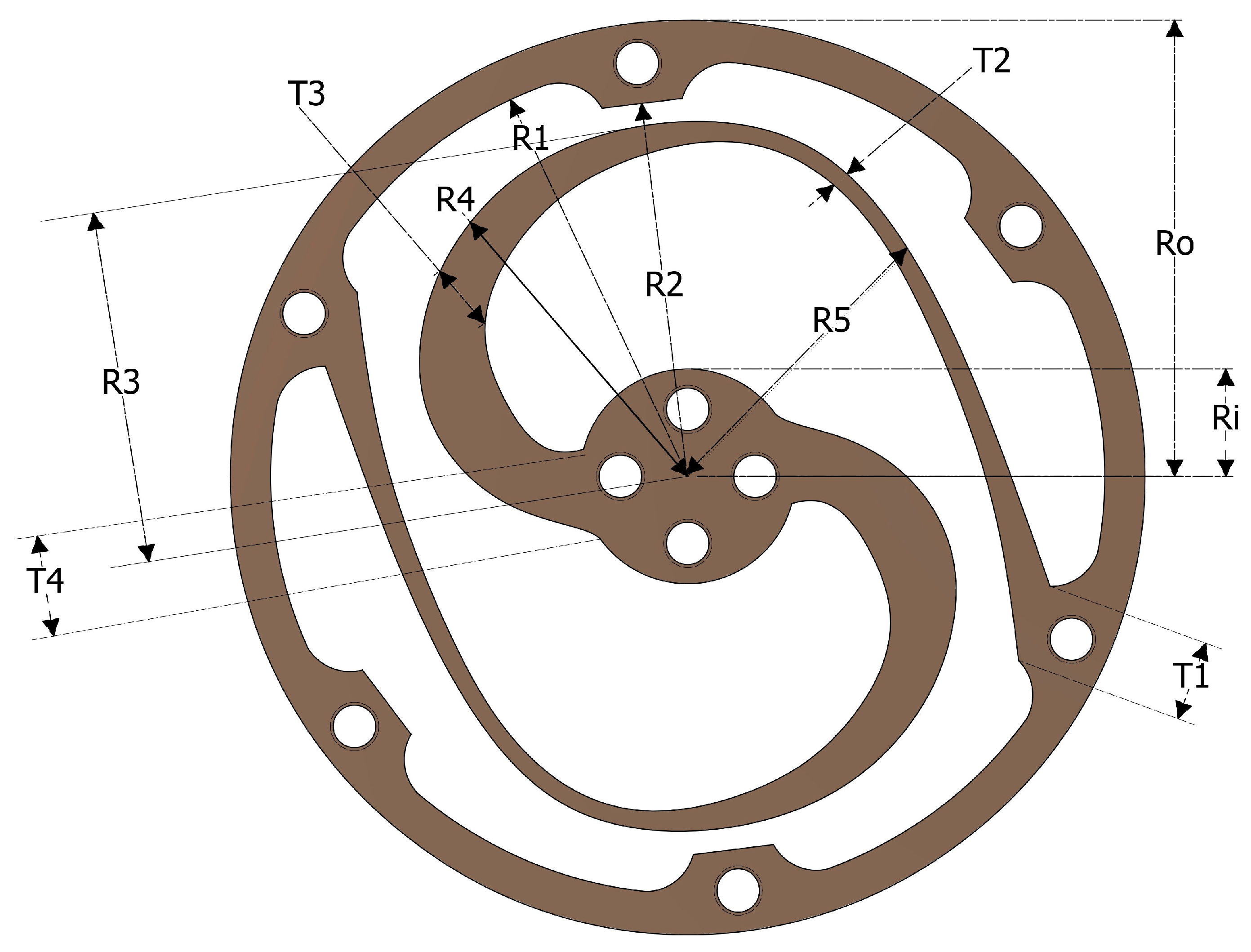
| Parameter | Minimum | Maximum | Minimum Increment |
|---|---|---|---|
| R3 | 25 | 33 | 0.2 |
| R4 | 22 | 32 | 0.2 |
| R5 | 23 | 33 | 0.5 |
| T2 | 1 | 4 | 0.1 |
| T3 | 3 | 7 | 0.1 |
| T4 | 4.5 | 16 | 0.5 |
| t | 4 | 16 | 2 |
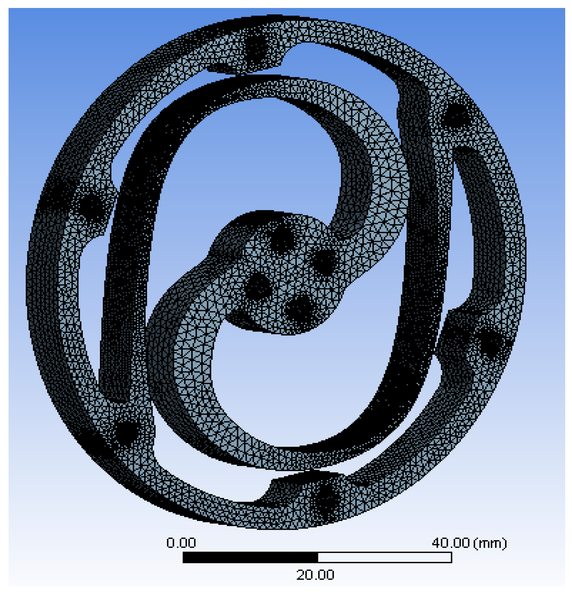
| Mesh Property/Spring Type | Number of Nodes Produced |
|---|---|
| Element Quantity Fluctuation | 100,000 to 500,000 |
| Convergence | 250,000–300,000 |
| Actual optimization | 292,842 |
| Parameter | Optimized |
|---|---|
| R3 | 32.8 |
| R4 | 31.2 |
| R5 | 28.5 |
| T2 | 1.6 |
| T3 | 5.2 |
| T4 | 8.5 |
| T | 8 |
Disclaimer/Publisher’s Note: The statements, opinions and data contained in all publications are solely those of the individual author(s) and contributor(s) and not of MDPI and/or the editor(s). MDPI and/or the editor(s) disclaim responsibility for any injury to people or property resulting from any ideas, methods, instructions or products referred to in the content. |
© 2023 by the authors. Licensee MDPI, Basel, Switzerland. This article is an open access article distributed under the terms and conditions of the Creative Commons Attribution (CC BY) license (https://creativecommons.org/licenses/by/4.0/).
Share and Cite
Al-Dahiree, O.S.; Ghazilla, R.A.R.; Tokhi, M.O.; Yap, H.J.; Gul, M. Design and Characterization of a Low-Cost and Efficient Torsional Spring for ES-RSEA. Sensors 2023, 23, 3705. https://doi.org/10.3390/s23073705
Al-Dahiree OS, Ghazilla RAR, Tokhi MO, Yap HJ, Gul M. Design and Characterization of a Low-Cost and Efficient Torsional Spring for ES-RSEA. Sensors. 2023; 23(7):3705. https://doi.org/10.3390/s23073705
Chicago/Turabian StyleAl-Dahiree, Omar Sabah, Raja Ariffin Raja Ghazilla, Mohammad Osman Tokhi, Hwa Jen Yap, and Mustabshirha Gul. 2023. "Design and Characterization of a Low-Cost and Efficient Torsional Spring for ES-RSEA" Sensors 23, no. 7: 3705. https://doi.org/10.3390/s23073705