
A Novel Real-Time Autonomous Crack Inspection System Based on Unmanned Aerial Vehicles


Abstract
:1. Introduction
- A deep learning-based crack detection method is proposed. We have built a dataset that contains 4000 crack images with three types of concrete textures. The detector shows promising performance in crack detection on unseen cracks. No prior knowledge of the cracks in the structure is needed.
- The improved YOLOv4-SE and YOLOv4-tiny-SE incorporating attention mechanism in neural networks are designed. We have proved that our improved models outperformed the YOLOv4-original models with higher mAP performance on multiple tests.
- The fully onboard crack localization system is developed. Our system solely utilizes an RGBD camera and precisely locates the crack positions with cm-level accuracy. Moreover, the autonomous UAV system with two inspection trajectories, straight-line and zig-zag, is designed to perform crack inspection tasks for the structure.
- We present extensive test results in different experimental setups to validate our system. Our code, dataset, and the pre-trained weights are released as an open-source package to the research community.
2. Materials and Methods
2.1. System Overview
2.1.1. The UAV Hardware Components
2.1.2. The Inspection System Software Architecture
2.2. Training Dataset Preparation
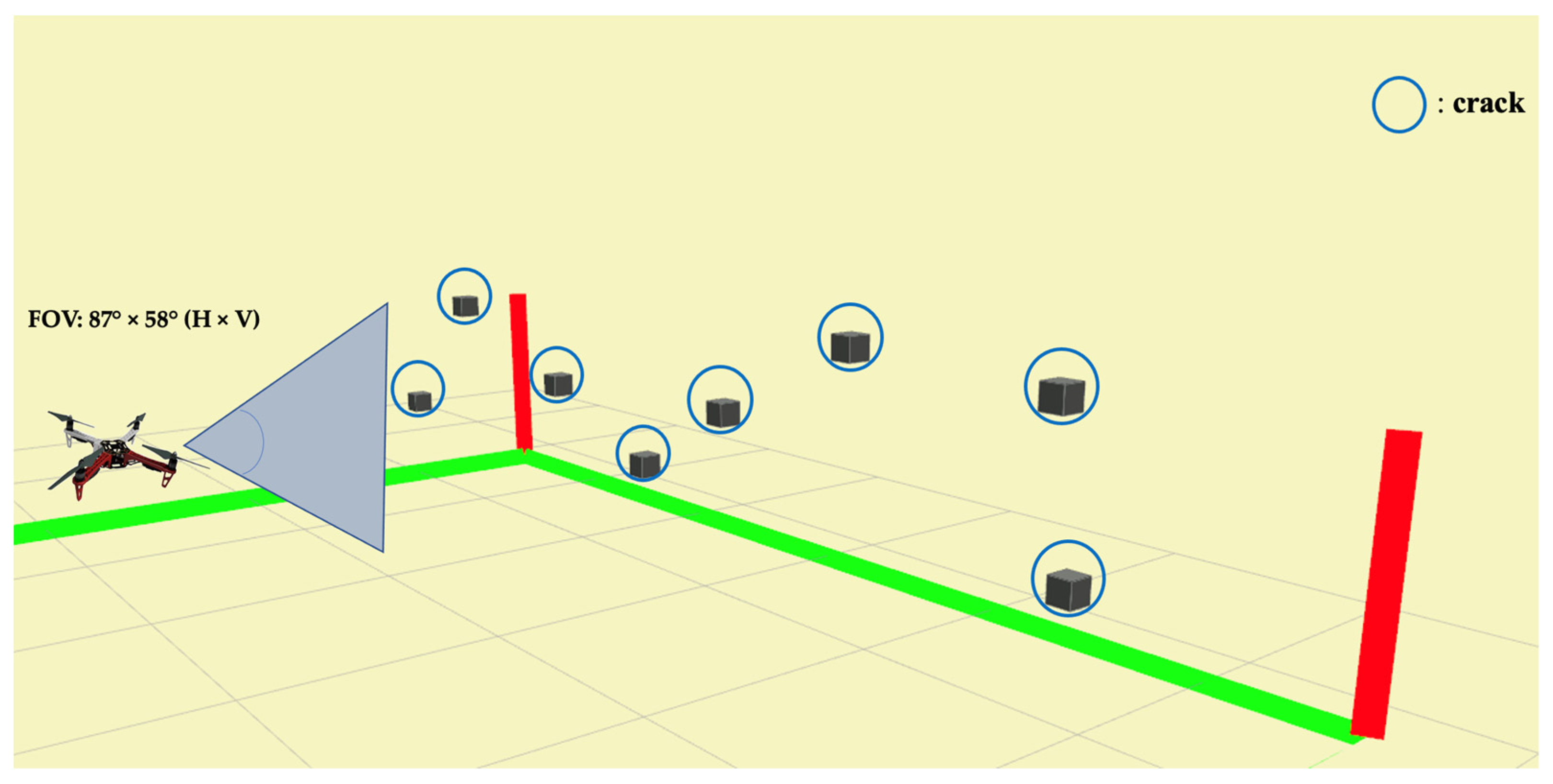
2.3. Inspection Path Planning
2.3.1. Path Planning
2.3.2. Simulation-to-Real
2.4. Crack Detection and Localization
2.4.1. Camera Model
2.4.2. Coordinate Transformation
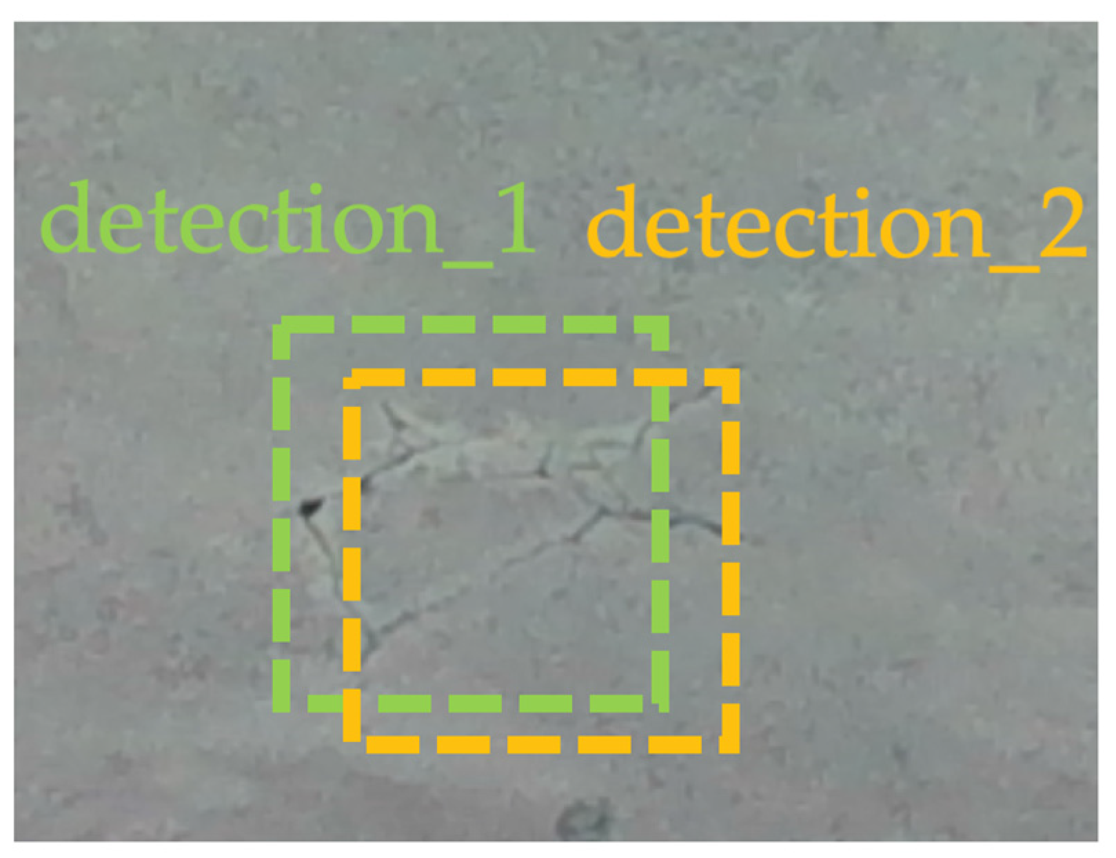
2.4.3. Rejecting Duplicated Crack Detections
| Algorithm 1: Rejecting duplicate detection records | |
| 1: | Distance threshold ← 150 mm |
| 2: | while detection function start do |
| 3: | if crack detection flag is TRUE then |
| 4: | for each detected crack do |
| 5: | calculate the 3D world coordinate of current crack |
| 6: | distance difference ← calculate the distance between current crack and each previous identified crack |
| 7: | if distance difference < distance threshold then |
| 8: | mark it as duplicates detection record |
| 9: | reject duplicate detections |
| 10: | end if |
| 11: | end for |
| 12: | end if |
| 13: | end while |
2.4.4. Improved YOLOv4 Models with Attention Mechanism
3. Experimental Results
- The crack detection performance of the improved YOLOv4 with attention mechanism on various crack datasets (Section 3.1);
- The real-time multi-cracks detection performance in the flight tests, and the generalization capability on unseen cracks in real flight experiments (Section 3.2);
- The cracks localization performance in real flight experiments with assessments on Root-Mean-Square Errors (RMSE), and crack localization errors in 3D space (Section 3.3).
3.1. Crack Detection Performance of the Improved YOLOv4 with Attention Mechanism
3.2. Multi-Cracks Detection Performance and Generalization Capability
3.3. Cracks Localization Performance
4. Discussion and Future Work
5. Conclusions
Supplementary Materials
Author Contributions
Funding
Institutional Review Board Statement
Informed Consent Statement
Data Availability Statement
Acknowledgments
Conflicts of Interest
References
- Chakraborty, J.; Katunin, A.; Klikowicz, P.; Salamak, M. Early Crack Detection of Reinforced Concrete Structure Using Embedded Sensors. Sensors 2019, 19, 3879. [Google Scholar] [CrossRef] [Green Version]
- Zhao, J.; Bao, T.; Chen, R. Crack monitoring capability of plastic optical fibers for concrete structures. Opt. Fiber Technol. 2015, 24, 70–76. [Google Scholar] [CrossRef]
- Dinh, T.H.; Ha, Q.P.; La, H.M. Computer vision-based method for concrete crack detection. In Proceedings of the 14th International Conference on Control, Automation, Robotics and Vision (ICARCV), Phuket, Thailand, 13–15 November 2016; pp. 1–6. [Google Scholar]
- Koch, C.; Doycheva, K.; Kasireddy, V.; Akinci, B.; Fieguth, P. A review on computer vision based defect detection and condition assessment of concrete and asphalt civil infrastructure (vol 29, pg 196, 2015). Adv. Eng. Inform. 2016, 30, 208–210. [Google Scholar] [CrossRef]
- Feng, C.C.; Zhang, H.; Wang, S.; Li, Y.L.; Wang, H.R.; Yan, F. Structural Damage Detection using Deep Convolutional Neural Network and Transfer Learning. Ksce J. Civ. Eng. 2019, 23, 4493–4502. [Google Scholar] [CrossRef]
- Li, Y.D.; Li, H.G.; Wang, H.R. Pixel-Wise Crack Detection Using Deep Local Pattern Predictor for Robot Application. Sensors 2018, 18, 3042. [Google Scholar] [CrossRef] [Green Version]
- Krizhevsky, A.; Sutskever, I.; Hinton, G.E. ImageNet Classification with Deep Convolutional Neural Networks. Commun. Acm 2017, 60, 84–90. [Google Scholar] [CrossRef] [Green Version]
- Kivinen, J.J.; Williams, C.K.I.; Heess, N. Visual Boundary Prediction: A Deep Neural Prediction Network and Quality Dissection. Artif. Intell. Stat. 2014, 33, 512–521. [Google Scholar]
- Zhang, L.; Yang, F.; Zhang, Y.D.; Zhu, Y.J. Road Crack Detection Using Deep Convolutional Neural Network. In Proceedings of the 2016 IEEE International Conference on Image Processing (ICIP), Phoenix, AZ, USA, 25–28 September 2016; pp. 3708–3712. [Google Scholar]
- Fang, F.; Li, L.Y.; Rice, M.; Lim, J.H. Towards Real-Time Crack Detection Using a Deep Neural Network with a Bayesian Fusion Algorithm. IEEE Image Proc. 2019, 2976–2980. [Google Scholar]
- Alsamhi, S.H.; Shvetsov, A.V.; Kumar, S.; Hassan, J.; Alhartomi, M.A.; Shvetsova, S.V.; Sahal, R.; Hawbani, A. Computing in the Sky: A Survey on Intelligent Ubiquitous Computing for UAV-Assisted 6G Networks and Industry 4.0/5.0. Drones 2022, 6, 177. [Google Scholar] [CrossRef]
- Nooralishahi, P.; Ibarra-Castanedo, C.; Deane, S.; Lopez, F.; Pant, S.; Genest, M.; Avdelidis, N.P.; Maldague, X.P.V. Drone-Based Non-Destructive Inspection of Industrial Sites: A Review and Case Studies. Drones 2021, 5, 106. [Google Scholar] [CrossRef]
- Grosso, R.; Mecca, U.; Moglia, G.; Prizzon, F.; Rebaudengo, M. Collecting Built Environment Information Using UAVs: Time and Applicability in Building Inspection Activities. Sustainability 2020, 12, 4731. [Google Scholar] [CrossRef]
- Kim, H.; Lee, J.; Ahn, E.; Cho, S.; Shin, M.; Sim, S.H. Concrete Crack Identification Using a UAV Incorporating Hybrid Image Processing. Sensors 2017, 17, 2052. [Google Scholar] [CrossRef] [Green Version]
- Li, J.; Li, X.; Liu, K.; Yao, Z. Crack Identification for Bridge Structures Using an Unmanned Aerial Vehicle (UAV) Incorporating Image Geometric Correction. Buildings 2022, 12, 1869. [Google Scholar] [CrossRef]
- Yu, H.; Yang, W.; Zhang, H.; He, W. A UAV-based crack inspection system for concrete bridge monitoring. In Proceedings of the 2017 IEEE International Geoscience and Remote Sensing Symposium (IGARSS), Fort Worth, TX, USA, 23–28 July 2017; pp. 3305–3308. [Google Scholar]
- Woo, H.J.; Seo, D.M.; Kim, M.S.; Park, M.S.; Hong, W.H.; Baek, S.C. Localization of Cracks in Concrete Structures Using an Unmanned Aerial Vehicle. Sensors 2022, 22, 6711. [Google Scholar] [CrossRef] [PubMed]
- Saleem, M.R.; Park, J.W.; Lee, J.H.; Jung, H.J.; Sarwar, M.Z. Instant bridge visual inspection using an unmanned aerial vehicle by image capturing and geo-tagging system and deep convolutional neural network. Struct. Health Monit. Int. J. 2021, 20, 1760–1777. [Google Scholar] [CrossRef]
- Kim, I.-H.; Yoon, S.; Lee, J.H.; Jung, S.; Cho, S.; Jung, H.-J. A Comparative Study of Bridge Inspection and Condition Assessment between Manpower and a UAS. Drones 2022, 6, 355. [Google Scholar] [CrossRef]
- Redmon, J.; Divvala, S.; Girshick, R.; Farhadi, A. You only look once: Unified, real-time object detection. In Proceedings of the IEEE Conference on Computer Vision and Pattern Recognition, Las Vegas, NV, USA, 26 June–1 July 2016; pp. 779–788. [Google Scholar]
- Redmon, J.; Farhadi, A. YOLO9000: Better, Faster, Stronger. In Proceedings of the 30th IEEE Conference on Computer Vision and Pattern Recognition (Cvpr 2017), Honolulu, HI, USA, 21–26 July 2017; pp. 6517–6525. [Google Scholar]
- Redmon, J.; Ali, A.F. YOLOv3: An Incremental Improvement. arXiv 2018, arXiv:1804.02767. [Google Scholar]
- Bochkovskiy, A.; Wang, C.-Y.; Liao, H.-Y.M. Yolov4: Optimal speed and accuracy of object detection. arXiv 2020, arXiv:2004.10934. [Google Scholar]
- Jocher, G.; Stoken, A.; Borovec, J.; Changyu, L.; Hogan, A. ultralytics/yolov5: V3. 1-bug fixes and performance improvements. Zenodo, 2020. [Google Scholar] [CrossRef]
- Yun, S.; Han, D.; Oh, S.J.; Chun, S.; Choe, J.; Yoo, Y. CutMix: Regularization Strategy to Train Strong Classifiers with Localizable Features. In Proceedings of the 2019 IEEE/Cvf International Conference on Computer Vision (Iccv 2019), Seoul, Korea, 27 October–2 November 2019; pp. 6022–6031. [Google Scholar]
- Rezatofighi, H.; Tsoi, N.; Gwak, J.; Sadeghian, A.; Reid, I.; Savarese, S. Generalized Intersection over Union: A Metric and A Loss for Bounding Box Regression. In Proceedings of the 2019 IEEE/Cvf Conference on Computer Vision and Pattern Recognition (Cvpr 2019), Long Beach, CA, USA, 15–20 June 2019; pp. 658–666. [Google Scholar]
- Hu, J.; Shen, L.; Sun, G. Squeeze-and-Excitation Networks. In Proceedings of the 2018 IEEE/Cvf Conference on Computer Vision Pattern Recognition (Cvpr), Salt Lake, UT, USA, 18–22 June 2018; pp. 7132–7141. [Google Scholar]
- Wang, Q.W.B.; Zhu, P.; Li, P.; Zuo, W.; Hu, Q. ECA-Net: Efficient Channel Attention for Deep Convolutional Neural Networks. In Proceedings of the IEEE/CVF Conference on Computer Vision and Pattern Recognition (CVPR), Seattle, WA, USA, 13–20 June 2020; pp. 11534–11542. [Google Scholar]
- Woo, S.H.; Park, J.; Lee, J.Y.; Kweon, I.S. CBAM: Convolutional Block Attention Module. Comput. Vis. 2018, 11211, 3–19. [Google Scholar]
- Hou, Q.B.; Zhou, D.Q.; Feng, J.S. Coordinate Attention for Efficient Mobile Network Design. In Proceedings of the 2021 IEEE/Cvf Conference on Computer Vision and Pattern Recognition, Cvpr 2021, Nashville, TN, USA, 20–25 June 2021; pp. 13708–13717. [Google Scholar]
- Yu, L.; Zhu, J.; Zhao, Q.; Wang, Z. An Efficient YOLO Algorithm with an Attention Mechanism for Vision-Based Defect Inspection Deployed on FPGA. Micromachines 2022, 13, 1058. [Google Scholar] [CrossRef]
- Sun, J.; Ge, H.; Zhang, Z. AS-YOLO: An improved YOLOv4 based on attention mechanism and SqueezeNet for person detection. In Proceedings of the 2021 IEEE 5th Advanced Information Technology, Electronic and Automation Control Conference (IAEAC), Chongqing, China, 12–14 March 2021; pp. 1451–1456. [Google Scholar]
- Feng, Y.R.; Tse, K.; Chen, S.Y.; Wen, C.Y.; Li, B.Y. Learning-Based Autonomous UAV System for Electrical and Mechanical (E&M) Device Inspection. Sensors 2021, 21, 1385. [Google Scholar] [CrossRef]
- Zhu, J.; Zhong, J.; Ma, T.; Huang, X.; Zhang, W.; Zhou, Y. Pavement distress detection using convolutional neural networks with images captured via UAV. Autom. Constr. 2022, 133, 103991. [Google Scholar] [CrossRef]


| Item | Description |
|---|---|
| Operating System | Ubuntu 18.04 (LTS) |
| CPU | Intel Core i7-10700KF@3.80 GHz |
| Memory | 64 GB |
| GPU | NVIDIA GeForce RTX3090 |
| Dimension (mm) | Crack 1 | Crack 2 | Crack 3 | Crack 4 | Crack5 | Crack 6 | Crack 7 | Crack 8 | Crack 9 |
|---|---|---|---|---|---|---|---|---|---|
| Width | 190 | 430 | 310 | 420 | 190 | 230 | 190 | 170 | 140 |
| Height | 140 | 40 | 200 | 30 | 140 | 130 | 140 | 180 | 90 |
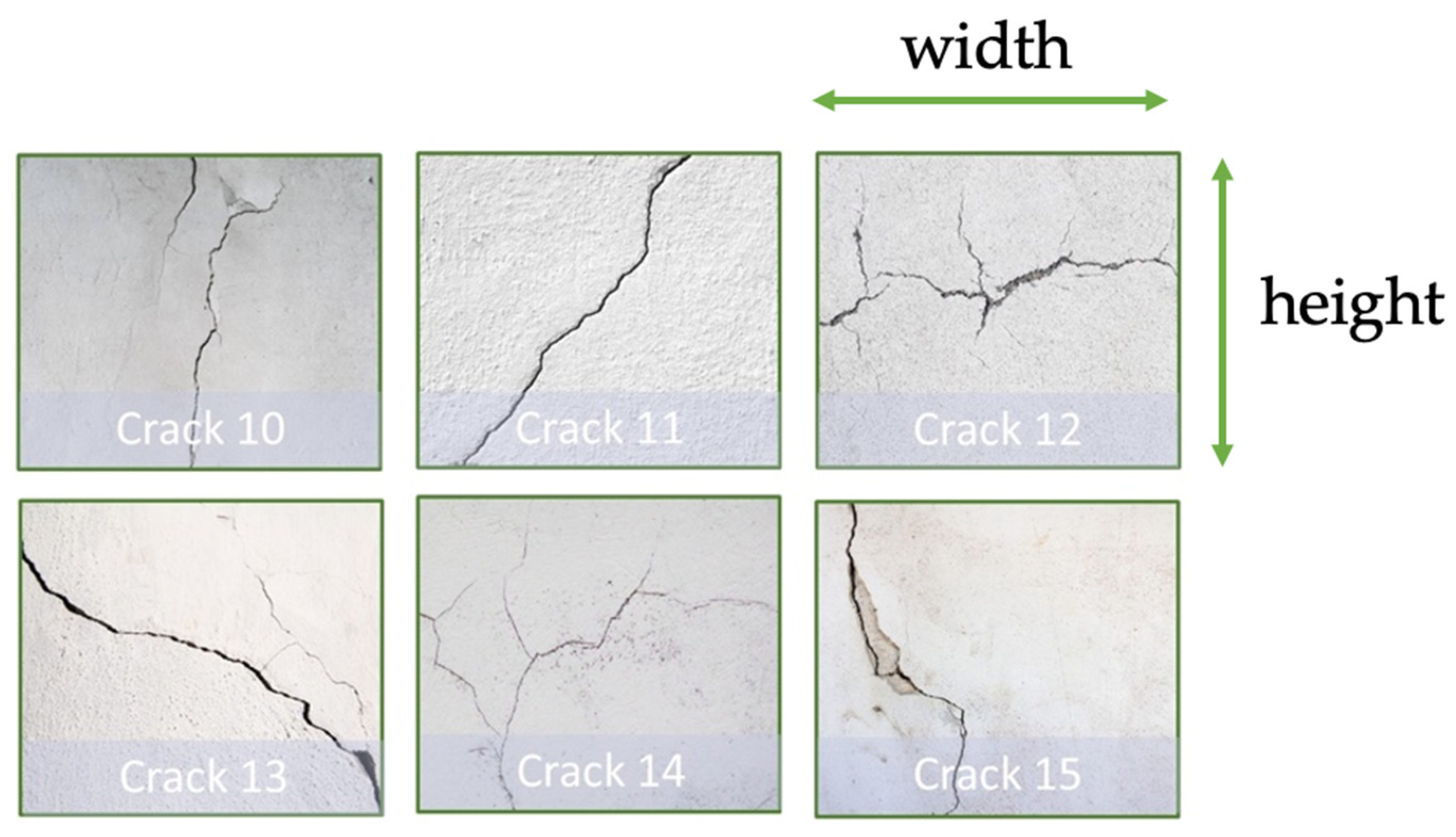
| Dimension (mm) | Crack 10 | Crack 11 | Crack 12 | Crack 13 | Crack 14 | Crack 15 |
|---|---|---|---|---|---|---|
| Width | 50 | 80 | 190 | 140 | 190 | 40 |
| Height | 150 | 110 | 140 | 110 | 105 | 85 |
| Models | Precision | Recall | |
|---|---|---|---|
| YOLOv4-original | 0.84 | 0.81 | 84.79% |
| YOLOv4-SE * (our method) | 0.85 | 0.88 | 90.02% |
| YOLOv4-tiny-original | 0.81 | 0.84 | 82.37% |
| YOLOv4-tiny-SE * (our method) | 0.83 | 0.96 | 85.46% |
| Models | Precision | Recall | |
|---|---|---|---|
| YOLOv4-original | 0.67 | 0.54 | 45.15% |
| YOLOv4-SE * (ours) | 0.76 | 0.48 | 48.69% |
| YOLOv4-tiny-original | 0.57 | 0.50 | 43.43% |
| YOLOv4-tiny-SE * (ours) | 0.62 | 0.55 | 45.02% |
| Measurement (mm) | Crack 1 | Crack 2 | Crack 3 | Crack 4 | Crack 5 | Crack 6 | Crack 7 | Crack 8 |
|---|---|---|---|---|---|---|---|---|
| Ground truth x | −2740 | −2100 | −1170 | −440 | 140 | 900 | 1860 | 1930 |
| Ground truth y | 3000 | 3000 | 3000 | 3000 | 3000 | 3000 | 3000 | 3000 |
| Ground truth z | 430 | 1030 | 730 | 460 | 780 | 1130 | 1080 | 470 |
| Straight-line trajectory inspection result | ||||||||
| Measured x | −2570 | −2079 | −1190 | −476 | 113 | 832 | 1818 | 1893 |
| Measured y | 2984 | 2931 | 2932 | 2980 | 2900 | 2903 | 2933 | 2935 |
| Measured z | 584 | 1054 | 720 | 522 | 895 | 1221 | 1182 | 590 |
| Error x | 170 | 21 | −20 | −36 | −27 | −68 | −42 | −37 |
| Error y | −16 | −69 | −68 | −20 | −100 | −97 | −67 | −65 |
| Error z | 154 | 24 | −10 | 62 | 115 | 91 | 102 | 120 |
| Zig-zag trajectory inspection result | ||||||||
| Measured x | −2868 | −2253 | −1181 | −468 | 122 | 853 | 1841 | 1871 |
| Measured y | 3190 | 3151 | 2960 | 2973 | 2931 | 2911 | 2907 | 2914 |
| Measured z | 570 | 1253 | 658 | 510 | 875 | 1187 | 1166 | 538 |
| Error x | −128 | −153 | −11 | −28 | −18 | −47 | −19 | −59 |
| Error y | 190 | 151 | −40 | −27 | −69 | −89 | −93 | −86 |
| Error z | 140 | 223 | −72 | 50 | 95 | 57 | 86 | 68 |
| Measurement (mm) | Crack 10 | Crack 11 | Crack 12 | Crack 13 | Crack 14 | Crack 15 |
|---|---|---|---|---|---|---|
| Ground truth x | −2150 | −1300 | 20 | 420 | 1750 | 1910 |
| Ground truth y | 3000 | 3000 | 3000 | 3000 | 3000 | 3000 |
| Ground truth z | 770 | 1120 | 840 | 1170 | 1120 | 900 |
| Straight-line trajectory inspection result | ||||||
| Measured x | −2243 | −1370 | −8 | 415 | 1681 | 1904 |
| Measured y | 2906 | 2926 | 2912 | 2935 | 2995 | 2966 |
| Measured z | 834 | 1203 | 890 | 1246 | 1223 | 1001 |
| Error x | −93 | −70 | −28 | −5 | −69 | −6 |
| Error y | −94 | −74 | −88 | −65 | −5 | −34 |
| Error z | 64 | 83 | 50 | 76 | 103 | 101 |
| Zig-zag trajectory inspection result | ||||||
| Measured x | −2266 | −1326 | −57 | 419 | 1858 | 1939 |
| Measured y | 2903 | 2938 | 2915 | 2940 | 3005 | 3009 |
| Measured z | 809 | 1180 | 960 | 1221 | 1052 | 1003 |
| Error x | −116 | −26 | −77 | −1 | 108 | 29 |
| Error y | −97 | −62 | −85 | −60 | 5 | 9 |
| Error z | 39 | 60 | 120 | 51 | −68 | 103 |
| Performance on Training Cracks | Performance on Unseen Cracks | ||
|---|---|---|---|
| Straight-Line Trajectory Results | |||
| Coordinate | RMSE Error (Unit: mm) | Coordinate | RMSE Error (Unit: mm) |
| x | 70 | x | 57 |
| y | 69 | y | 68 |
| z | 96 | z | 82 |
| Zig-zag trajectory results | |||
| x | 77 | x | 74 |
| y | 106 | y | 63 |
| z | 112 | z | 79 |
| Distance Error (mm) | Crack 1 | Crack 2 | Crack 3 | Crack 4 | Crack 5 | Crack 6 | Crack 7 | Crack 8 |
|---|---|---|---|---|---|---|---|---|
| Straight-line inspection | 230 | 76 | 72 | 75 | 155 | 149 | 129 | 141 |
| Zig-zag inspection | 268 | 310 | 83 | 63 | 119 | 116 | 128 | 124 |
| Distance error (mm) | Crack 10 | Crack 11 | Crack 12 | Crack 13 | Crack 14 | Crack 15 | Average | |
| Straight-line inspection | 147 | 132 | 105 | 100 | 125 | 106 | 130 | |
| Zig-zag inspection | 156 | 91 | 166 | 78 | 128 | 108 | ||
Disclaimer/Publisher’s Note: The statements, opinions and data contained in all publications are solely those of the individual author(s) and contributor(s) and not of MDPI and/or the editor(s). MDPI and/or the editor(s) disclaim responsibility for any injury to people or property resulting from any ideas, methods, instructions or products referred to in the content. |
© 2023 by the authors. Licensee MDPI, Basel, Switzerland. This article is an open access article distributed under the terms and conditions of the Creative Commons Attribution (CC BY) license (https://creativecommons.org/licenses/by/4.0/).
Share and Cite
Tse, K.-W.; Pi, R.; Sun, Y.; Wen, C.-Y.; Feng, Y. A Novel Real-Time Autonomous Crack Inspection System Based on Unmanned Aerial Vehicles. Sensors 2023, 23, 3418. https://doi.org/10.3390/s23073418
Tse K-W, Pi R, Sun Y, Wen C-Y, Feng Y. A Novel Real-Time Autonomous Crack Inspection System Based on Unmanned Aerial Vehicles. Sensors. 2023; 23(7):3418. https://doi.org/10.3390/s23073418
Chicago/Turabian StyleTse, Kwai-Wa, Rendong Pi, Yuxiang Sun, Chih-Yung Wen, and Yurong Feng. 2023. "A Novel Real-Time Autonomous Crack Inspection System Based on Unmanned Aerial Vehicles" Sensors 23, no. 7: 3418. https://doi.org/10.3390/s23073418