
IoT Smart Flooring Supporting Active and Healthy Lifestyles
 , , , , and
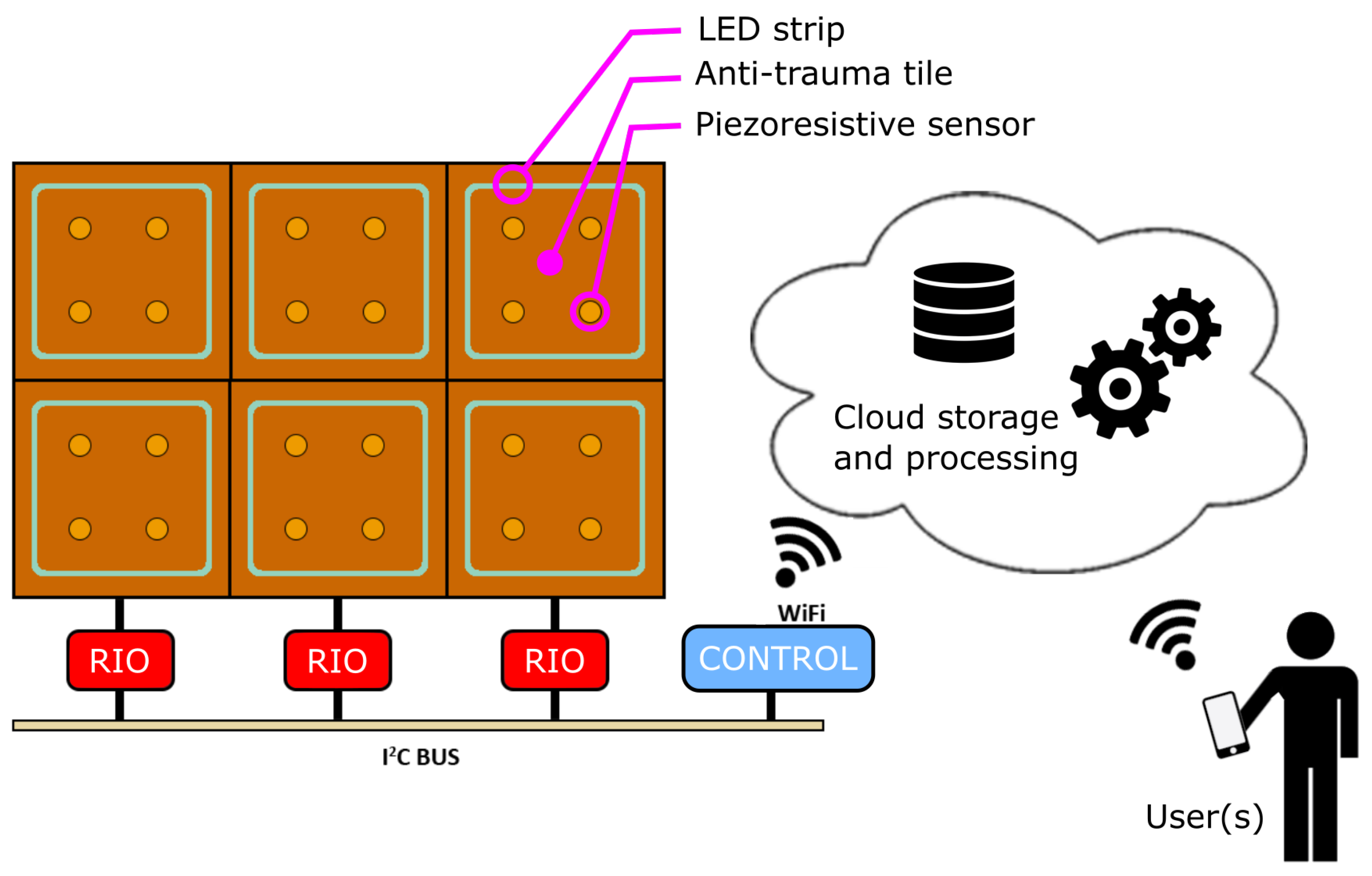
Abstract
:1. Introduction
2. Materials and Methods
2.1. Related Works
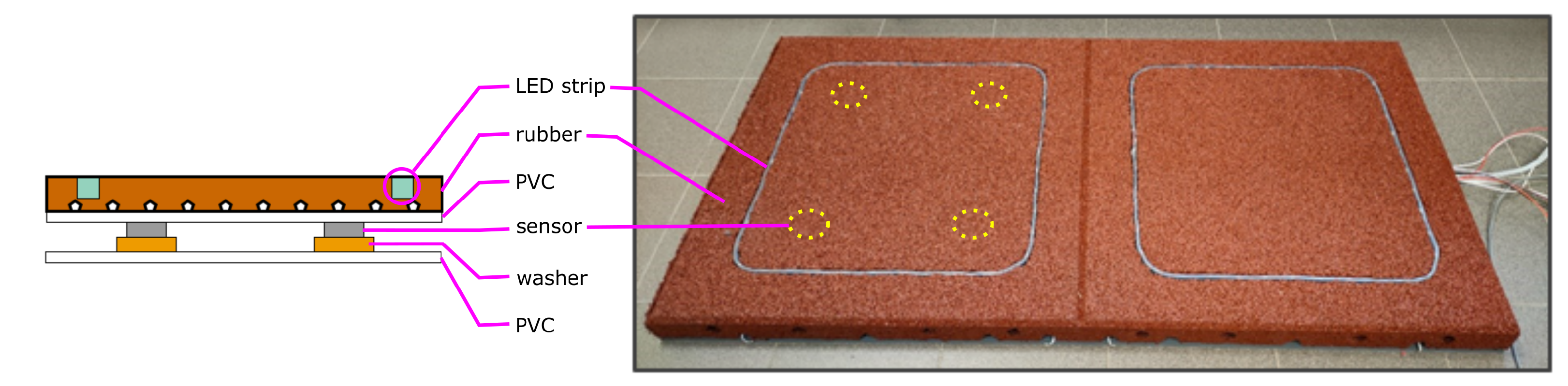
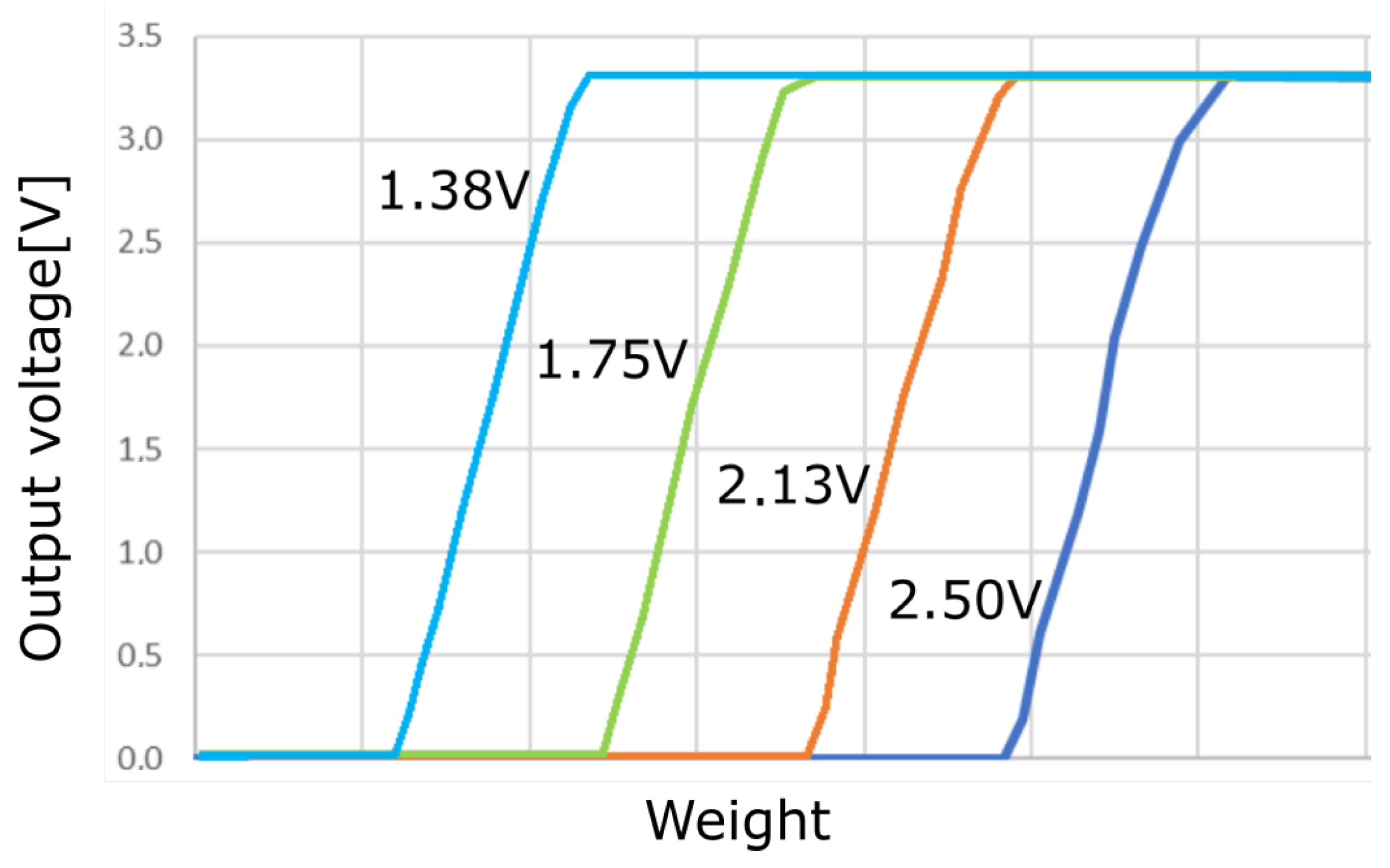
- The adoption of the standard anti-trauma layer as the floor surface is needed to ensure safety while practising PA. Anti-trauma rubber (usually obtained by recycling exhausted car tires) is quite a rough material, and is not very suitable for accurate sensing. As illustrated below, a multi-layer solution has been adopted. Nevertheless, the unevenness of such a material makes its characterization and the a priori tuning of the read-out circuitry difficult. Therefore, an adaptive, self-calibrating scheme is needed, which is introduced below;
- The PLEINAIR flooring behaviour is inherently bi-directional, with lighting embedded in the tiles to display game guidance patterns. Both input and output signals are then to be managed by the control unit;
- A modular approach is to be implemented, to build arbitrarily sized flooring simply by assembling basic tiles;
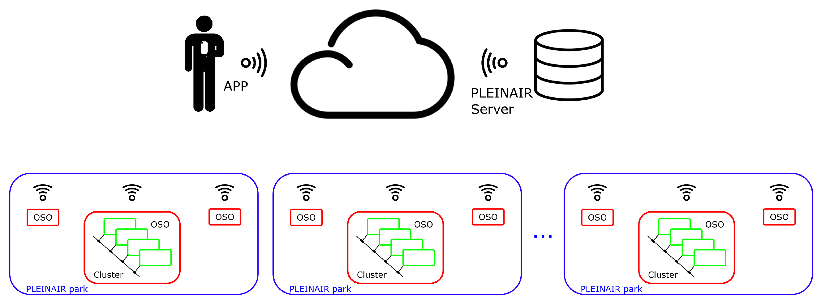
- A cloud-based architecture is exploited for data collection and interfacing to healthcare systems, caregivers, and users through different fashions. However, cloud interaction is subject to timing and network availability issues, which makes it unpractical to manage full control of smart tiles at the cloud level. Hence, a hierarchical approach is to be followed, with system intelligence distributed at different levels: a local control unit, needed for managing cloud communication, is in charge of fast response tasks, related for instance to the game execution. A modular, scalable architecture has been devised, which is described in the following sections;
- The pressure-sensitive floor tiles lend themselves to further different applications, not necessarily related to walking and footsteps. A comprehensive review of aimed applications was carried out by the project team, including bio-mechanical engineers and physiotherapists, to set design specifications: among them, demanding constraints were assumed in terms of spatial resolution, time response, and pressure sensitivity. In particular, an activation threshold of 300 g/tile was assumed: even though it largely exceeds the needs for footstep recognition, such high sensitivity is required to enable different applications. For instance, the sensitive tile was used for implementing games to improve hand coordination skills, aimed primarily at people with disabilities. Similarly, an optimal time resolution of 10 ms was specified, to ensure adequate game promptness;
- The aimed outdoor deployment introduces a set of additional constraints, in terms of robustness, installation techniques, waterproofness, power sourcing, etc. The engineering phase, strictly related to device production, is still to be completed, however. For the sake of conciseness, the technicalities related to such constraints are not fully discussed in the following.
2.2. The Smart Flooring System
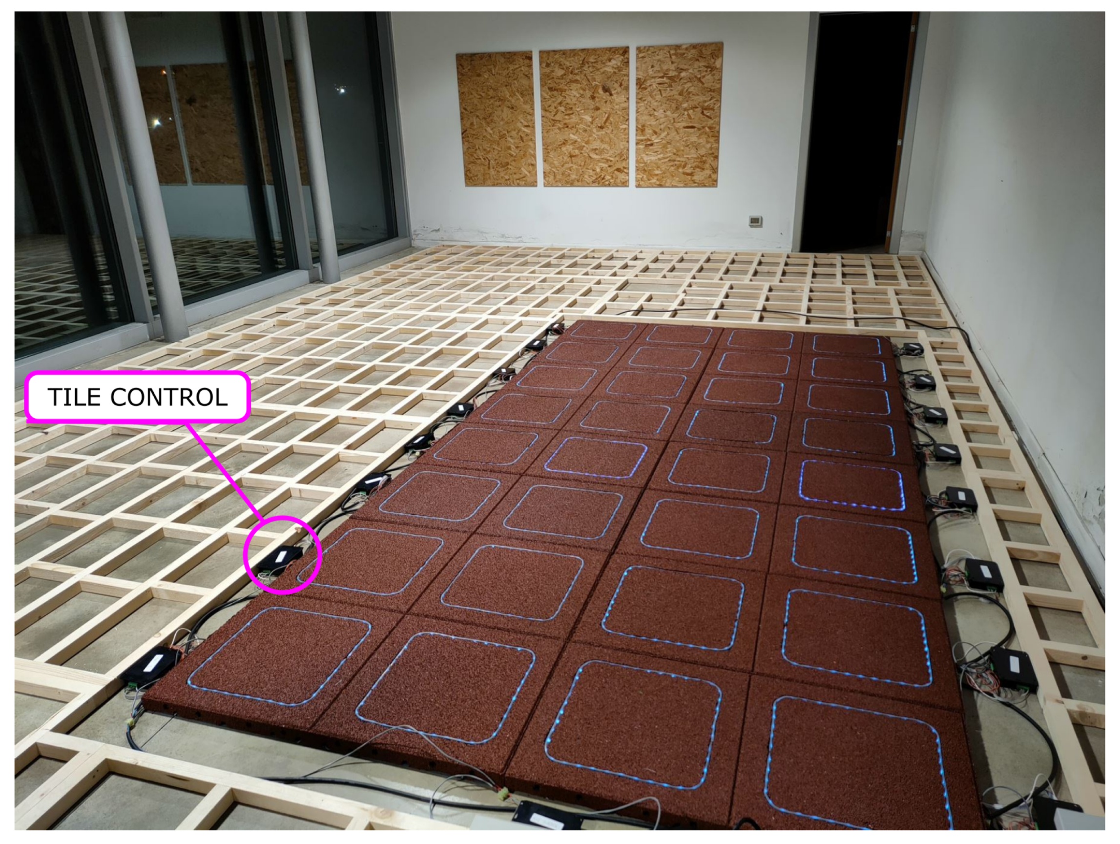
- Anti-trauma tiles (brown squares);
- Embedded piezoresistive sensors (yellow circles);
- LED strips (light blue square lines);
- Tile Remote Input/Output boards (RIO, red boxes);
- Game controller and Wi-Fi communication unit (control, blue box);
- User app, connecting to the cloud. Different apps can be envisaged, supporting different roles, i.e., park user, caregivers, GP’s, healthcare system, etc.

2.2.1. Smart Tiles
2.2.2. Mechanical Structure
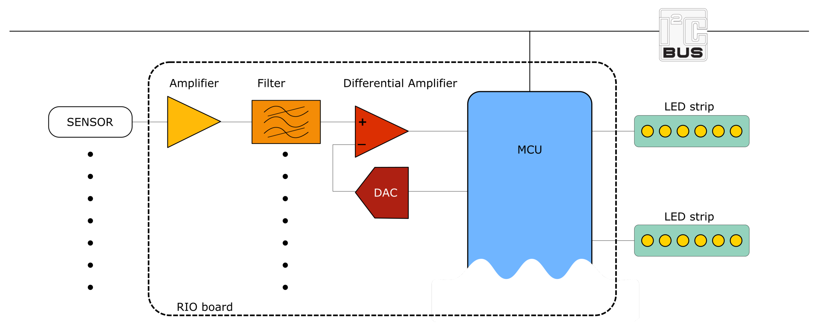
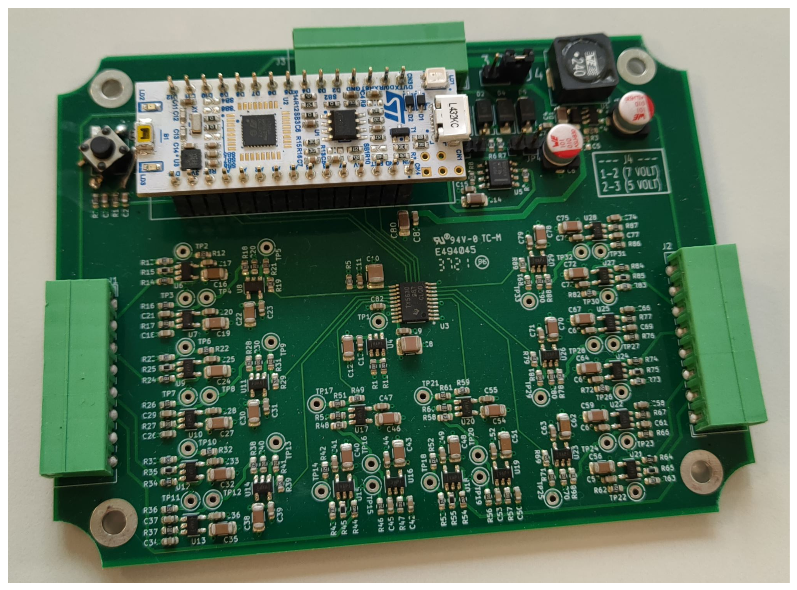
2.2.3. Electronic System
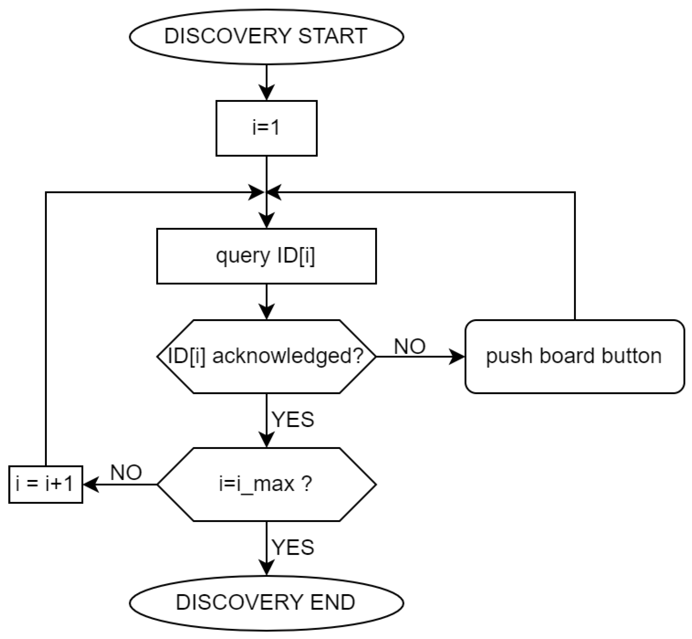
2.2.4. Communication Infrastructure and Configuration Procedure
2.2.5. Cloud Architecture and Game Execution
3. Characterization and Test
3.1. Description of the Experimental Setup
3.2. Experimental Results
4. Discussion
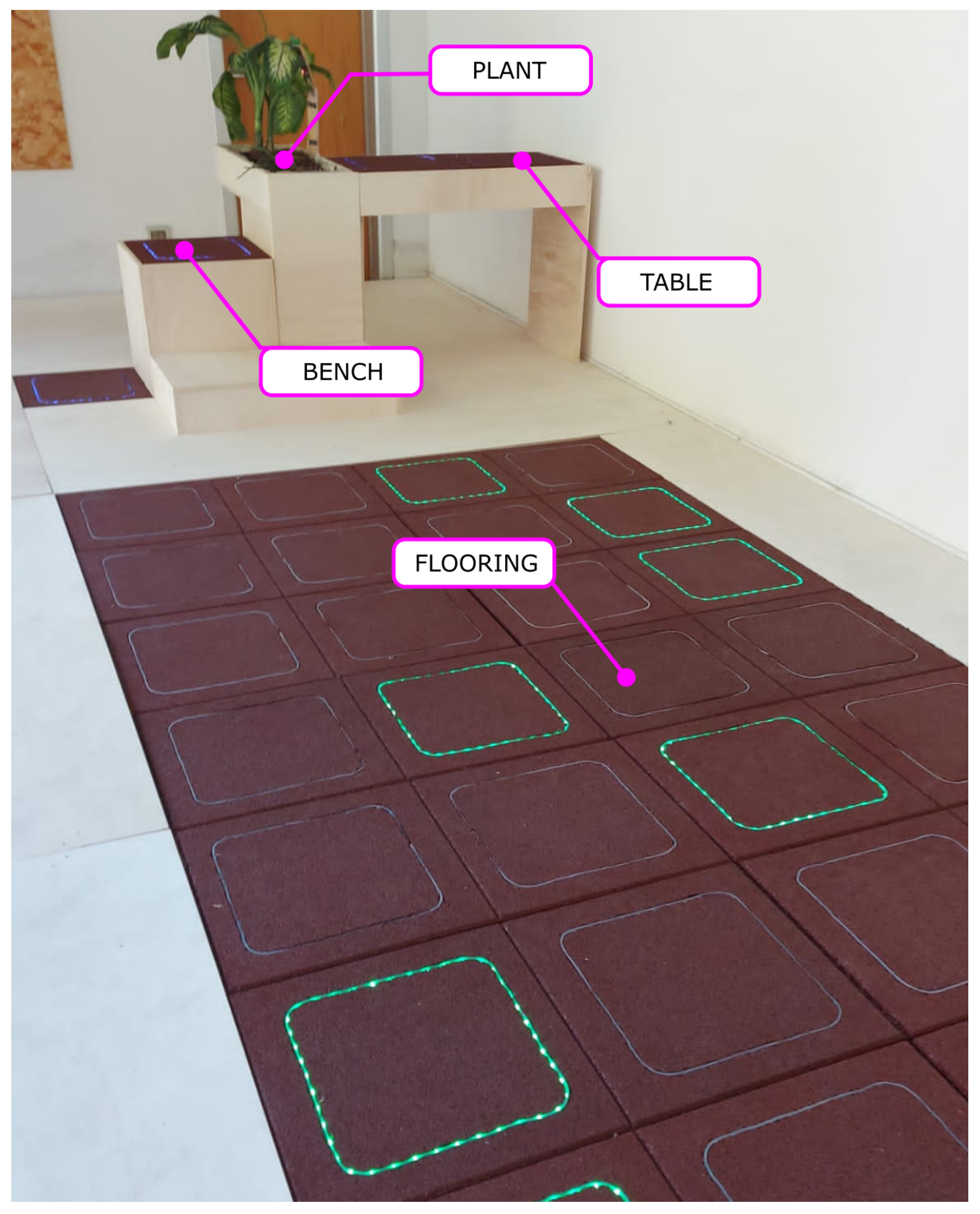
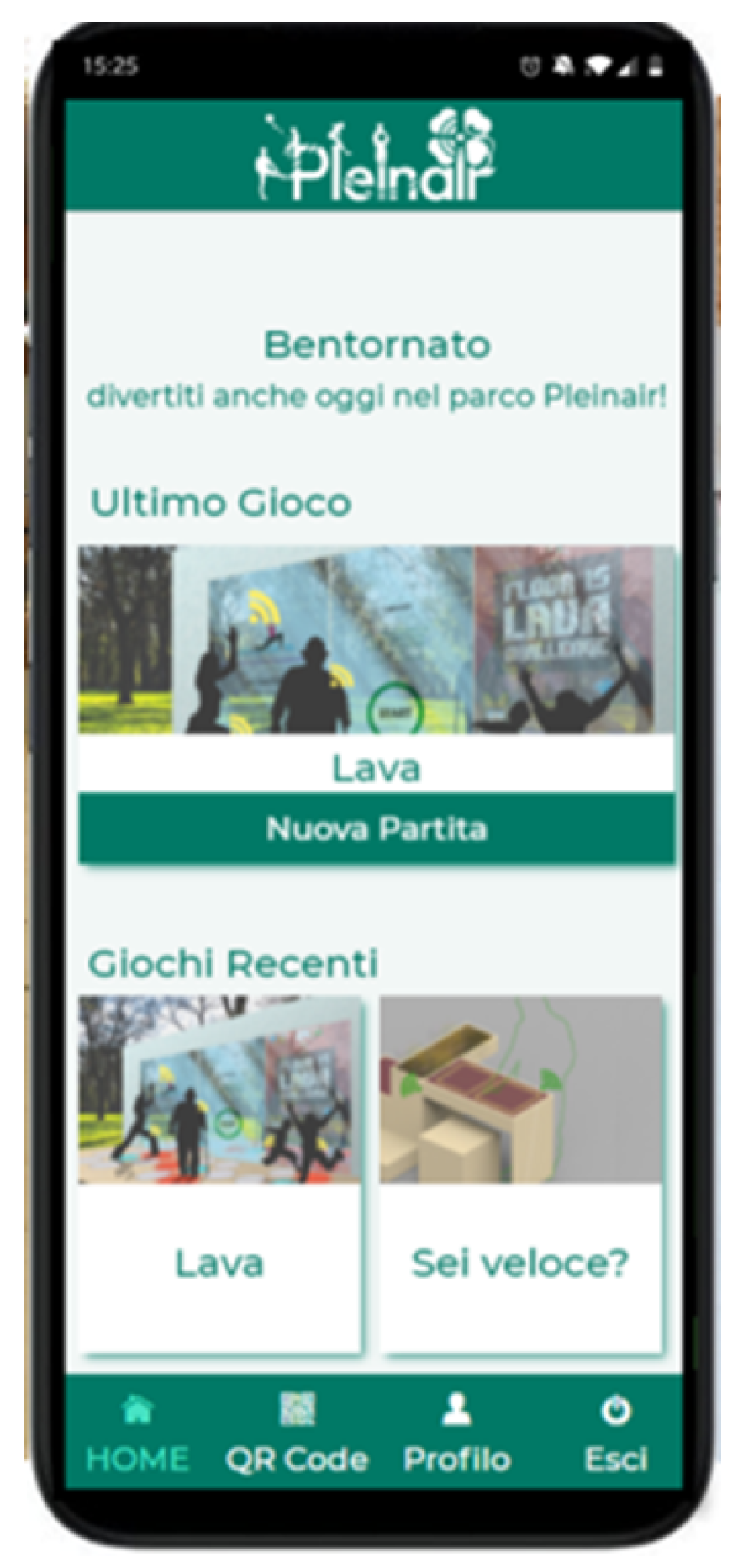
- Smart flooring: a 4 m × 2 m sensitive flooring, with 32 smart tiles covering the 8 m2 surface. The demo game required the user to follow a random path, indicated by the tiles lighting up in a sequence. If an out-of-sequence tile is stepped on, the user gets penalty points. The game is initiated by the web app (a screenshot, which is shown in Figure 13), and features different difficulty levels, based on the user’s profile. The overall score comes from the speed in completing the path and from the penalties for incorrect sequences;
- Smart bench: a sensorized stepper, exploiting two tiles. One tile is embedded in the seat, and the other one is on the pavement. A random sequence of activation is generated, with the user being asked to stand up and sitaccording to the colour code shown by the floor tile. The game stimulates strength, promptness, and coordination. It is controlled by the same web app: users were given a tablet to choose and start any of the available four games;
- Smart table: the table surface is made up of a couple of smart tiles, and the user is asked to press each tile with their hands when prompted by the colour code displayed by each tile. This game stimulates promptness and coordination, and was especially conceived for people with motor disabilities: the table structure was designed to allow for a wheelchair user to get close to the table surface. The high sensitivity of the tiles (as mentioned, a weight as small as 300 g can be detected) was fully exploited in this case, allowing people with weak upper limbs to enjoy the game;
- Smart planter: it is meant to demonstrate the flexibility and generality of the control architecture. In this case, no smart tiles were involved: the aim of the “game” was the remote control of a green plant, by monitoring environmental parameters such as temperature, humidity, atmospheric pressure, soil moisture, and allowing to manage additional lighting through a LED source. Despite the different purposes, the same general architecture and web app was used in this case too.
- Despite its rough and non-homogeneous texture, the adoption of the standard anti-trauma rubber mats was eventually feasible, this contributing to keeping a familiar look and feel for the OSOs and perspectively allowing for deployment in many scenarios;
- By leveraging the gaming aspects, the goal of stimulating PA was attained; the test involved different class ages, ranging from primary school pupils to elderly association members. Through personalization, such users were able to find motivation and reward, regardless of their age and physical fitness;
- A general-purpose IoT architecture has been devised and implemented, suitable for scaling up and for a much wider scope than that involved in the demonstration.
5. Conclusions
Author Contributions
Funding
Institutional Review Board Statement
Informed Consent Statement
Data Availability Statement
Acknowledgments
Conflicts of Interest
Abbreviations
| PA | Physical Activity |
| ICT | Information and Communication Technologies |
| AAL | Ambient and Assisted Living |
| OSO | Outdoor Smart Object |
References
- World Health Organization. Global Status Report on Physical Activity 2022. Available online: https://www.who.int/publications/i/item/9789240059153 (accessed on 1 January 2023).
- Chaparro, J.D.; Ruiz, J.F.B.; Romero, M.J.S.; Peño, C.B.; Irurtia, L.U.; Perea, M.G.; Garcia, X.d.T.; Molina, F.J.V.; Grigoleit, S.; Lopez, J.C. The shapes smart mirror approach for independent living, healthy and active ageing. Sensors 2021, 21, 7938. [Google Scholar] [CrossRef] [PubMed]
- Brunete, A.; Gambao, E.; Hernando, M.; Cedazo, R. Smart assistive architecture for the integration of IoT devices, robotic systems, and multimodal interfaces in healthcare environments. Sensors 2021, 21, 2212. [Google Scholar] [CrossRef] [PubMed]
- Grguric, A.; Khan, O.; Ortega-Gil, A.; Markakis, E.K.; Pozdniakov, K.; Kloukinas, C.; Medrano-Gil, A.M.; Gaeta, E.; Fico, G.; Koloutsou, K. Reference architectures, platforms, and pilots for european smart and healthy living—Analysis and comparison. Electronics 2021, 10, 1616. [Google Scholar] [CrossRef]
- Bechtold, U.; Stauder, N.; Fieder, M. Let’s walk it: Mobility and the perceived quality of life in older adults. Int. J. Environ. Res. Public Health 2021, 18, 11515. [Google Scholar] [CrossRef]
- Errico, V.; Ricci, M.; Pallotti, A.; Giannini, F.; Saggio, G. Ambient assisted living for tetraplegic people by means of an electronic system based on a novel sensory headwear: Increased possibilities for reduced abilities. In Proceedings of the 2018 IEEE International Symposium on Medical Measurements and Applications (MeMeA), Rome, Italy, 11–13 June 2018; pp. 1–6. [Google Scholar] [CrossRef]
- Mancini, A.; Frontoni, E.; Zingaretti, P. Embedded Multisensor System for Safe Point-to-Point Navigation of Impaired Users. IEEE Trans. Intell. Transp. Syst. 2015, 16, 3543–3555. [Google Scholar] [CrossRef]
- Stojanova, A.; Koceski, S.; Koceska, N. Continuous Blood Pressure Monitoring as a Basis for Ambient Assisted Living (AAL)—Review of Methodologies and Devices. J. Med. Syst. 2019, 43, 24. [Google Scholar] [CrossRef]
- Dionisi, A.; Marioli, D.; Sardini, E.; Serpelloni, M. Autonomous Wearable System for Vital Signs Measurement With Energy-Harvesting Module. IEEE Trans. Instrum. Meas. 2016, 65, 1423–1434. [Google Scholar] [CrossRef]
- Mora, N.; Cocconcelli, F.; Matrella, G.; Ciampolini, P. Accurate Heartbeat Detection on Ballistocardiogram Accelerometric Traces. IEEE Trans. Instrum. Meas. 2020, 69, 9000–9009. [Google Scholar] [CrossRef]
- Carek, A.M.; Jung, H.; Inan, O.T. A Reflective Photoplethysmogram Array and Channel Selection Algorithm for Weighing Scale Based Blood Pressure Measurement. IEEE Sens. J. 2020, 20, 3849–3858. [Google Scholar] [CrossRef]
- Ando, B.; Baglio, S.; Lombardo, C.O.; Marletta, V. An Event Polarized Paradigm for ADL Detection in AAL Context. IEEE Trans. Instrum. Meas. 2015, 64, 1814–1825. [Google Scholar] [CrossRef]
- Naranjo-Hernandez, D.; Roa, L.M.; Reina-Tosina, J.; Estudillo-Valderrama, M.A. SoM: A Smart Sensor for Human Activity Monitoring and Assisted Healthy Ageing. IEEE Trans. Biomed. Eng. 2012, 59, 3177–3184. [Google Scholar] [CrossRef] [PubMed]
- Wang, Z.; Yang, Z.; Dong, T. A Review of Wearable Technologies for Elderly Care that Can Accurately Track Indoor Position, Recognize Physical Activities and Monitor Vital Signs in Real Time. Sensors 2017, 17, 341. [Google Scholar] [CrossRef] [PubMed] [Green Version]
- Madureira, P.; Cardoso, N.; Sousa, F.; Moreira, W.; Oliveira, A., Jr.; Bazzani, M.; Gouverneur, P. My-AHA: Software Platform to Promote Active and Healthy Ageing. Information 2020, 11, 438. [Google Scholar] [CrossRef]
- Mora, N.; Matrella, G.; Ciampolini, P. Cloud-Based Behavioral Monitoring in Smart Homes. Sensors 2018, 18, 1951. [Google Scholar] [CrossRef] [Green Version]
- PLEINAIR Official Website. Available online: https://www.pleinairpark.it/ (accessed on 1 December 2022).
- Mincolelli, G.; Giacobone, G.A.; Imbesi, S.; Marchi, M. Human centered design methodologies applied to complex research projects: First results of the PLEINAIR project. In Proceedings of the International Conference on Applied Human Factors and Ergonomics, Virtual, 16–20 July 2020; Springer: Berlin/Heidelberg, Germany, 2020; pp. 3–9. [Google Scholar]
- Orr, R.J.; Abowd, G.D. The smart-flooring. In Proceedings of the CHI ’00 Extended Abstracts on Human Factors in Computing Systems–CHI ’00, New Orleans, LA, USA, 29 April–5 May 2000; ACM Press: New York, NY, USA, 2000; p. 275. [Google Scholar] [CrossRef]
- Addlesee, M.; Jones, A.; Livesey, F.; Samaria, F. The ORL active floor [sensor system]. IEEE Pers. Commun. 1997, 4, 35–41. [Google Scholar] [CrossRef]
- Serra, R.; Knittel, D.; Di Croce, P.; Peres, R. Activity Recognition With Smart Polymer Floor Sensor: Application to Human Footstep Recognition. IEEE Sens. J. 2016, 16, 5757–5775. [Google Scholar] [CrossRef]
- Tošić, A.; Hrovatin, N.; Vičič, J. A WSN Framework for Privacy Aware Indoor Location. Appl. Sci. 2022, 12, 3204. [Google Scholar] [CrossRef]
- Chang, S.; Ham, S.; Kim, S.; Suh, D.; Kim, H. Ubi-Floor: Design and Pilot Implementation of an Interactive Floor System. In Proceedings of the 2010 Second International Conference on Intelligent Human-Machine Systems and Cybernetics, Nanjing, China, 26–28 August 2010; pp. 290–293. [Google Scholar] [CrossRef]
- Zhao, Y.; Tian, B.; Niu, Y.; Zhang, H.; Yi, Z.; Zeng, R. A Security Management and Control Solution of Smart Park Based on Sensor Networks. Sensors 2021, 21, 6815. [Google Scholar] [CrossRef]
- Faulkner, N.; Parr, B.; Alam, F.; Legg, M.; Demidenko, S. CapLoc: Capacitive Sensing Floor for Device-Free Localization and Fall Detection. IEEE Access 2020, 8, 187353–187364. [Google Scholar] [CrossRef]
- Arshad, A.; Khan, S.; Alam, A.H.M.Z.; Ismail, A.F.; Tasnim, R. Capacitive proximity floor sensing system for elderly tracking and fall detection. In Proceedings of the 2017 IEEE 4th International Conference on Smart Instrumentation, Measurement and Application (ICSIMA), Kuala Lumpur, Malaysia, 28–30 November 2017; pp. 1–5. [Google Scholar] [CrossRef]
- Muheidat, F.; Tawalbeh, L.A. In-Home Floor Based Sensor System-Smart Carpet- to Facilitate Healthy Aging in Place (AIP). IEEE Access 2020, 8, 178627–178638. [Google Scholar] [CrossRef]
- Liau, W.H.; Wu, C.L.; Fu, L.C. Inhabitants Tracking System in a Cluttered Home Environment Via Floor Load Sensors. IEEE Trans. Autom. Sci. Eng. 2008, 5, 10–20. [Google Scholar] [CrossRef]
- Al-Naimi, I.; Wong, C.B.; Moore, P.; Chen, X. Advanced approach for indoor identification and tracking using smart-flooring and pyroelectric infrared sensors. In Proceedings of the 2014 5th International Conference on Information and Communication Systems (ICICS), Irbid, Jordan, 1–3 April 2014; pp. 1–6. [Google Scholar] [CrossRef]
- Feng, G.; Yang, Y.; Guo, X.; Wang, G. A Smart Fiber Floor for Indoor Target Localization. IEEE Pervasive Comput. 2015, 14, 52–59. [Google Scholar] [CrossRef]
- Jintanawan, T.; Phanomchoeng, G.; Suwankawin, S.; Kreepoke, P.; Chetchatree, P.; U-viengchai, C. Design of Kinetic-Energy Harvesting Floors. Energies 2020, 13, 5419. [Google Scholar] [CrossRef]
- He, C.; Zhu, W.; Chen, B.; Xu, L.; Jiang, T.; Han, C.B.; Gu, G.Q.; Li, D.; Wang, Z.L. Smart-Flooring with Integrated Triboelectric Nanogenerator as Energy Harvester and Motion Sensor. ACS Appl. Mater. Interfaces 2017, 9, 26126–26133. [Google Scholar] [CrossRef] [PubMed]
- Shi, Q.; Zhang, Z.; He, T.; Sun, Z.; Wang, B.; Feng, Y.; Shan, X.; Salam, B.; Lee, C. Deep learning enabled smart mats as a scalable floor monitoring system. Nat. Commun. 2020, 11, 4609. [Google Scholar] [CrossRef]
- Contigiani, M.; Frontoni, E.; Mancini, A.; Gatto, A. Indoor people localization and tracking using an energy harvesting smart-flooring. In Proceedings of the 2014 IEEE/ASME 10th International Conference on Mechatronic and Embedded Systems and Applications (MESA), Senigallia, Italy, 10–12 October 2014; pp. 1–5. [Google Scholar] [CrossRef]
- Visconti, P.; Bagordo, L.; Velázquez, R.; Cafagna, D.; De Fazio, R. Available Technologies and Commercial Devices to Harvest Energy by Human Trampling in Smart Flooring Systems: A Review. Energies 2022, 15, 432. [Google Scholar] [CrossRef]
- Hu, R.; Michel, B.; Russo, D.; Mora, N.; Matrella, G.; Ciampolini, P.; Cocchi, F.; Montanari, E.; Nunziata, S.; Brunschwiler, T. An unsupervised behavioral modeling and alerting system based on passive sensing for elderly care. Future Internet 2020, 13, 6. [Google Scholar] [CrossRef]
- Arcelus, A.; Herry, C.L.; Goubran, R.A.; Knoefel, F.; Sveistrup, H.; Bilodeau, M. Determination of Sit-to-Stand Transfer Duration Using Bed and Floor Pressure Sequences. IEEE Trans. Biomed. Eng. 2009, 56, 2485–2492. [Google Scholar] [CrossRef]
- Espinilla, M.; Medina, J.; Nugent, C. UCAmI Cup. Analyzing the UJA Human Activity Recognition Dataset of Activities of Daily Living. Proceedings 2018, 2, 1267. [Google Scholar] [CrossRef] [Green Version]
- Jiménez, A.; Seco, F. Event-Driven Real-Time Location-Aware Activity Recognition in AAL Scenarios. Proceedings 2018, 2, 1240. [Google Scholar] [CrossRef] [Green Version]
- Cerón, J.D.; López, D.M.; Eskofier, B.M. Human Activity Recognition Using Binary Sensors, BLE Beacons, an Intelligent Floor and Acceleration Data: A Machine Learning Approach. Proceedings 2018, 2, 1265. [Google Scholar] [CrossRef] [Green Version]
- Granell, C.; Kamilaris, A.; Kotsev, A.; Ostermann, F.O.; Trilles, S. Internet of Things. In Manual of Digital Earth; Guo, H., Goodchild, M.F., Annoni, A., Eds.; Springer: Singapore, 2020; pp. 387–423. [Google Scholar] [CrossRef] [Green Version]
- Trilles, S.; Torres-Sospedra, J.; Belmonte, Ó.; Zarazaga-Soria, F.J.; González-Pérez, A.; Huerta, J. Development of an open sensorized platform in a smart agriculture context: A vineyard support system for monitoring mildew disease. Sustain. Comput. Inform. Syst. 2020, 28, 100309. [Google Scholar] [CrossRef]
- PLEINAIR Video Description. Available online: https://www.youtube.com/watch?v=Yr_0RcdNOjE/ (accessed on 1 December 2022).
- PLEINAIR Partners List. Available online: https://www.pleinairpark.it/partner-imprese-pleinair/ (accessed on 1 December 2022).


Disclaimer/Publisher’s Note: The statements, opinions and data contained in all publications are solely those of the individual author(s) and contributor(s) and not of MDPI and/or the editor(s). MDPI and/or the editor(s) disclaim responsibility for any injury to people or property resulting from any ideas, methods, instructions or products referred to in the content. |
© 2023 by the authors. Licensee MDPI, Basel, Switzerland. This article is an open access article distributed under the terms and conditions of the Creative Commons Attribution (CC BY) license (https://creativecommons.org/licenses/by/4.0/).
Share and Cite
Cocconcelli, F.; Matrella, G.; Mora, N.; Casu, I.; Vargas Godoy, D.A.; Ciampolini, P. IoT Smart Flooring Supporting Active and Healthy Lifestyles. Sensors 2023, 23, 3162. https://doi.org/10.3390/s23063162
Cocconcelli F, Matrella G, Mora N, Casu I, Vargas Godoy DA, Ciampolini P. IoT Smart Flooring Supporting Active and Healthy Lifestyles. Sensors. 2023; 23(6):3162. https://doi.org/10.3390/s23063162
Chicago/Turabian StyleCocconcelli, Federico, Guido Matrella, Niccolò Mora, Ion Casu, David Alejandro Vargas Godoy, and Paolo Ciampolini. 2023. "IoT Smart Flooring Supporting Active and Healthy Lifestyles" Sensors 23, no. 6: 3162. https://doi.org/10.3390/s23063162