

PALANTIR: An NFV-Based Security-as-a-Service Approach for Automating Threat Mitigation
 , ,
, ,  , , , , , and
Abstract
:1. Introduction
1.1. Motivations
1.2. Contributions
1.3. Benefits
1.4. Organisation
2. Related Work
2.1. NFV Usage for Cybersecurity
2.2. Policy-Driven Security Management
2.3. Security Enforcement
3. Motivating Cases
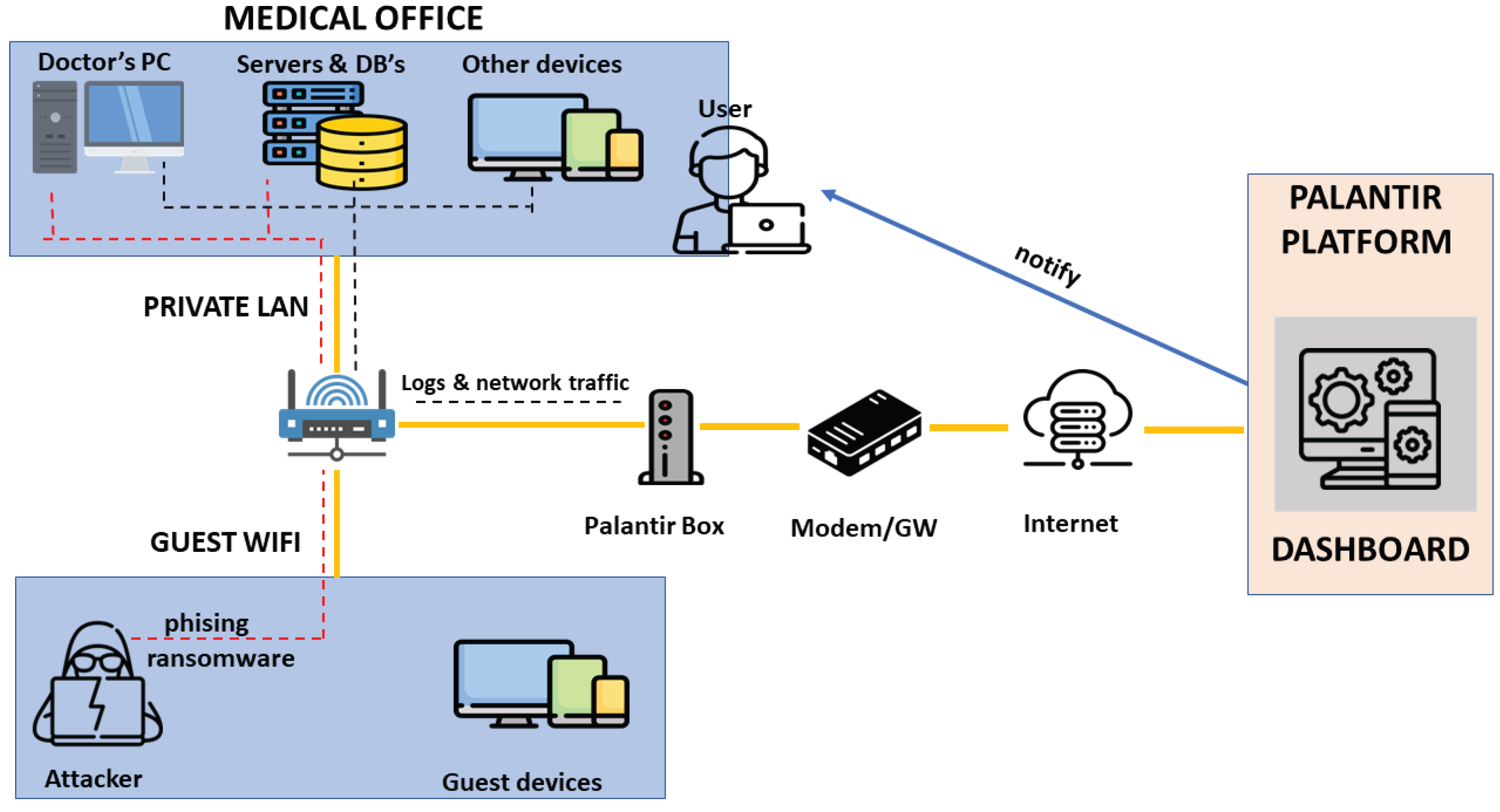
3.1. Use Case 1: Protection of the E-Health Environment
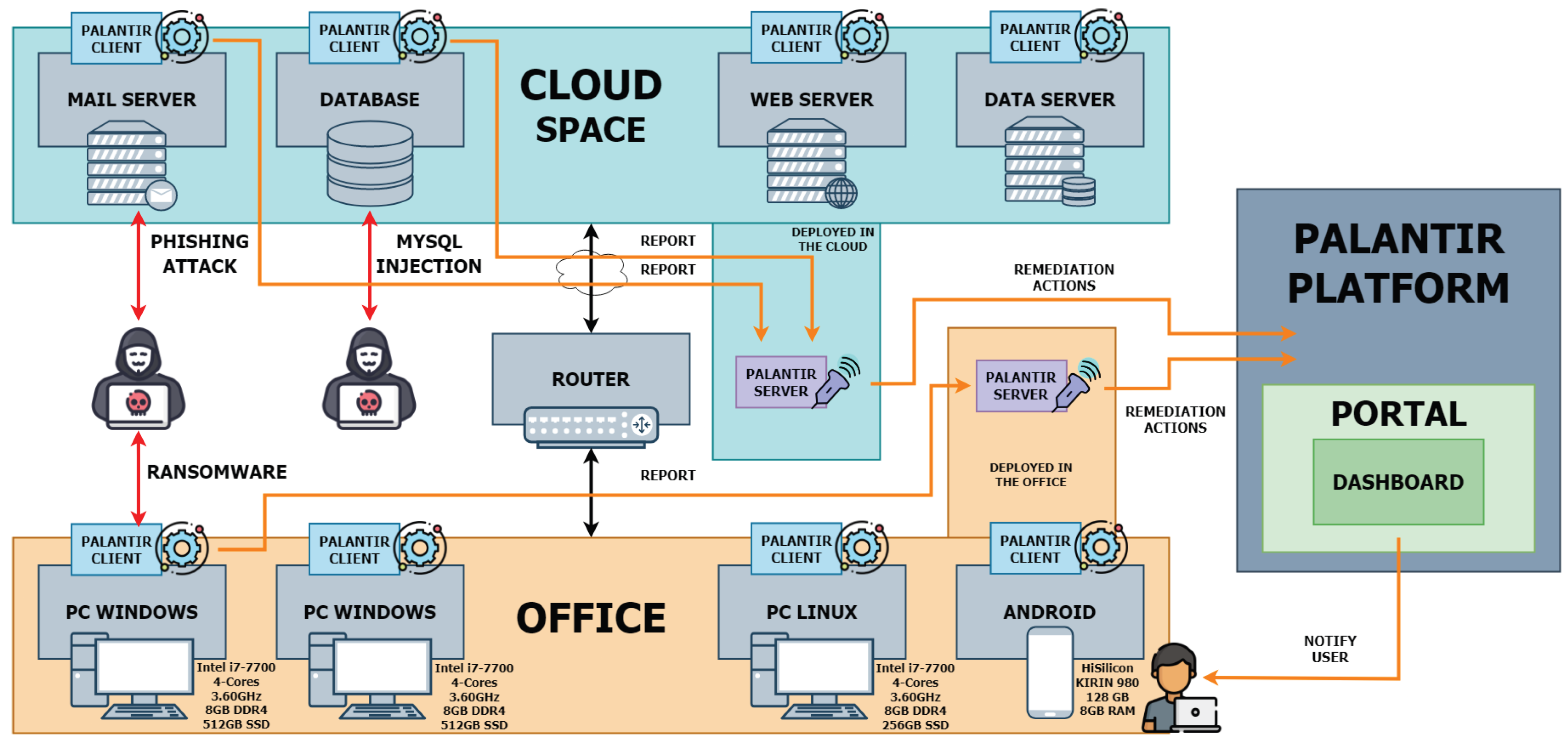
3.2. Use Case 2: Resilience of the E-Commerce Platform
3.3. Requirements of Remediation Procedures
4. PALANTIR General Architecture for Threat Remediation
4.1. Overview of the Architecture
4.2. Coordination of the Remediation Procedure
4.3. Selection of the Security Capabilities
4.4. Availability of the Security Capabilities
4.5. Orchestration of the Security Enablers
4.6. Design and Operation of Security Enablers
4.7. Remediation Awareness
4.8. Deployment Models
- Central layer: First, and common to all deployment models, the upper, central layer introduces the PALANTIR components that have some degree of observation of the overall procedures, e.g., those requiring support for multi-tenancy (both regarding customers, as organisations, and their infrastructures). These are the Portal, the SCC, the SM, and the SO.
- Processing layer: In contrast, the lower, processing layer shows the components running at a site local to or near the deployment infrastructure, used to instantiate the SCs and to operate closer to the infrastructure and captured data. These include the IR, the SCHI, the deployed SCs, and other components of the PALANTIR framework that are not described in this work.
5. Data Modelling
5.1. Ontology
- The Data Type represents the different data modalities contemplated in PALANTIR (e.g., NetFlow and Zeek data).This class is connected to the Protection Method, and uses the latter as input.
- The Protection Method class defines the detection and mitigation methods (i.e., the two types of available protection) as its subclasses.It is connected to two specific classes: Security Capability and Threat.
- The Security Capability class is the formal name for the security mechanisms, and it refers to the virtual element developed to be deployed in the client infrastructure.This class supposes a central part of the ontology because it has a relationship with a large portion of the ontology classes. Section 5.5 delves into details about the properties and metadata modelling this class. In addition, a Security Capability can implement one or more protection methods and is related to the Threat class, contributing to mitigate the effects represented by the latter.
- The Threat class defines the threats/attacks following the indications of threat modelling methodologies such as OCTAVE [53] and STRIDE [54], well-known tools for representing such types of activities.This class is also connected to the Billing Model and Incident Response classes because it directly affects the data allocated among both classes.
- One the one hand, the Billing Model class represents the different fees to be applied regarding the deployed SCs and the contracted characteristics.The connection between the Billing Model and Threat classes is due to a Threat generating a remediation procedure that deploys a new security mechanism. This fact is also represented by the connection between the Billing Model, Incident Response, and Security Capability classes.
- In addition, the Billing Model depends on the Deployment Model; the latter defines the deployment models available, which have associated different physical resources, operation modes, etc.
- Finally, the Incident Response class models the element selecting and performing the remediation procedures when a threat/attack is detected.Therefore, it connects with the Threat and Billing Model classes, already described, but also with the Security Capability class, since the remediation procedure to be performed can result in the reconfiguration of a security mechanism deployed in the client infrastructure.
5.2. Remediation Policy
5.3. Constraint Satisfaction Problem for Enabler Selection
5.3.1. Infrastructure-Issued Constraints
- indicates the amount of CPU needed on infrastructure if deployment configuration is enacted;
- states the amount of RAM needed;
- stands for the required storage capacity.
5.3.2. Security-Capability-Issued Constraints
5.3.3. Construction of a Cost Function
5.4. Billing Models for SecaaS Operation
- On-subscription billing: the first deployment of a mechanism results in the subscription of a general licence at a fixed cost; further deployments will not induce further payments.
- On-instantiation billing: each time a mechanism is scheduled for deployment, the fixed cost is charged.
- Operation billing: when a mechanism is deployed, a cost proportional to its operation duration is charged.
5.5. Security Capability Entry Model
- Qualification of relevant SC: PALANTIR defines some fields to classify the type of SC to make clear decisions as to where a new SC must be deployed, derived from the ontology presented in Section 5.1. These are detection-method, mitigation-method, control-data-type, and monitor-data-type.
- Billing of SC usage: To define the requirements presented in Section 5.4, PALANTIR proposes billing_model, subscription_billing, instance_billing, and hourly_billing fields. Each SC has associated a different cost and a billing model regarding its capacities and characteristics.
- Assessment of the service-level agreement: In this case, PALANTIR categorises the SCs with their service-level agreement applied and the violation fee associated. For this, sla and sla_violation_fee fields are added.
- Support for multiple deployment models: The SC entry includes some fields to indicate the supported deployment model(s), and the resources needed to the correct SC operation. Therefore, the fields deployment_model, nbCpu, amountRam, and amountStg are defined.
6. Validation
6.1. Testbed Environment
6.1.1. Use Case 1: On-Premises Testbed for E-Health Environment
6.1.2. Use Case 2: Cloud Testbed for E-Commerce Platform
6.2. Qualitative Evaluation
6.2.1. Incident Response Prototype Implementation
6.2.2. Service Matching Prototype Implementation
6.2.3. Security Capability Catalogue Prototype Implementation
6.2.4. Security Orchestrator Prototype Implementation
6.2.5. Security Capability Prototype Implementation
6.2.6. Security Portal Prototype Implementation
6.3. Quantitative Evaluation
6.3.1. Performance Evaluation of the Security Capability Selection Process
6.3.2. Orchestration of Security Capabilities
7. Conclusions and Future Work
Author Contributions
Funding
Institutional Review Board Statement
Informed Consent Statement
Data Availability Statement
Conflicts of Interest
References
- 2022 Global Threat Report. Available online: https://www.crowdstrike.com/global-threat-report (accessed on 11 January 2023).
- SMBs Are Fighting against All Odds in Today’s Cyber Landscape. Available online: https://pages.checkpoint.com/smb-2021-security-report.html (accessed on 11 January 2023).
- Managing the Trend of Growing IT Complexity. Available online: https://mysecuritymarketplace.com/reports/managing-the-trend-of-growing-it-complexity (accessed on 11 January 2023).
- 2021 DBIR Master’s Guide. Available online: https://www.verizon.com/business/resources/reports/dbir/2021/masters-guide/ (accessed on 11 January 2023).
- Blanco, B.; Fajardo, J.O.; Giannoulakis, I.; Kafetzakis, E.; Peng, S.; Pérez-Romero, J.; Trajkovska, I.; Khodashenas, P.S.; Goratti, L.; Paolino, M.; et al. Technology Pillars in the Architecture of Future 5G Mobile Networks: NFV, MEC and SDN. Comput. Stand. Interfaces 2017, 54, 216–228. [Google Scholar] [CrossRef]
- Mantas, E.; Papadopoulos, D.; Fernández, C.; Ortiz, N.; Compastié, M.; López Martínez, A.; Gil Pérez, M.; Kourtis, A.; Xylouris, G.; Mlakar, I.; et al. Practical Autonomous Cyberhealth for Resilient Micro, Small and Medium-sized Enterprises. In Proceedings of the 2021 IEEE International Mediterranean Conference on Communications and Networking (MeditCom), Athens, Greece, 7–10 September 2021; pp. 500–505. [Google Scholar]
- López Martínez, A.; Zago, M.; Gil Pérez, M. Provision of Security-as-a-Service (SecaaS) in Lightweight Scenarios. In Proceedings of the VII National Conference on Cybersecurity Research (JNIC), Bilbao, Spain, 27–29 June 2022; pp. 327–330. [Google Scholar]
- Hutchins, E.M.; Cloppert, M.J.; Amin, R.M. Intelligence-Driven Computer Network Defense Informed by Analysis of Adversary Campaigns and Intrusion Kill Chains. Available online: https://www.lockheedmartin.com/content/dam/lockheed-martin/rms/documents/cyber/LM-White-Paper-Intel-Driven-Defense.pdf (accessed on 11 January 2023).
- Diogenes, Y.; Ozkaya, E. Cybersecurity–Attack and Defense Strategies: Improve Your Security Posture to Mitigate Risks and Prevent Attackers from Infiltrating Your System, 3rd ed.; Packt Publishing Ltd.: Birmingham, UK, 2022; ISBN 9781803248776. [Google Scholar]
- Network Functions Virtualisation (NFV); Use Cases. Available online: https://www.etsi.org/deliver/etsi_gs/nfv/001_099/001/01.01.01_60/gs_nfv001v010101p.pdf (accessed on 11 January 2023).
- Network Functions Virtualisation (NFV); Architectural Framework. Available online: https://www.etsi.org/deliver/etsi_gs/nfv/001_099/002/01.02.01_60/gs_nfv002v010201p.pdf (accessed on 11 January 2023).
- Sciancalepore, V.; Yousaf, F.Z.; Costa-Perez, X. z-TORCH: An Automated NFV Orchestration and Monitoring Solution. IEEE Trans. Netw. Serv. Manag. 2018, 15, 1292–1306. [Google Scholar] [CrossRef]
- Kourtis, M.A.; McGrath, M.J.; Gardikis, G.; Xilouris, G.; Riccobene, V.; Papadimitriou, P.; Trouva, E.; Liberati, F.; Trubian, M.; Batallé, J.; et al. T-NOVA: An Open-Source MANO Stack for NFV Infrastructures. IEEE Trans. Netw. Serv. Manag. 2017, 14, 586–602. [Google Scholar] [CrossRef]
- Riggio, R.; Khan, S.N.; Subramanya, T.; Yahia, I.G.B.; Lopez, D. LightMANO: Converging NFV and SDN at the Edges of the Network. In Proceedings of the 2018 IEEE/IFIP Network Operations and Management Symposium, Taipei, Taiwan, 23–27 April 2018; pp. 1–9. [Google Scholar]
- Gharbaoui, M.; Contoli, C.; Davoli, G.; Borsatti, D.; Cuffaro, G.; Paganelli, F.; Cerroni, W.; Cappanera, P.; Martini, B. An Experimental Study on Latency-Aware and Self-Adaptive Service Chaining Orchestration in Distributed NFV and SDN Infrastructures. Comput. Netw. 2022, 208, 108880. [Google Scholar] [CrossRef]
- He, M.; Basta, A.; Blenk, A.; Deric, N.; Kellerer, W. P4NFV: An NFV Architecture with Flexible Data Plane Reconfiguration. In Proceedings of the 2018 14th International Conference on Network and Service Management (CNSM), Rome, Italy, 5–9 November 2018. [Google Scholar]
- Sanchez-Aguero, V.; Vidal, I.; Valera, F.; Nogales, B.; Mendes, L.L.; Damascena Dias, W.; Carvalho Ferreira, A. Deploying an NFV-Based Experimentation Scenario for 5G Solutions in Underserved Areas. Sensors 2021, 21, 1897. [Google Scholar] [CrossRef] [PubMed]
- Dhakal, A.; Ramakrishnan, K.K. NetML: An NFV Platform with Efficient Support for Machine Learning Applications. In Proceedings of the 2019 IEEE Conference on Network Softwarization (NetSoft), Paris, France, 24–28 June 2019; pp. 396–404. [Google Scholar]
- Gardikis, G.; Tzoulas, K.; Tripolitis, K.; Bartzas, A.; Costicoglou, S.; Lioy, A.; Gaston, B.; Fernandez, C.; Davila, C.; Litke, A.; et al. SHIELD: A Novel NFV-Based Cybersecurity Framework. In Proceedings of the 2017 IEEE Conference on Network Softwarization (NetSoft), Bologna, Italy, 3–7 July 2017; IEEE: Bologna, Italy, 2017; pp. 1–6. [Google Scholar]
- Pattaranantakul, M.; He, R.; Meddahi, A.; Zhang, Z. SecMANO: Towards Network Functions Virtualization (NFV) Based Security MANagement and Orchestration. In Proceedings of the 2016 IEEE Trustcom/BigDataSE/ISPA, Tianjin, China, 23–26 August 2016; pp. 598–605. [Google Scholar]
- Dutta, A.; Sood, K.; Lu, W. Network Functions Virtualisation (NFV) Release 3; Security; Security Management and Monitoring Specification. Available online: https://www.etsi.org/deliver/etsi_gs/NFV-SEC/001_099/013/03.01.01_60/gs_NFV-SEC013v030101p.pdf (accessed on 11 January 2023).
- Duan, Q.; Wang, S.; Ansari, N. Convergence of Networking and Cloud/Edge Computing: Status, Challenges, and Opportunities. IEEE Netw. 2020, 34, 148–155. [Google Scholar] [CrossRef]
- Tsagkaropoulos, A.; Verginadis, Y.; Compastié, M.; Apostolou, D.; Mentzas, G. Extending TOSCA for Edge and Fog Deployment Support. Electronics 2021, 10, 737. [Google Scholar] [CrossRef]
- Compastié, M.; Badonnel, R.; Festor, O.; He, R. A TOSCA-Oriented Software-Defined Security Approach for Unikernel-Based Protected Clouds. In Proceedings of the 2019 IEEE Conference on Network Softwarization (NetSoft), Paris, France, 24–28 June 2019; pp. 151–159. [Google Scholar]
- Lodderstedt, T.; Basin, D.; Doser, J. SecureUML: A UML-Based Modeling Language for Model-Driven Security. In The Unified Modeling Language, Proceedings of the «UML» 2002, Dresden, Germany, 30 September–4 October 2002; Jézéquel, J.M., Hussmann, H., Cook, S., Eds.; Springer: Berlin/Heidelberg, Germany, 2002; pp. 426–441. [Google Scholar]
- Chowdhary, A.; Sabur, A.; Vadnere, N.; Huang, D. Intent-Driven Security Policy Management for Software-Defined Systems. IEEE Trans. Netw. Serv. Manag. 2022. Early Access. [Google Scholar] [CrossRef]
- Godik, S.; Moses, T.; Anderson, A.; Parducci, B.; Adams, C.; Flinn, D.; Brose, G.; Lockhart, H.; Beznosov, K.; Kudo, M.; et al. EXtensible Access Control Markup Language (XACML) Version 1.0; OASIS Standard: Manchester, UK, 2003. [Google Scholar]
- Sahay, R. Policy-Driven Autonomic Cyberdefense Using Software-Defined Networking. Ph.D. Thesis, Institut National des Télécommunications, Evry, France, 2017. Available online: https://tel.archives-ouvertes.fr/tel-01712306/document (accessed on 11 January 2023).
- Barrère, M.; Badonnel, R.; Festor, O. A SAT-Based Autonomous Strategy for Security Vulnerability Management. In Proceedings of the 2014 IEEE Network Operations and Management Symposium (NOMS), Krakow, Poland, 5–9 May 2014; pp. 1–9. [Google Scholar]
- Ullah, S.; Xuefeng, Z.; Feng, Z. TCloud: A Dynamic Framework and Policies for Access Control across Multiple Domains in Cloud Computing. Int. J. Comput. Appl. 2013, 62, 1–7. [Google Scholar] [CrossRef]
- Mozzaquatro, B.A.; Jardim-Goncalves, R.; Agostinho, C. Towards a Reference Ontology for Security in the Internet of Things. In Proceedings of the 2015 IEEE International Workshop on Measurements Networking (M N), Coimbra, Portugal, 12–13 October 2015; pp. 1–6. [Google Scholar]
- Preuveneers, D.; Joosen, W. Towards Multi-Party Policy-Based Access Control in Federations of Cloud and Edge Microservices. In Proceedings of the 2019 IEEE European Symposium on Security and Privacy Workshops (EuroS&PW), Stockholm, Sweden, 17–19 June 2019; pp. 29–38. [Google Scholar]
- Weissman, D.; Jayasumana, A. Integrating IoT Monitoring for Security Operation Center. In Proceedings of the 2020 Global Internet of Things Summit (GIoTS), virtual, 3 June 2020; pp. 1–6. [Google Scholar]
- Luo, S.; Salem, M.B. Orchestration of Software-Defined Security Services. In Proceedings of the 2016 IEEE International Conference on Communications Workshops (ICC), Kuala Lumpur, Malaysia, 23–27 May 2016; pp. 436–441. [Google Scholar]
- Compastié, M.; Badonnel, R.; Festor, O.; He, R.; Kassi-Lahlou, M. Towards a Software-Defined Security Framework for Supporting Distributed Cloud. In Proceedings of the 2017 IFIP International Conference on Autonomous Infrastructure, Management and Security (AIMS), Zurich, Switzerland, 10–13 July 2017; pp. 47–61. [Google Scholar]
- Lopez, D.; Lopez, E.; Dunbar, L.; Strassner, J.; Kumar, R. Framework for Interface to Network Security Functions. 2018, p. 25. Available online: https://datatracker.ietf.org/doc/rfc8329 (accessed on 11 January 2023).
- Gu, G.; Ott, D.; Sekar, V.; Sun, K.; Al-Shaer, E.; Cardenas, A.; Chen, Y.; Enck, W.; Hu, H.; Moreau, D.; et al. Programmable System Security in a Software-Defined World—Research Challenges and Opportunities. Available online: https://research.vmware.com/publications/programmable-system-security-in-a-software-defined-world-research-challenges-and-opportunities (accessed on 11 January 2023).
- Benzina, H. Enforcing Virtualized Systems Security. Ph.D. Thesis, École Normale supéRieure de Cachan—ENS Cachan, Cachan, France, 2012. Available online: https://tel.archives-ouvertes.fr/tel-00846513/document (accessed on 11 January 2023).
- Bélair, M.; Laniepce, S.; Menaud, J.M. SNAPPY: Programmable Kernel-Level Policies for Containers. In Proceedings of the 36th Annual ACM Symposium on Applied Computing, SAC ’21, virtual, 22–26 March 2021; Association for Computing Machinery: New York, NY, USA, 2021; pp. 1636–1645. [Google Scholar]
- Current and Emerging Healthcare Cyber Threat Landscape. Available online: https://h-isac.org/health-isacs-first-annual-current-and-emerging-healthcare-cyber-threat-landscape-executive-summary/ (accessed on 11 January 2023).
- Coppolino, L.; Sgaglione, L.; D’Antonio, S.; Magliulo, M.; Pacelli, R. Risk Assessment Driven Use of Advanced SIEM Technology for Cyber Protection of Critical e-Health Processes. SN Comput. Sci. 2022, 3, 16. [Google Scholar] [CrossRef]
- Gonzalez-Granadillo, G.; Menesidou, S.A.; Papamartzivanos, D.; Romeu, R.; Navarro-Llobet, D.; Okoh, C.; Nifakos, S.; Xenakis, C.; Panaousis, E. Automated Cyber and Privacy Risk Management Toolkit. Sensors 2021, 21, 5493. [Google Scholar] [CrossRef] [PubMed]
- Kant, D.; Johannsen, A. Evaluation of AI-Based Use Cases for Enhancing the Cyber Security Defense of Small and Medium-Sized Companies (SMEs). J. Electron. Imaging 2022, 34, MOBMU–387. [Google Scholar] [CrossRef]
- Monitoring Progress in National Initiatives on Digitising Industry-Country Report Germany-European. Available online: https://ec.europa.eu/information_society/newsroom/image/document/2019-32/country_report_-_germany_-_final_2019_0D303AC9-00B0-5F1A-A0DF3E5B4391E9B5_61206.pdf (accessed on 11 January 2023).
- Ahmad, A.; Webb, J.; Desouza, K.; Boorman, J. Strategically-Motivated Advanced Persistent Threat: Definition, Process, Tactics and a Disinformation Model of Counterattack. Comput. Secur. 2019, 86, 402–418. [Google Scholar] [CrossRef]
- Howard, L.S. SMEs Underestimate Cyber Risks which Could Prove ’Fatal’: Allianz Report. Available online: https://www.insurancejournal.com/magazines/mag-features/2018/03/05/481912.htm (accessed on 11 January 2023).
- Badotra, S.; Sundas, A. A Systematic Review on Security of E-Commerce Systems. Int. J. Appl. Sci. Eng. 2021, 18, 1–19. [Google Scholar] [CrossRef]
- 5G; System Architecture for the 5G System (5GS) (3GPP TS 23.501 Version 16.6.0 Release 16). Available online: https://www.etsi.org/deliver/etsi_ts/123500_123599/123501/16.06.00_60/ts_123501v160600p.pdf (accessed on 11 January 2023).
- Group, T.C. TCG Trusted Attestation Protocol (TAP) Information Model for TPM Families 1.2 and 2.0 and DICE Family 1.0. Available online: https://trustedcomputinggroup.org/resource/tcg-tap-information-model/ (accessed on 11 January 2023).
- Marsico, A.; Reid, A.; Ramón, F.J.; García, G. OSM in Action. p. 19. Available online: https://osm.etsi.org/images/OSM_EUAG_White_Paper_OSM_in_Action.pdf (accessed on 11 January 2023).
- Coullon, H.; Perez, C.; Pertin, D. Production Deployment Tools for IaaSes: An Overall Model and Survey. In Proceedings of the 2017 IEEE 5th International Conference on Future Internet of Things and Cloud (FiCloud), Prague, Czech Republic, 21–23 August 2017; pp. 183–190. [Google Scholar]
- Chi, Y.; Dai, W.; Fan, Y.; Ruan, J.; Hwang, K.; Cai, W. Total Cost Ownership Optimization of Private Clouds: A Rack Minimization Perspective. Wirel. Netw. 2021, 2021. in press. [Google Scholar] [CrossRef]
- Prajanti, A.D.; Ramli, K. A Proposed Framework for Ranking Critical Information Assets in Information Security Risk Assessment using the OCTAVE Allegro Method with Decision Support System Methods. In Proceedings of the 34th International Technical Conference on Circuits/Systems, Computers and Communications (ITC-CSCC), Jeju, Republic of Korea, 23–26 June 2019; pp. 1–4. [Google Scholar]
- Torr, P. Demystifying the Threat Modeling Process. IEEE Secur. Priv. 2005, 3, 66–70. [Google Scholar] [CrossRef]
- AlQadheeb, A.; Bhattacharyya, S.; Perl, S. Enhancing Cybersecurity by Generating User-Specific Security Policy through the Formal Modeling of User Behavior. Array 2022, 14, 100146. [Google Scholar] [CrossRef]
- Sarkar, S.; Choudhary, G.; Shandilya, S.K.; Hussain, A.; Kim, H. Security of Zero Trust Networks in Cloud Computing: A Comparative Review. Sustainability 2022, 14, 11213. [Google Scholar] [CrossRef]
- Network Functions Virtualisation (NFV) Release 2; Protocols and Data Models; NFV Descriptors Based on YANG Specification. Available online: https://www.etsi.org/deliver/etsi_gs/NFV-SOL/001_099/006/02.06.01_60/gs_NFV-SOL006v020601p.pdf (accessed on 11 January 2023).
- Kompougias, O.; Papadopoulos, D.; Mantas, E.; Litke, A.; Papadakis, N.; Paraschos, D.; Kourtis, A.; Xylouris, G. IoT Botnet Detection on Flow Data using Autoencoders. In Proceedings of the 2021 IEEE International Mediterranean Conference on Communications and Networking (MeditCom), Athens, Greece, 7–10 September 2021; pp. 506–511. [Google Scholar]
- Sanvito, D.; Siracusano, G.; Santhanam, S.; Gonzalez, R.; Bifulco, R. Syslrn: Learning what to Monitor for Efficient Anomaly Detection. In Proceedings of the 2nd European Workshop on Machine Learning and Systems, EuroMLSys ’22, Rennes, France, 5–8 April 2022; Association for Computing Machinery: New York, NY, USA, 2022; pp. 64–71. [Google Scholar]
- Prud’homme, C.; Fages, J.G. Choco-Solver: A Java Library for Constraint Programming. J. Open Source Softw. 2022, 7, 4708. [Google Scholar] [CrossRef]
- Network Functions Virtualisation (NFV) Release 4; Management and Orchestration; Requirements and Interfaces Specification for Management of NFV-MANO. Available online: https://www.etsi.org/deliver/etsi_gs/NFV-IFA/001_099/031/04.03.01_60/gs_nfv-ifa031v040301p.pdf (accessed on 11 January 2023).
- Waleed, A.; Jamali, A.F.; Masood, A. Which Open-Source IDS? Snort, Suricata or Zeek. Comput. Netw. 2022, 213, 109116. [Google Scholar] [CrossRef]
- Sklavidis, I.; Angelidis, C.; Babagiannou, R.; Liapis, A. Enhancing SIEM Technology for Protecting Electrical Power and Energy Sector. In Proceedings of the 2021 IEEE International Conference on Cyber Security and Resilience (CSR), virtual, 26–28 July 2021; pp. 473–478. [Google Scholar]


| Name | Purpose | Description | Example |
|---|---|---|---|
| id | SO | ID to reference the SC | ids |
| provider | SO | Designer of the SC | Company |
| version | SO | Version of the SC | 1.0 |
| product-name | SO | Name of the SC | IDS SC |
| product-info-description | SO | Description of the SC | IDS for detection |
| detection_method | Extension | Detection method of the SC | network monitoring |
| mitigation_method | Extension | Mitigation method of the SC | network traffic filtering |
| control_data_type | Extension | Type of data generated by SC | NetFlow configuration |
| monitor_data_type | Extension | Type of data generated by SC | pcap |
| billing_model | Extension | Reference the billing models | hourly |
| subscription_billing | Extension | Price to subscribing | 20.0 |
| instance_billing | Extension | Price to deploy SC | 1.0 |
| hourly_billing | Extension | Fees per hour | 0.1 |
| sla | Extension | Amount of tolerated downtime per year | 8 hours |
| sla_violation_fee | Extension | Discount by untolerated sla | 0.1 |
| deployment_model | Extension | Deployment model supported by SC | Cloud |
| nbCpu | Extension | Amount of CPUs used by SC | 2 |
| amountRam | Extension | Amount of RAM used by SC | 2GB |
| amountStg | Extension | Amount of storage | 20GB |
| interfaces_descr | GDPR | Explain the nature of data, input and output | Ingress and egress network traffic |
| gdpr_applicability_descr | GDPR | Explain data used | Anonymous IP addresses |
| storage_descr | GDPR | Explain storage purpose and techniques used | No storage |
| processing_descr | GDPR | Explain the data processing | Process blacklisted IP addresses |
| sharing_descr | GDPR | Explain the sharing of information with third parties | No third parties |
| subject_right_descr | GDPR | Allow users to establish rights to their data | Right to be forgotten established |
| open_internet_descr | GDPR | Respect the Open Internet norm | No traffic classification |
| non_discrimination_descr | GDPR | Explains how data discriminate users | Not applicable |
| eprivacy_descr | GDPR | Detail the compliance with ePrivacy | Not applicable |
| Number of Infrastructures Configurations | Number of Deployment Configurations |
|---|---|
| 5 | 200 |
| 15 | 600 |
| 25 | 1000 |
| 35 | 1400 |
| 45 | 1800 |
| 55 | 2200 |
| 65 | 2600 |
| 75 | 3000 |
| 85 | 3400 |
| 95 | 3800 |
| 105 | 4200 |
| 115 | 4600 |
| 125 | 5000 |
| Thread Memory (MB) | Procedure Execution (s) | Solving Duration (s) | ||||
|---|---|---|---|---|---|---|
| Complexity | Mean | Median | Mean | Median | Mean | Median |
| 5 | 416.9 | 417 | 0.0311 | 0.0235 | 0.019 | 0.016 |
| 15 | 418.1 | 418.4 | 0.1121 | 0.0941 | 0.097 | 0.086 |
| 25 | 418.6 | 418.9 | 0.2458 | 0.2186 | 0.228 | 0.209 |
| 35 | 418.7 | 419 | 0.4789 | 0.4387 | 0.453 | 0.424 |
| 45 | 419 | 419.1 | 0.7970 | 0.7711 | 0.759 | 0.742 |
| 55 | 419.5 | 419.7 | 0.9759 | 0.9499 | 0.933 | 0.919 |
| 65 | 600.7 | 649.4 | 3.4581 | 3.3699 | 3.325 | 3.25 |
| 75 | 653.8 | 668.4 | 5.5673 | 5.2830 | 5.408 | 5.142 |
| 85 | 594.9 | 598.6 | 7.0592 | 6.7032 | 6.903 | 6.525 |
| 95 | 547.4 | 550.2 | 8.8017 | 8.7383 | 8.603 | 8.539 |
| 105 | 532.5 | 533 | 14.0794 | 11.9839 | 13.815 | 11.768 |
| 115 | 584 | 584.5 | 18.5981 | 16.6595 | 18.316 | 16.289 |
| 125 | 549.5 | 549.9 | 19.5654 | 18.5535 | 19.238 | 18.066 |
| Sockets | Cores | RAM (GB) | |
|---|---|---|---|
| Workers with full resources | 3 | 4 | 20 |
| Workers with constrained resources | 1 | 4 | 8 |
| Experiment | Environment | SC | Mean (s) | Median (s) |
|---|---|---|---|---|
| Instantiation | Full | iptnetflow_ns | 47.798 | 47.403 |
| snort_ns | 65.609 | 65.419 | ||
| suricata_ns | 63.811 | 63.361 | ||
| (Aggregated) | 59.073 | 63.361 | ||
| Constrained | iptnetflow_ns | 50.125 | 49.517 | |
| snort_ns | 66.748 | 66.342 | ||
| suricata_ns | 66.587 | 65.695 | ||
| (Aggregated) | 61.153 | 65.695 | ||
| Reinstantiation | Full | iptnetflow_ns | 101.576 | 100.747 |
| snort_ns | 120.043 | 119.478 | ||
| suricata_ns | 118.564 | 117.843 | ||
| (Aggregated) | 113.394 | 117.843 | ||
| Constrained | iptnetflow_ns | 104.049 | 103.054 | |
| snort_ns | 123.275 | 121.932 | ||
| suricata_ns | 121.451 | 119.651 | ||
| (Aggregated) | 116.258 | 119.651 | ||
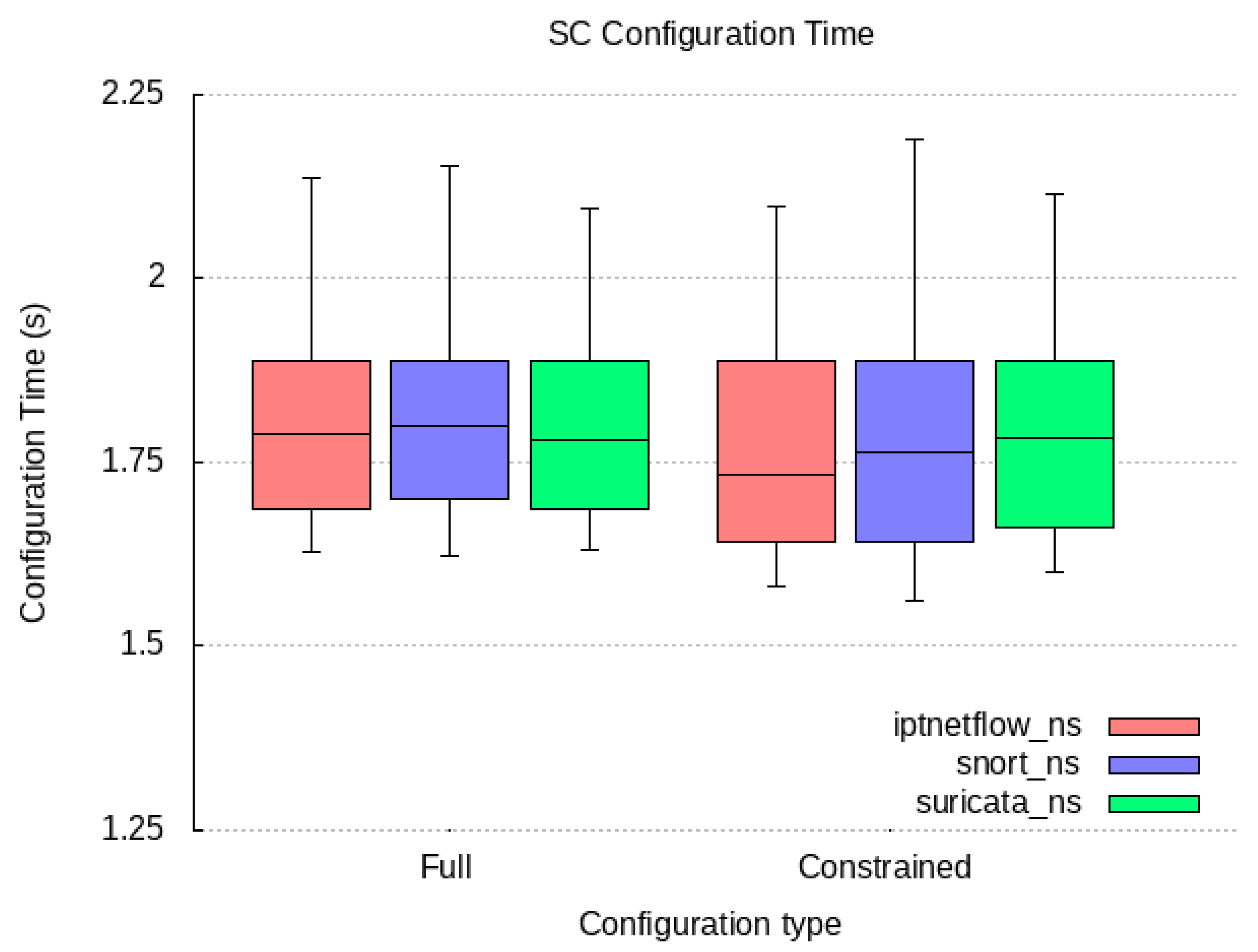
| Configuration | Full | iptnetflow_ns | 1.816 | 1.788 |
| snort_ns | 1.815 | 1.8 | ||
| suricata_ns | 1.802 | 1.781 | ||
| (Aggregated) | 1.811 | 1.788 | ||
| Constrained | iptnetflow_ns | 1.793 | 1.739 | |
| snort_ns | 1.804 | 1.764 | ||
| suricata_ns | 1.787 | 1.783 | ||
| (Aggregated) | 1.795 | 1.764 |
Disclaimer/Publisher’s Note: The statements, opinions and data contained in all publications are solely those of the individual author(s) and contributor(s) and not of MDPI and/or the editor(s). MDPI and/or the editor(s) disclaim responsibility for any injury to people or property resulting from any ideas, methods, instructions or products referred to in the content. |
© 2023 by the authors. Licensee MDPI, Basel, Switzerland. This article is an open access article distributed under the terms and conditions of the Creative Commons Attribution (CC BY) license (https://creativecommons.org/licenses/by/4.0/).
Share and Cite
Compastié, M.; López Martínez, A.; Fernández, C.; Gil Pérez, M.; Tsarsitalidis, S.; Xylouris, G.; Mlakar, I.; Kourtis, M.A.; Šafran, V. PALANTIR: An NFV-Based Security-as-a-Service Approach for Automating Threat Mitigation. Sensors 2023, 23, 1658. https://doi.org/10.3390/s23031658
Compastié M, López Martínez A, Fernández C, Gil Pérez M, Tsarsitalidis S, Xylouris G, Mlakar I, Kourtis MA, Šafran V. PALANTIR: An NFV-Based Security-as-a-Service Approach for Automating Threat Mitigation. Sensors. 2023; 23(3):1658. https://doi.org/10.3390/s23031658
Chicago/Turabian StyleCompastié, Maxime, Antonio López Martínez, Carolina Fernández, Manuel Gil Pérez, Stylianos Tsarsitalidis, George Xylouris, Izidor Mlakar, Michail Alexandros Kourtis, and Valentino Šafran. 2023. "PALANTIR: An NFV-Based Security-as-a-Service Approach for Automating Threat Mitigation" Sensors 23, no. 3: 1658. https://doi.org/10.3390/s23031658