
Improvement of Hexacopter UAVs Attitude Parameters Employing Control and Decision Support Systems
 ,
,
Abstract
:1. Introduction
2. Related Work
2.1. Latest Developments in Hexacopter Drones Design
2.2. Sensors Equipment
2.3. Experimental Procedures
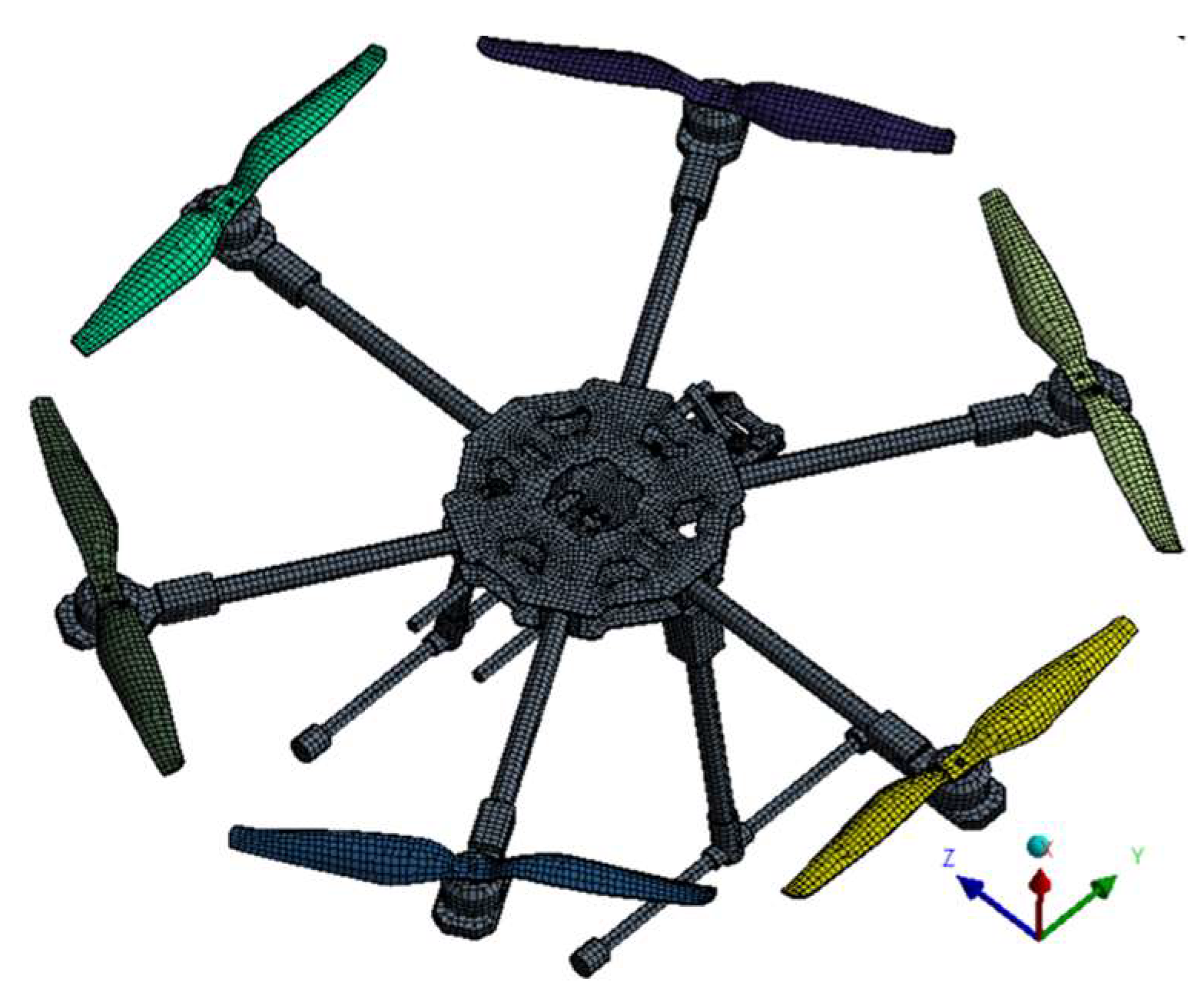
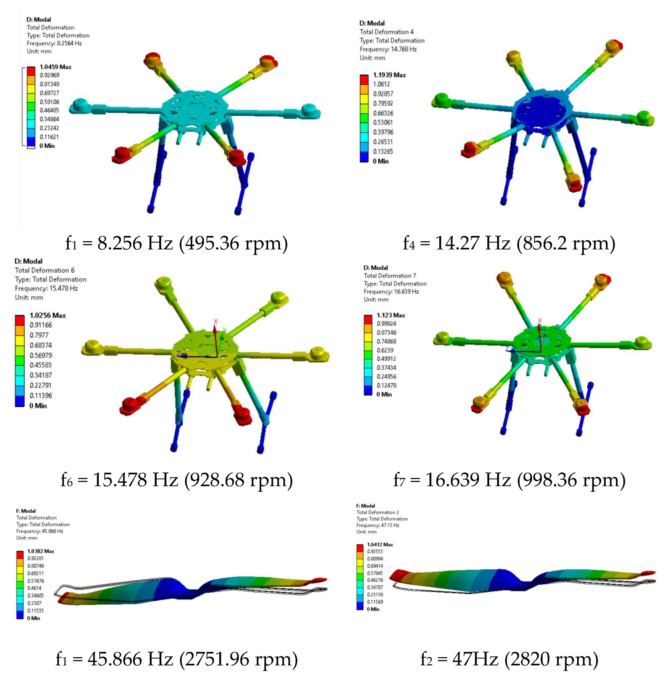
2.4. Multirotor Drones Stability Assessment Based on FEM Approach
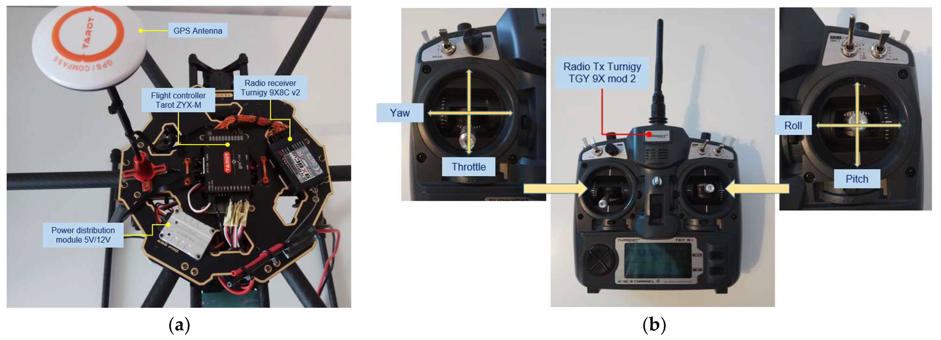
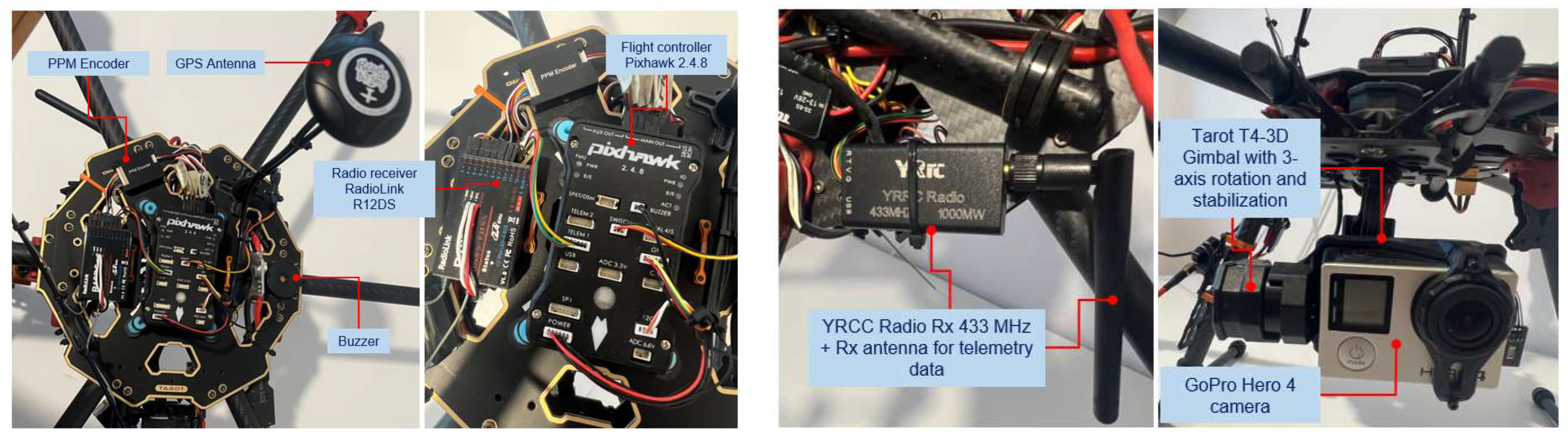
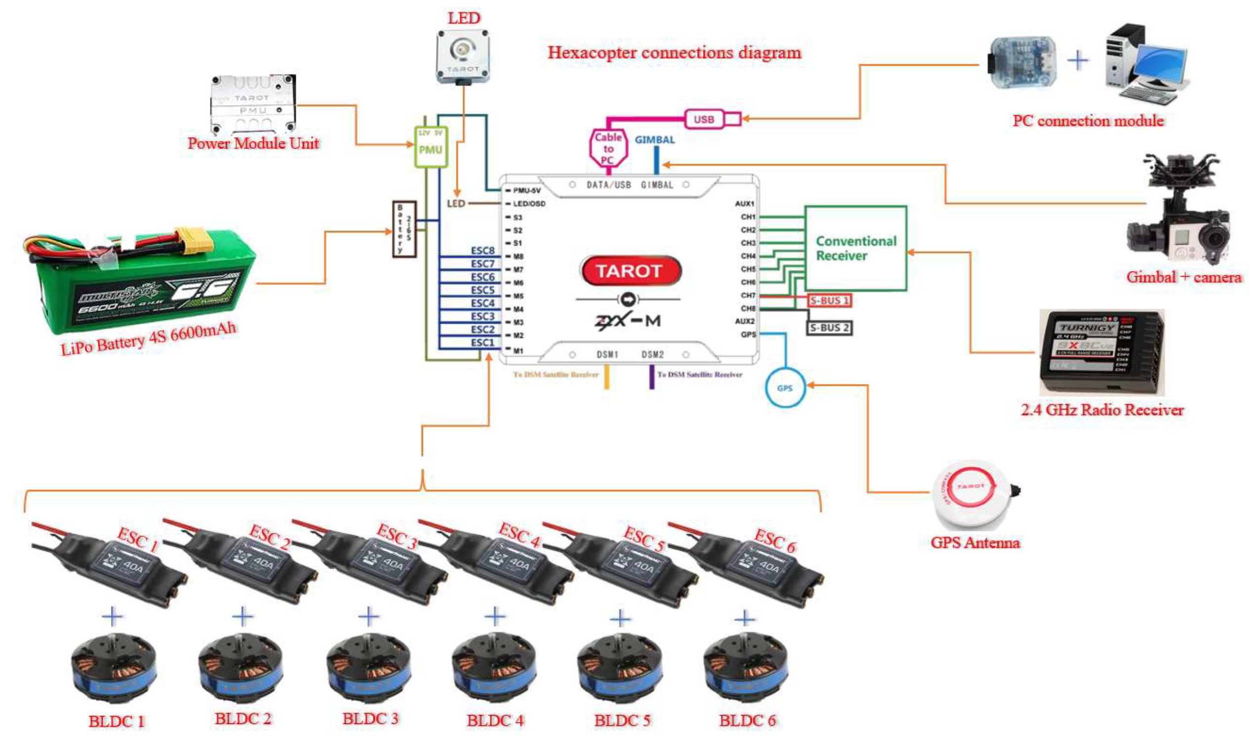
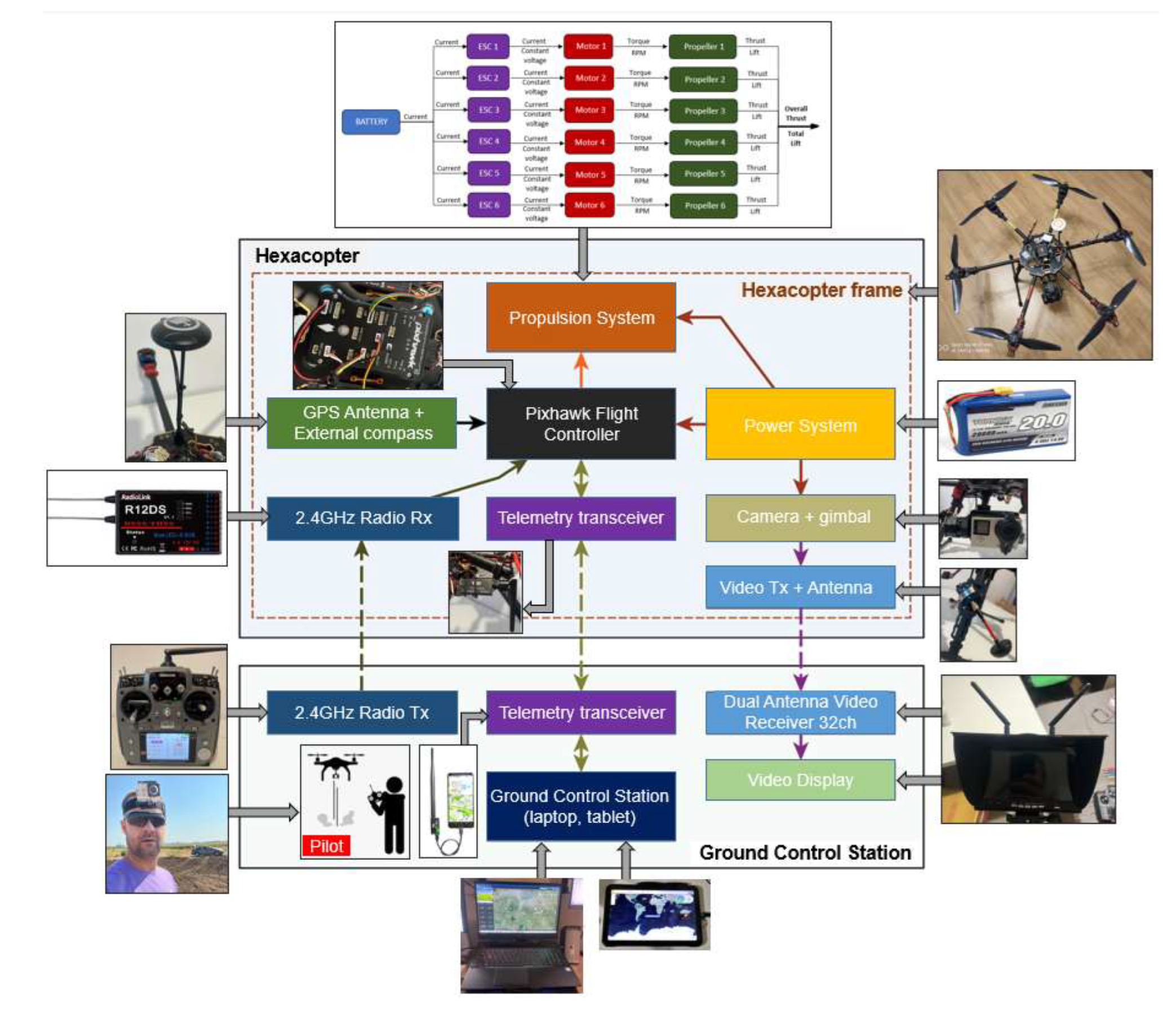
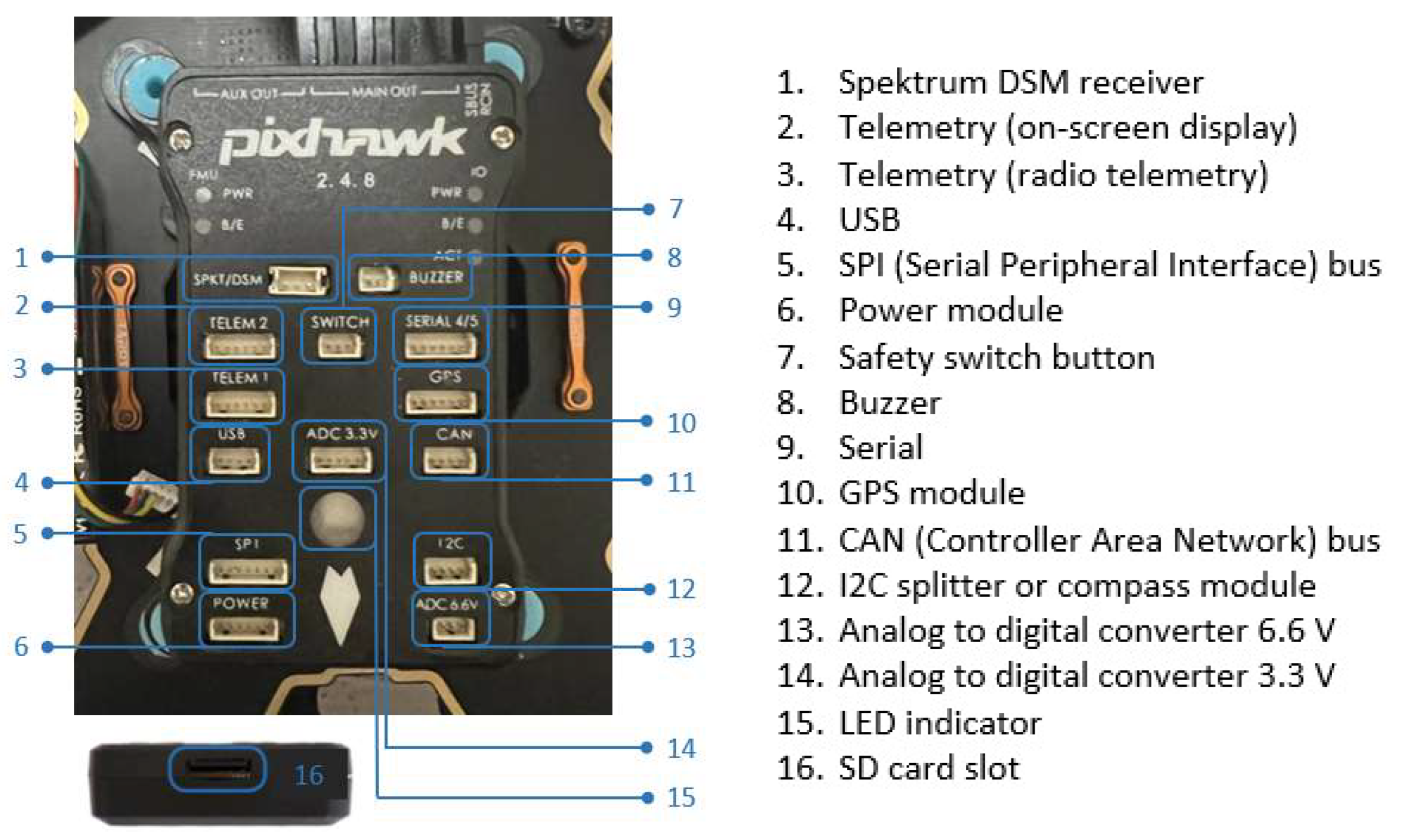
3. Hexacopter Platform Architecture
- -
- System-on-Chip STMicroelectronics STM32F427 Cortex-M4F 32-bit main microcontroller, operating frequency 180 MHz, RAM: 256 KB SRAM (L1), 2 MB Flash memory for writing instructions.
- -
- System-on-Chip STMicroelectronics STM32F100 Cortex-M3 32-bit, 24 MHz operating frequency, 8 KB SRAM (L1), 64 KB Flash memory for writing instructions.
- -
- Embedded sensors on the motherboard: ● a 3-axis STMicroelectronics L3GD20H 16-bit gyroscope sensor; ● a 14-bit STMicroelectronics LSM303D accelerometer/magnetometer sensor; ● an Invensense MPU-6000 3-axis accelerometer/gyroscope sensor; ● a TE Connectivity MEAS MS5611 barometer sensor.
4. Laboratory and In Situ Measurement Results and Discussion
4.1. Laboratory Tests
- -
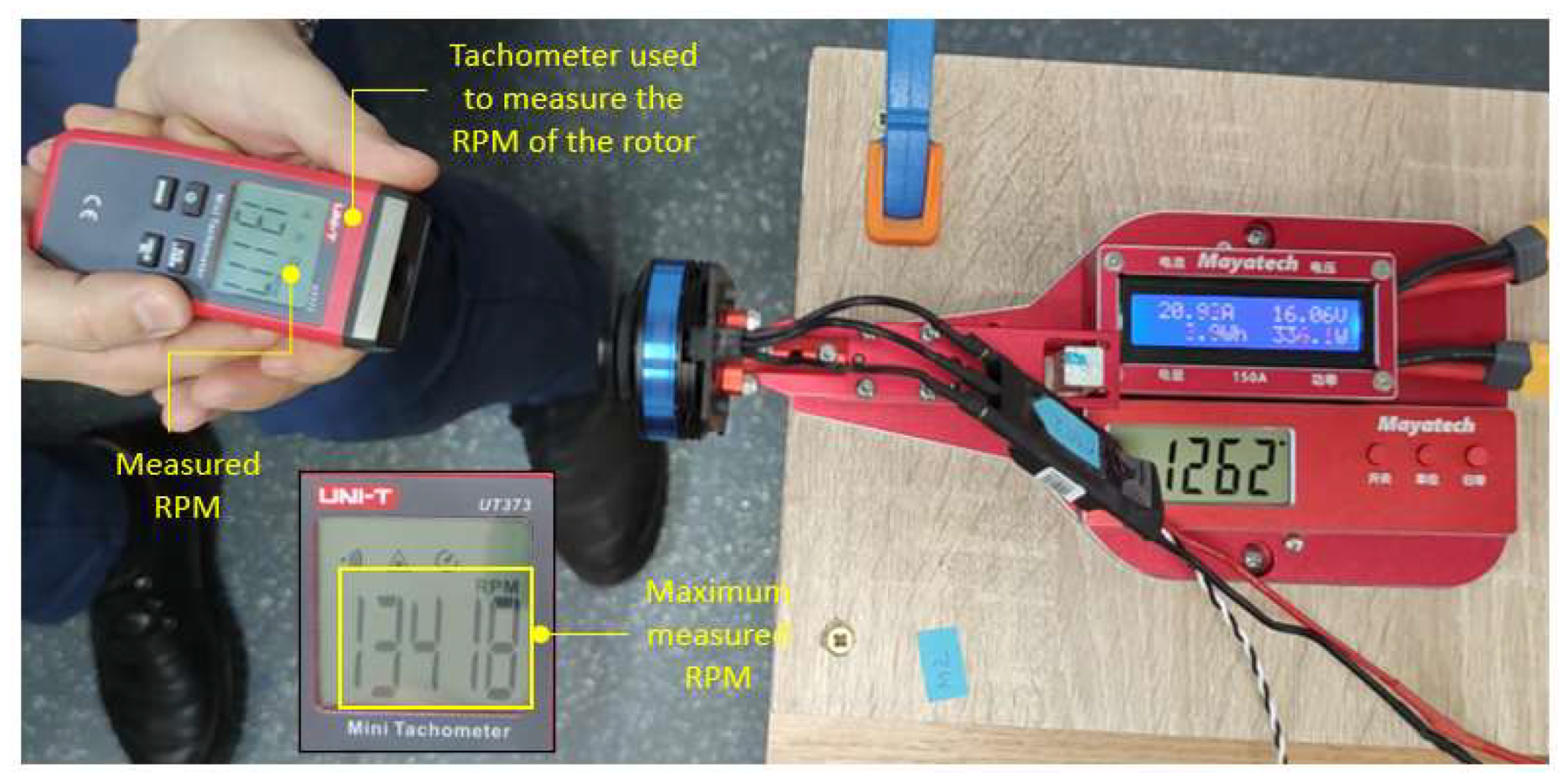
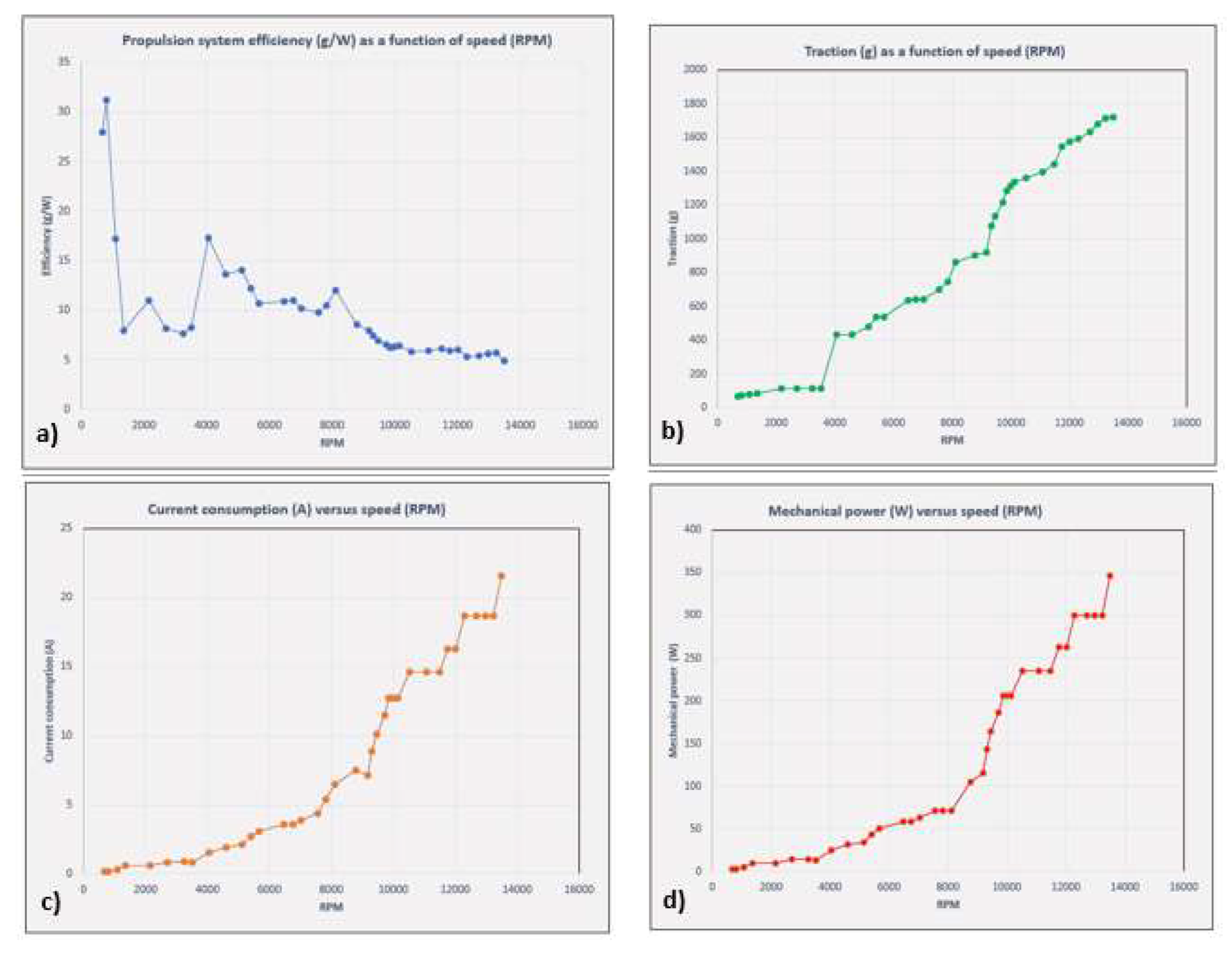
- The maximum thrust force produced by the rotor assembly, measured on the stand, was approximately 1.718 Kgf ≈ 16.84 N.
- -
- Maximum speed measured by the tachometer—13418 rpm.
- -
- The efficiency of the propulsion system decreases with increasing rpm. In the idling zone, at 30–40% rpm, the efficiency reaches a value of 13–14 g/W (≥6 g/W—high-efficiency drone). In the 50–75% rpm range, which is equivalent to operating the drone in hover and light horizontal manoeuvres, the efficiency decreases to a value of 6.49 g/W (≥6 g/W—high-efficiency drone). In the speed range of 85–100%, the efficiency further decreases to a minimum value of 4.96 g/W (4 ÷ 6 g/W—low-efficiency drone).
- -
- With increasing speed, the current consumption increases proportionally, reaching a measured current value at 100% speed of 21.6 Ah.
- -
- The mechanical power produced also increases to a value of 346.2 W at 100% speed.
- -
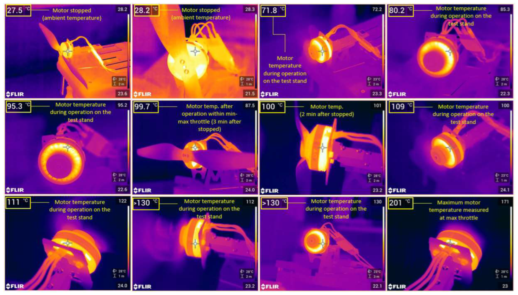
- At idle, with the throttle stick at 30%, for a 3–5-min interval, the motor temperature reached 40 °C.
- -
- At idle, with the throttle stick at 50% for 3–5 min, the motor temperature reached 60 °C.
- -
- In maximum mode, with the throttle stick at 100%, for 3–5 min, the temperature reached over 200 °C, which means that it is only desirable to operate the drone in maximum mode for very short periods, around 10–15 s, to avoid these temperature increases in the motor windings, which can eventually lead to burn-out and thus their permanent damage.
4.2. Online Testing Platforms Results
- -
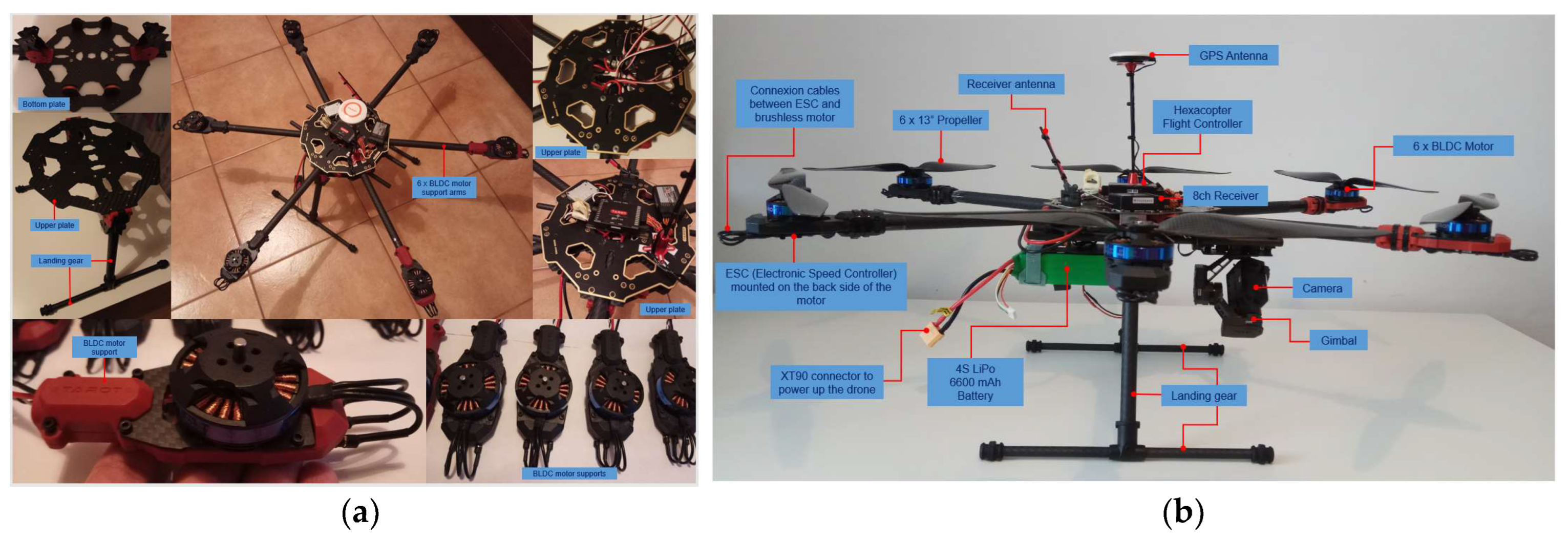
- Frame size is 695 mm and is made of carbon fibre epoxy resin with a total mass of only 833 g, while providing increased shock and vibration resistance.
- -
- The propellers were 13’’ with 5.5″ pitch—the size of the drone frame limits the mounting of propellers with a maximum diameter of 13″.
- -
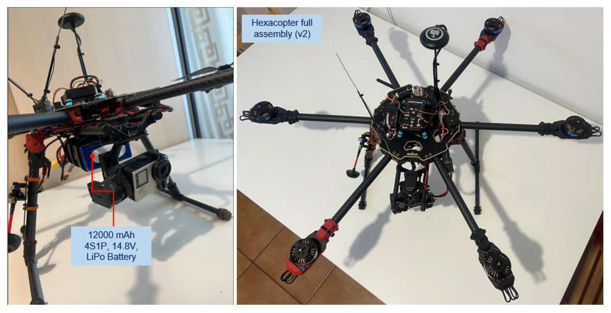
- Four-cell LiPo battery capacity—16 Ah, in 4S2P configuration with 12-24C C-rating, 14.8 V nominal voltage.
- -
- Flight testing of the HDT was simulated at an altitude of about 85 m above sea level (Bucharest altitude), at a temperature of 22 °C and at an atmospheric pressure of 1010 hPa (757.5 mmHg).
- -
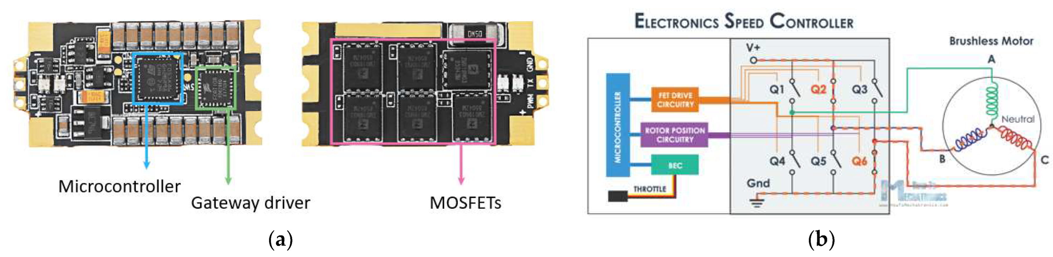
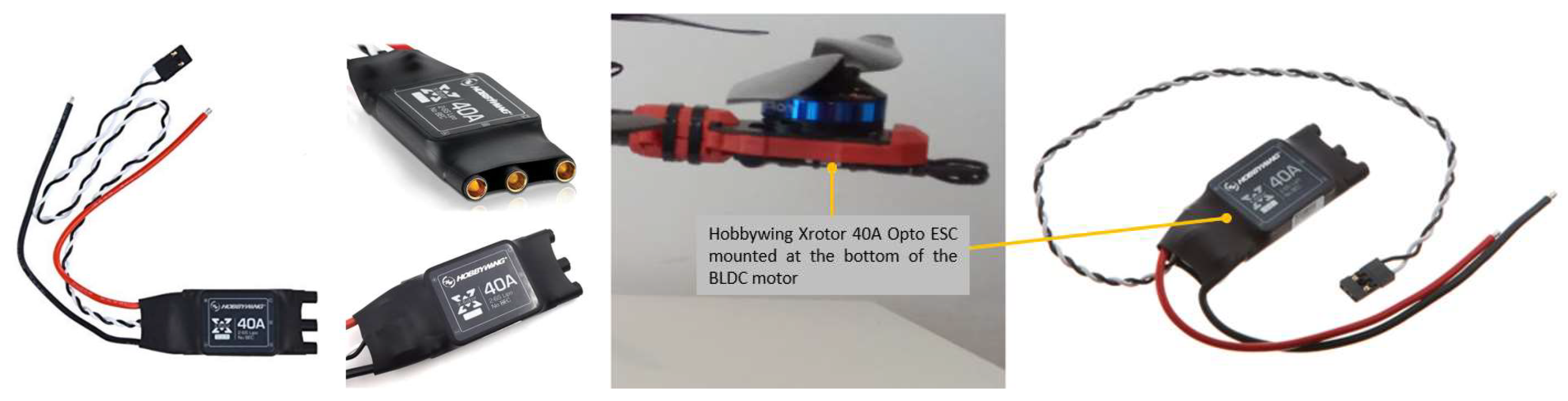
- Electronic speed controllers (ESC) can withstand a maximum current of 40A and have an internal resistance of approximately 0.0006 Ohm and a mass of 26 g each.
- -
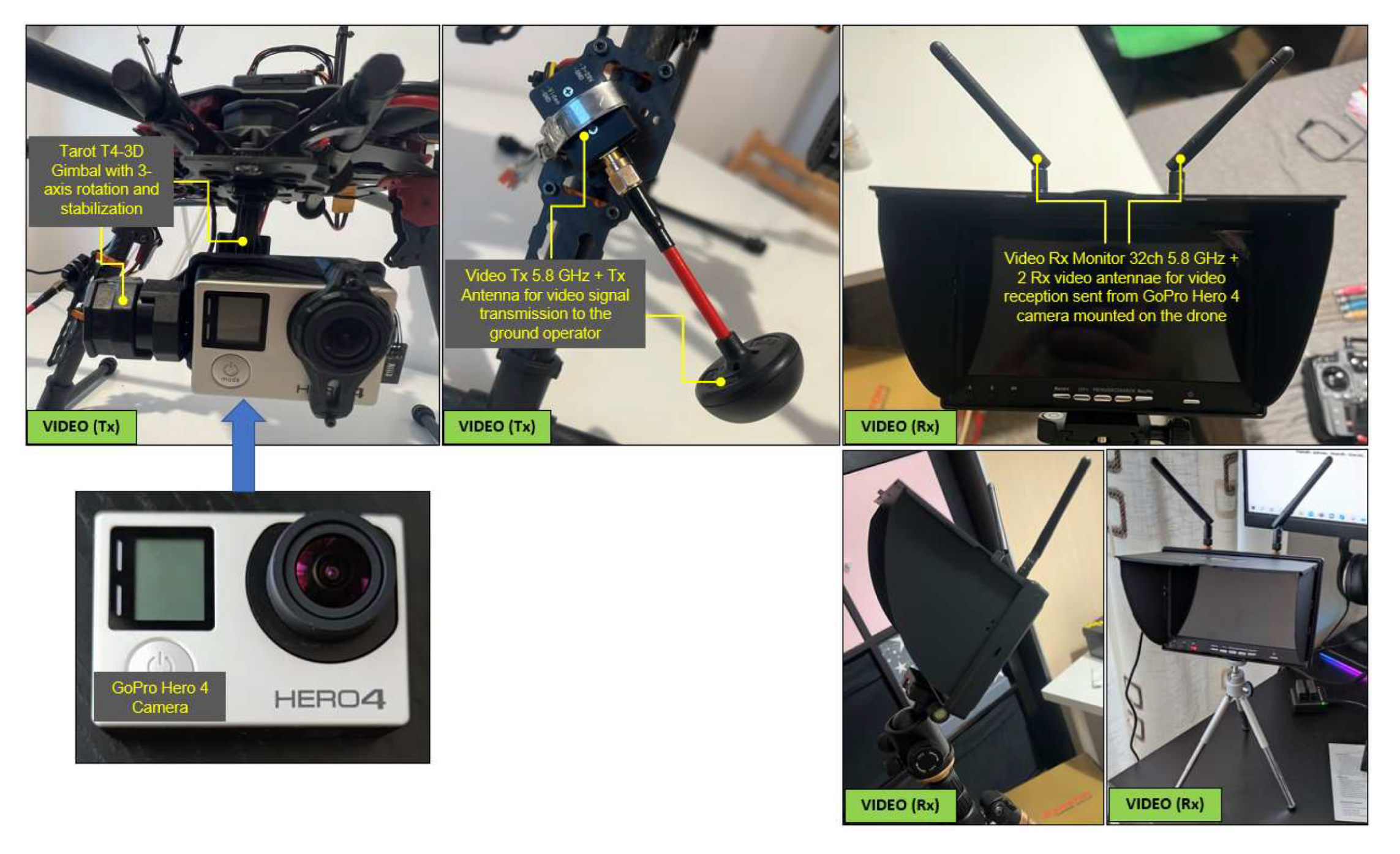
- The hexacopter has a three-axis rotating and stabilizing gimbal; it has a mass of 178 g and consumes approximately 0.05 A.
- -
- Tarot 4006/620KV BLDC motors produce 620 rpm/V and have an internal resistance of 0.126 Ohm and a mass of 82 g each.
- -
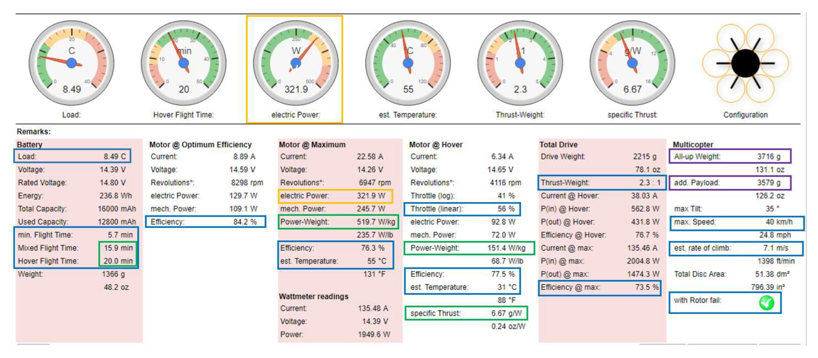
- Load on the battery (load) is 8.49C (which means a continuous load below 12C A of the battery, i.e., 8.49 × 16A ≈ 136A < 12 × 16 ≈ 192A).
- -
- A considerable increase in flight time to 15.1 min for combined flight and 20 min for hover flight, compared to lower capacity batteries used in previous tests.
- -
- For optimum motor performance, a slight increase in efficiency from 84.1% to 84.2% is obtained; for fixed-point flight, a speed of 4116 rpm is obtained. The motor speed increases from 48% to 56% of capacity (which is a good result), a power-to-mass ratio of 151.4 W/kg, an efficiency of 77.5% and a temperature of only 31 °C. However, as an element to be taken into account, an increase in power (at engine input) to 321.9 W (but only at maximum engine speed) is noted.
- -
- The thrust-to-mass ratio in this case is 2.3:1 (>1.8—very good value).
- -
- The specific thrust of the propellers is 6.67 g/W, so high efficiency.
- -
- Additional equipment with a mass of about 3.6 kg can be attached.
- -
- The maximum speed is 40 km/h, and the ascent rate of 7.1 m/s;
- -
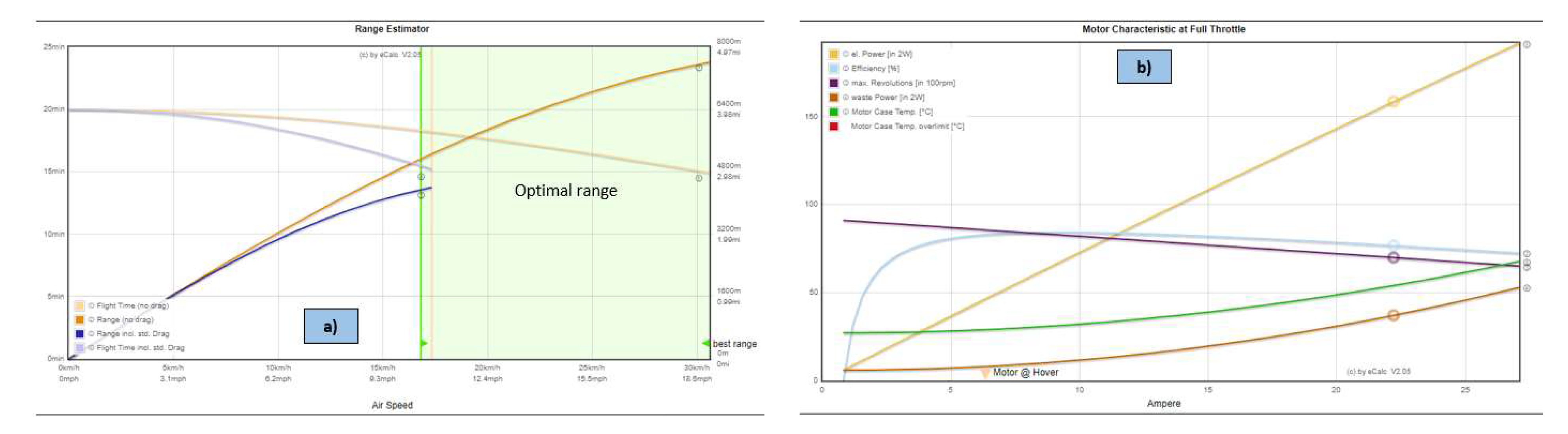
- The maximum flight time (without drag) is about 20 min;
- -
- Maximum flight time (with drag) decreases to 15.1 min;
- -
- The maximum flight distance (without drag) is approximately 7600 m;
- -
- The maximum flight distance (with drag) is approximately 4400 m;
- -
- The best performance for the hexacopter is achieved within the speed range 17 ÷ 31 km/h;
- -
- From Figure 16, it can be observed that the engines succeeded to operate in all speed ranges at an acceptable temperature of maximum 55 °C, which is very good for flight stability and proper functioning of the avionics and airborne sensors.
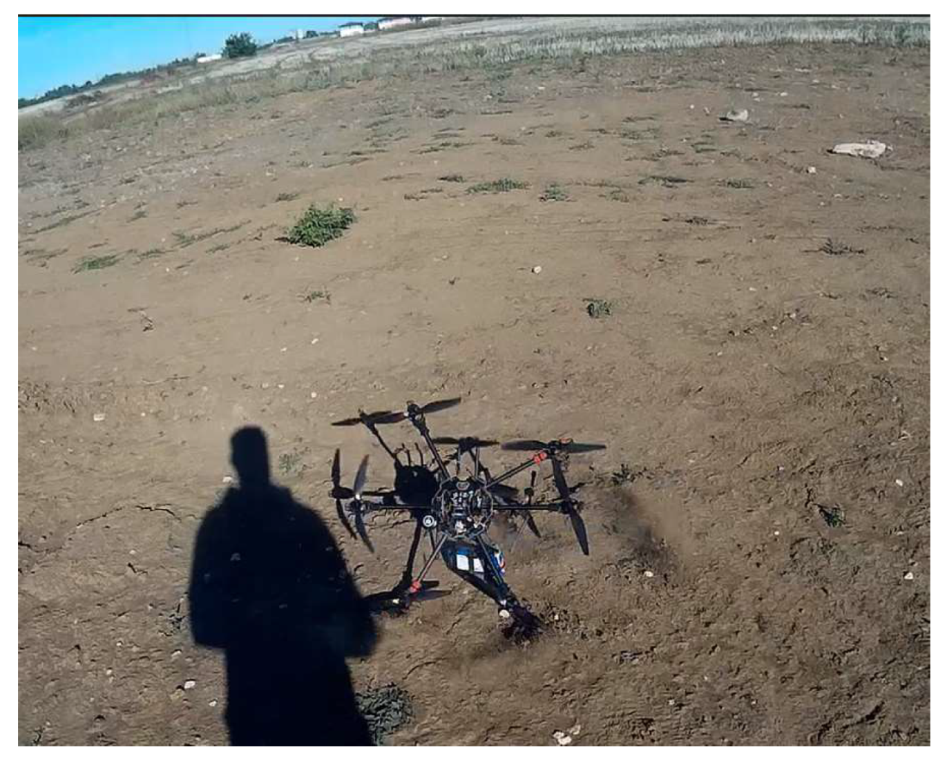
4.3. In situ Ground and In-Flight Experiments
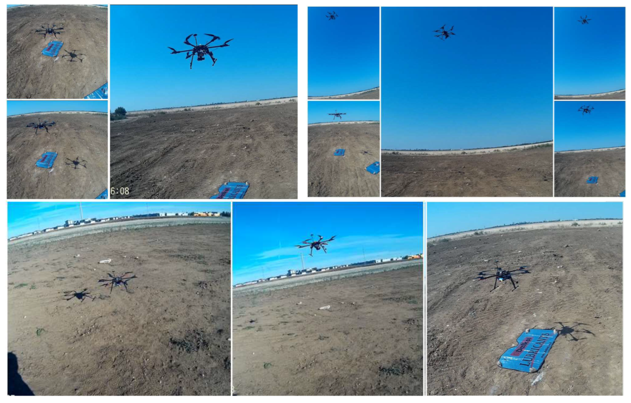
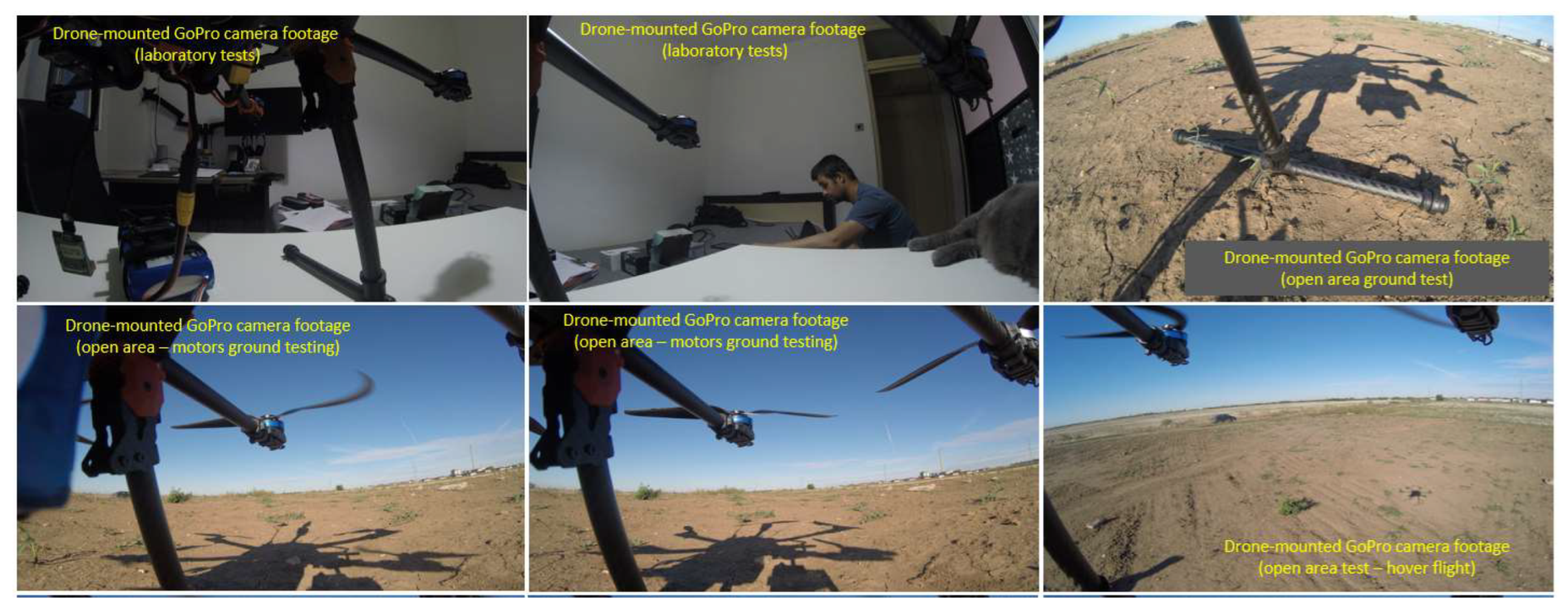
4.3.1. Hover Flight
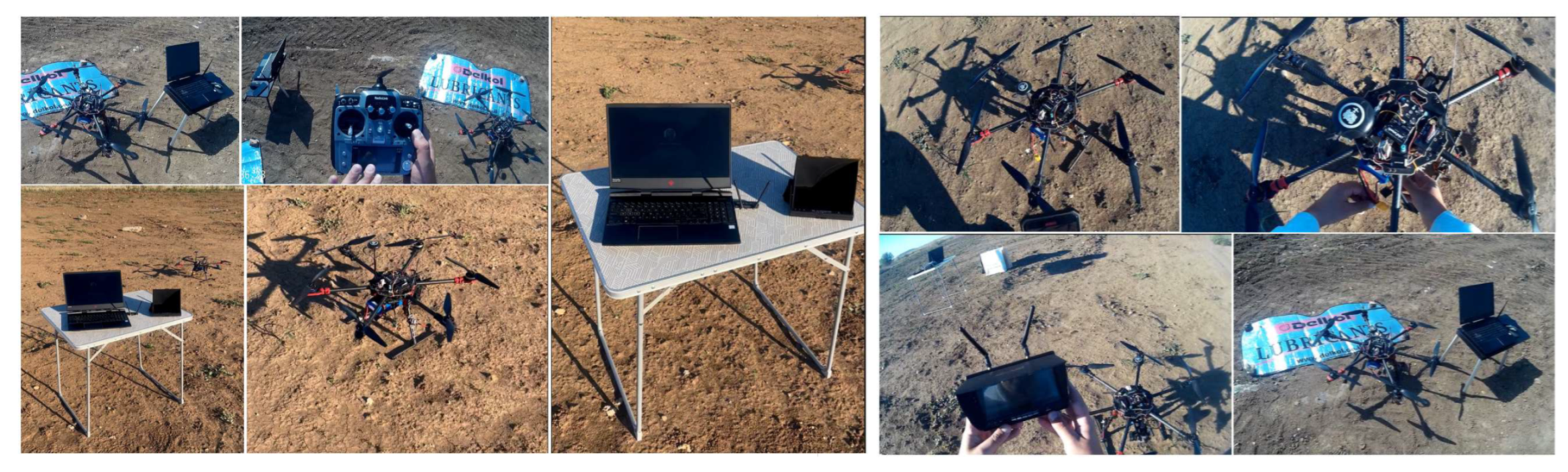
Ground Test
- -
- Inspection of the structural integrity of the drone. Each joint of the structural elements is checked and must be well secured to ensure its rigidity.
- -
- Checks of the weight and the drone equilibrium. These checks provide information on the location of the actual centre of gravity in respect to all three axes X, Y and Z. The centre of gravity location affects the performance and stability of the drone in flight.
- -
- Examination of the avionic systems operation: controller, navigation, power supply, video system, telemetry data transmission system and wiring. All data concerning the operating limits of the equipment must be memorized in order to avoid undesirable events such as maximum drone range, maximum operating range of the radio controls, battery capacity, power consumption of the various electronic components, maximum authorized flight altitude and legislative aspects concerning the operation of the drone in certain areas, depending on the geographical layout. In the case of autonomous flight following a preprogrammed route, the flight controller has programmed the flight scenario, the flight parameters and the failsafe measures required in the event of emergencies such as the loss of radio link between the drone and the operator, battery voltage falling close to the critical value and a motor shutdown.
- -
- Test of the motor’s operation by simple on/off commands to ensure the rated static performance based on throttle stick position, increasing the speed incrementally up to 10–15% and checking their operation, oscillations, noises, proper propeller rotation directions.
- -
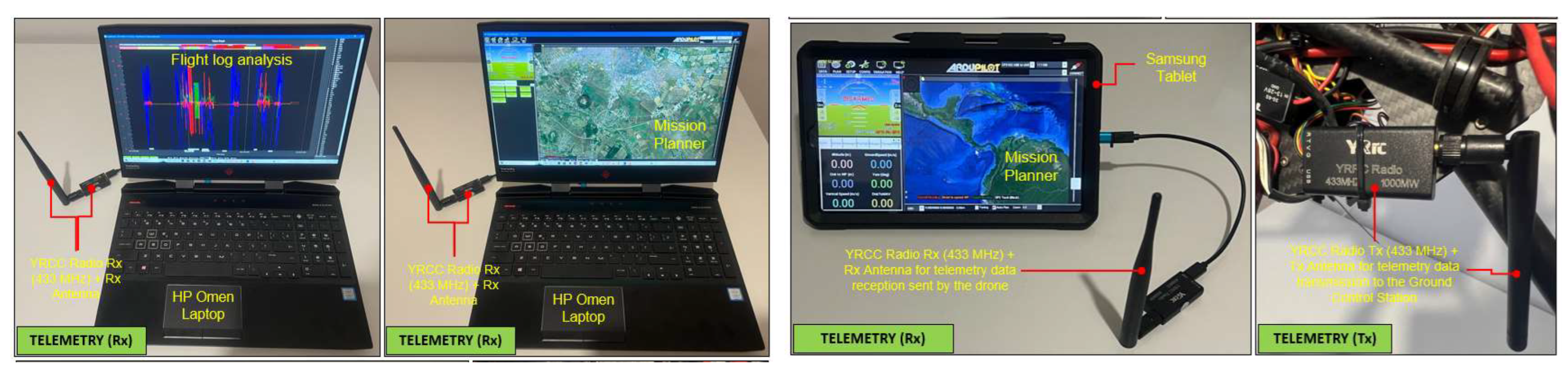
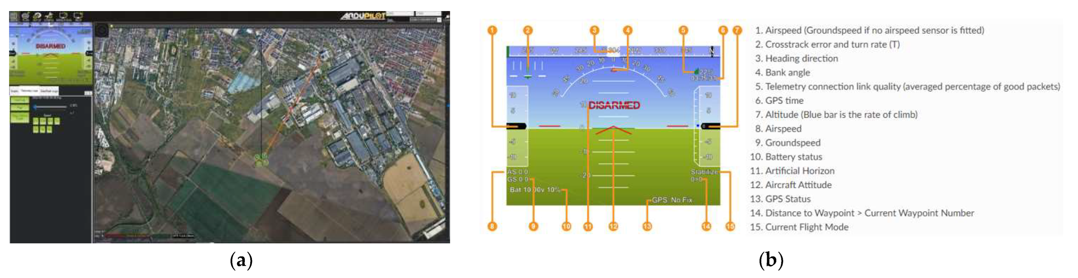
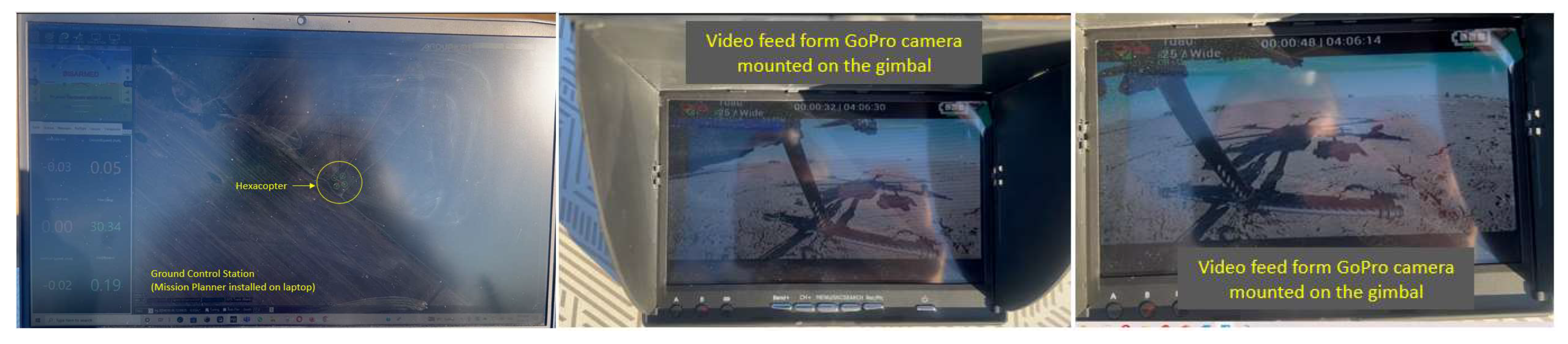
- Telemetry data link tests between the drone and the mission planner ground control station. This ensures the stability of the radio link between the drone and the operator. With the help of the control station, the operator can either plan autonomous flights on preprogrammed routes or intervene in the control of the hexacopter in emergency conditions if the radio control is not used.
- -
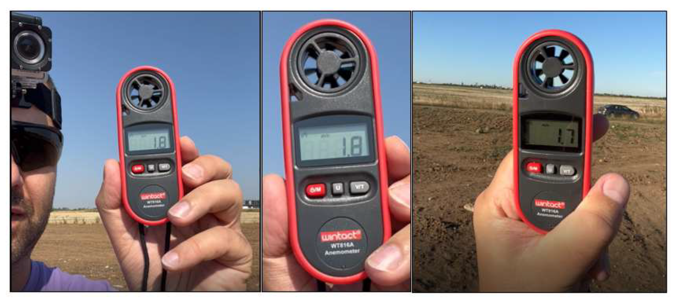
- Weather condition checks: wind speed, temperature, precipitation and atmospheric pressure. This is an extremely important step in planning a flight, as there are limitations to operating the hexacopter.
Hover Flight Tests
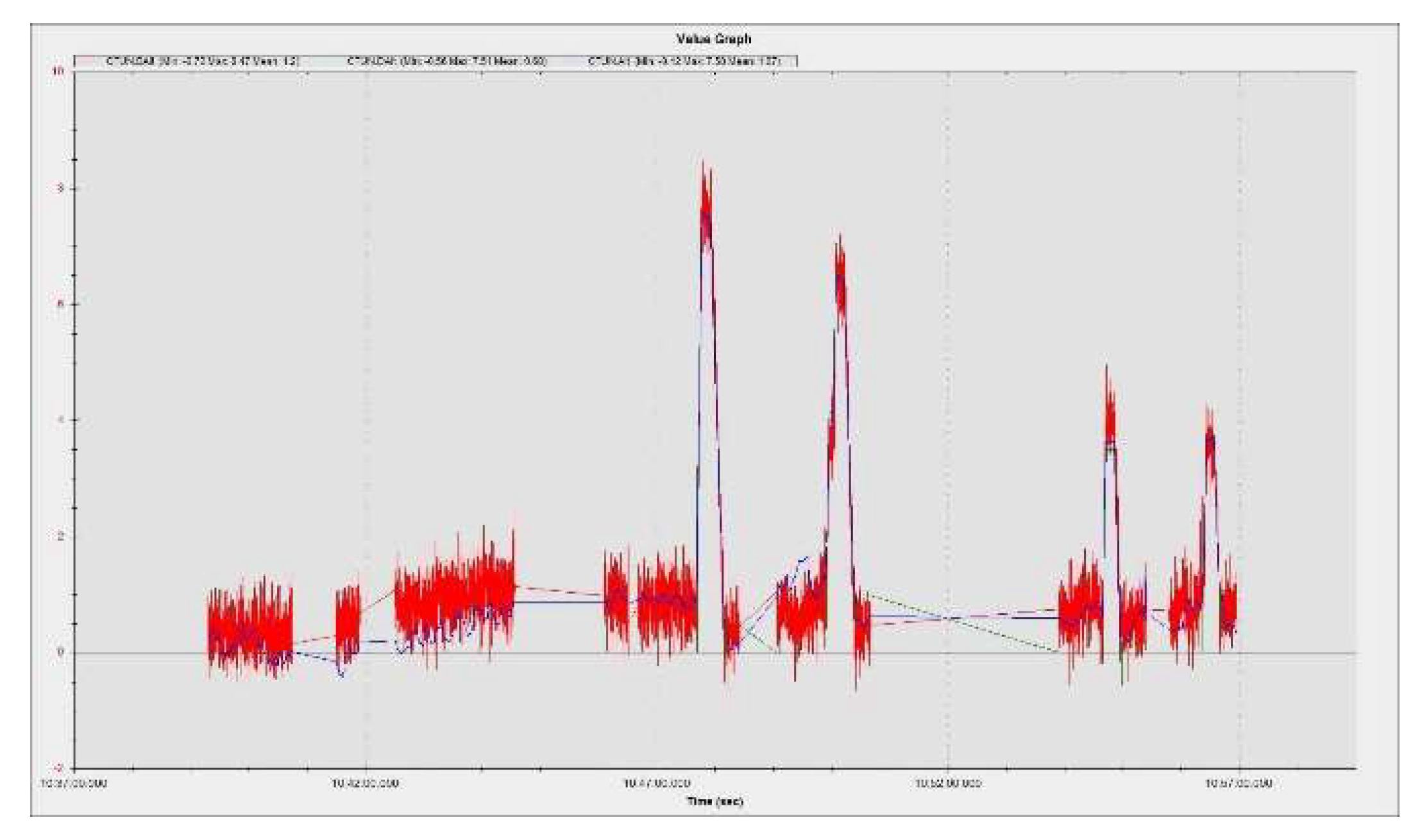
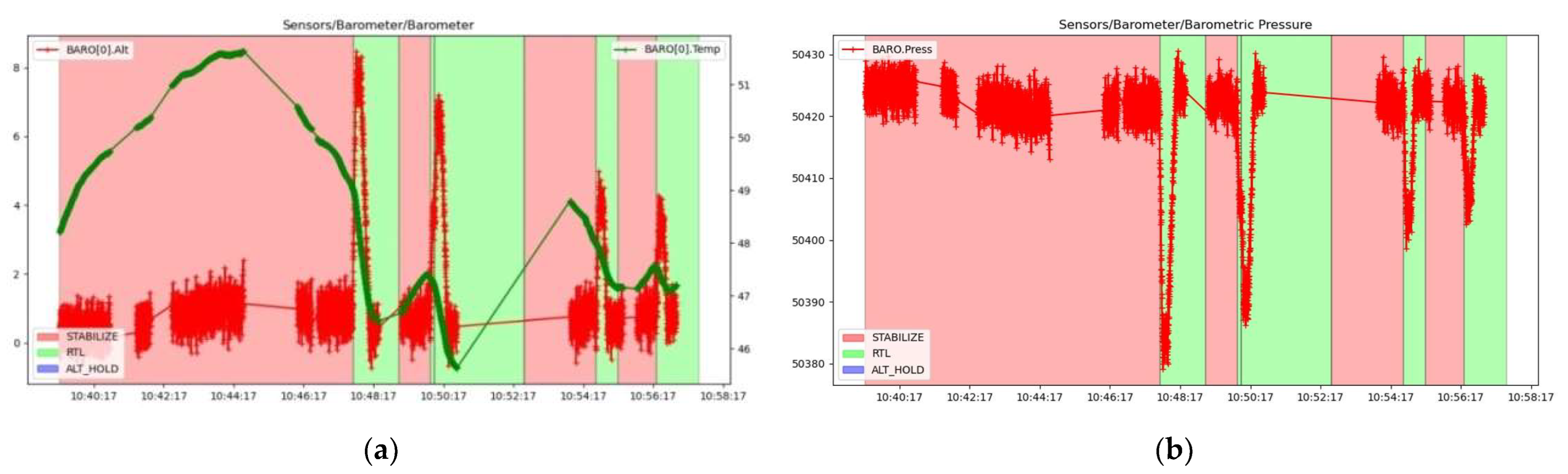
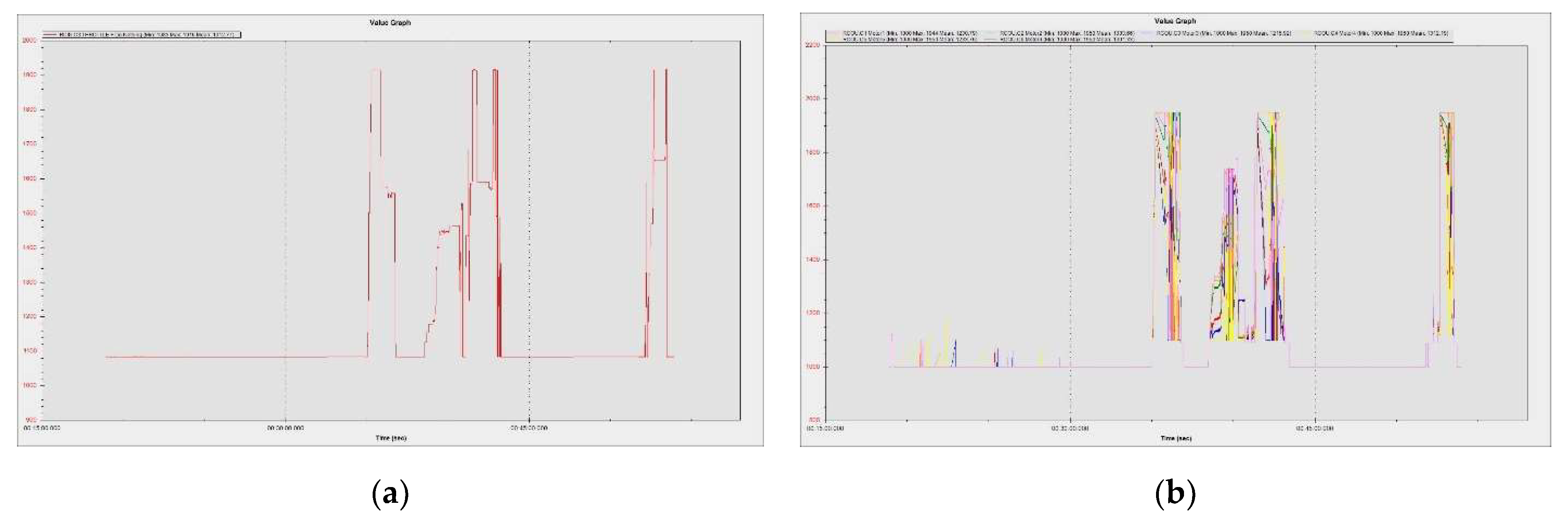
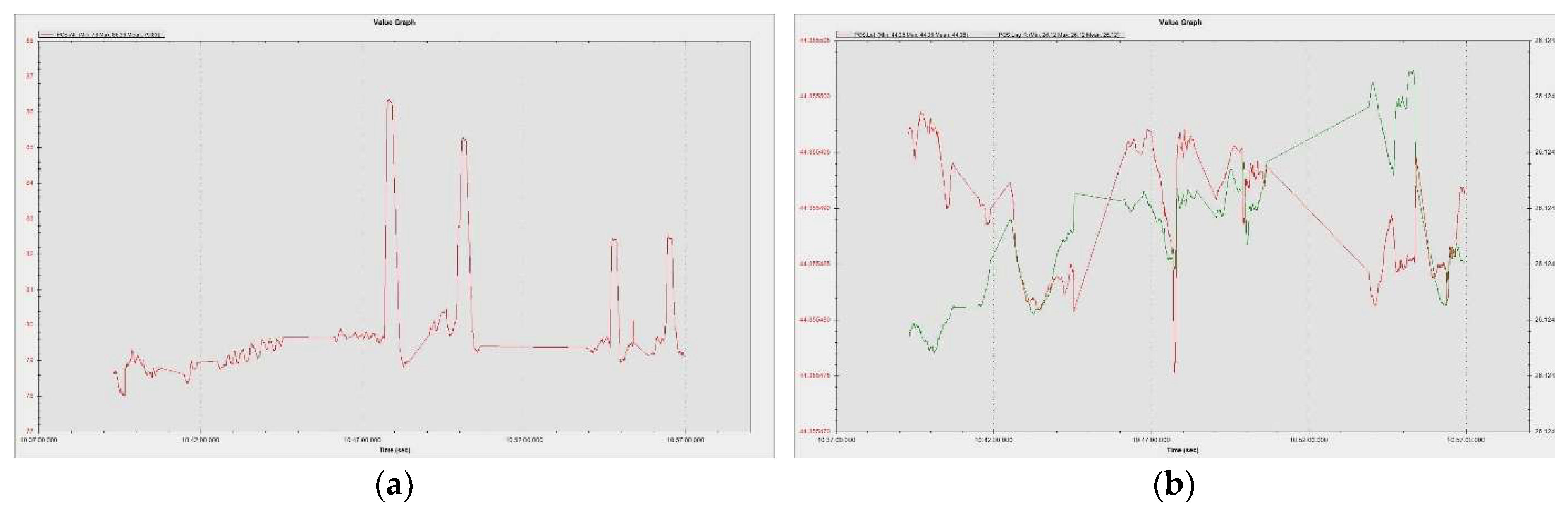
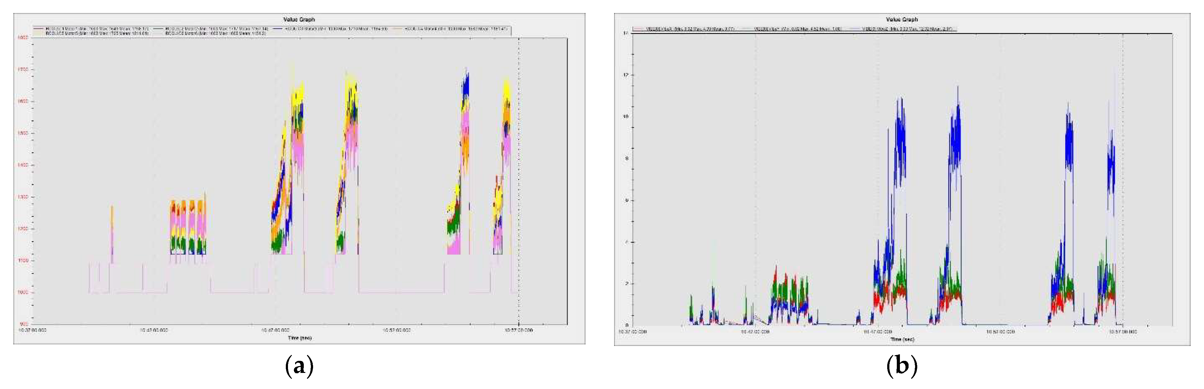
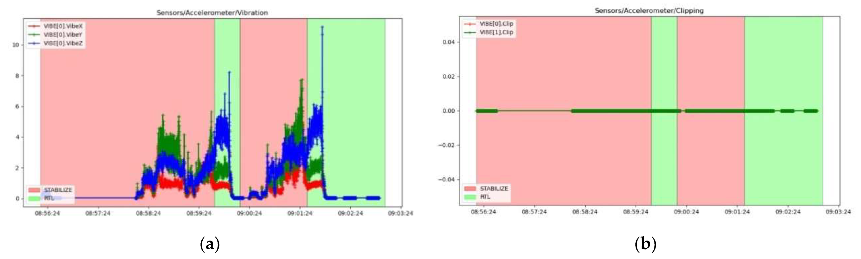
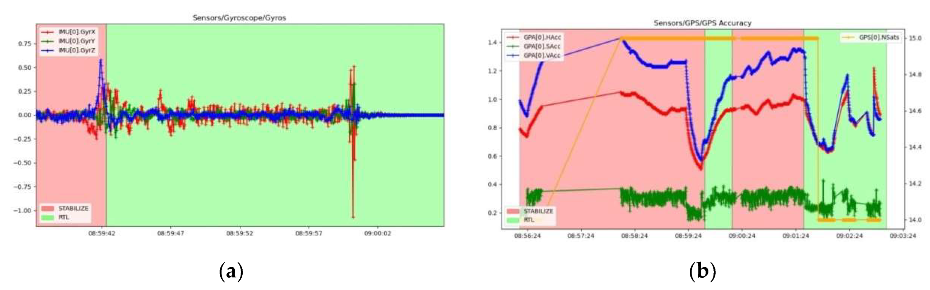
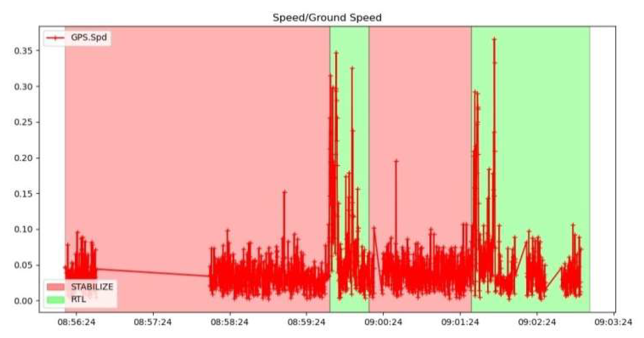
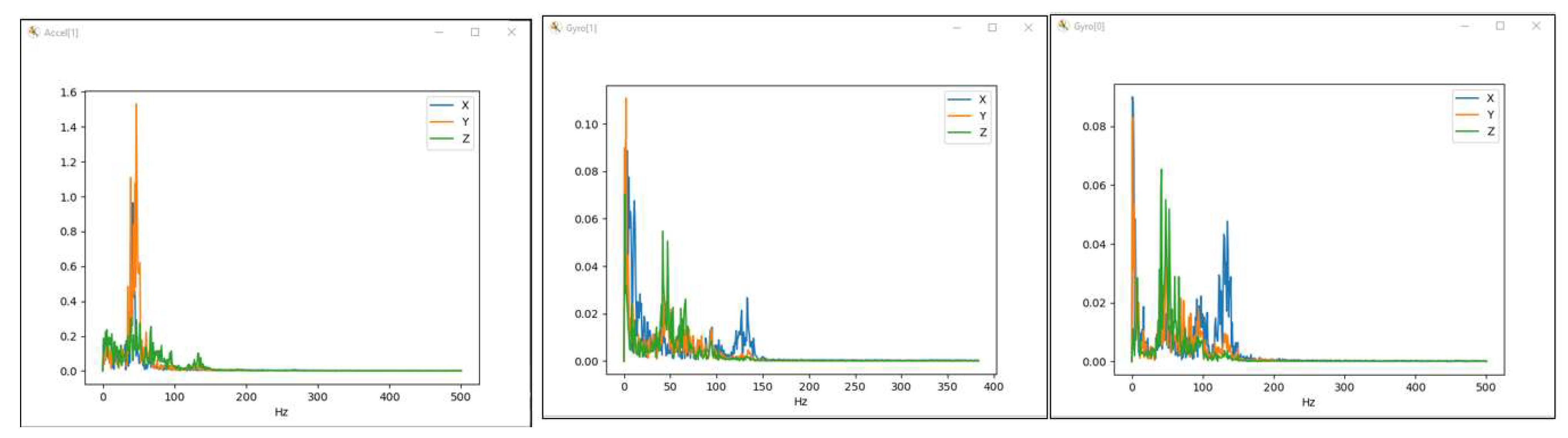
4.3.2. Hexacopter Flight Parameters Extracted from Sensors during Hover Flight
5. FEM Decision Support
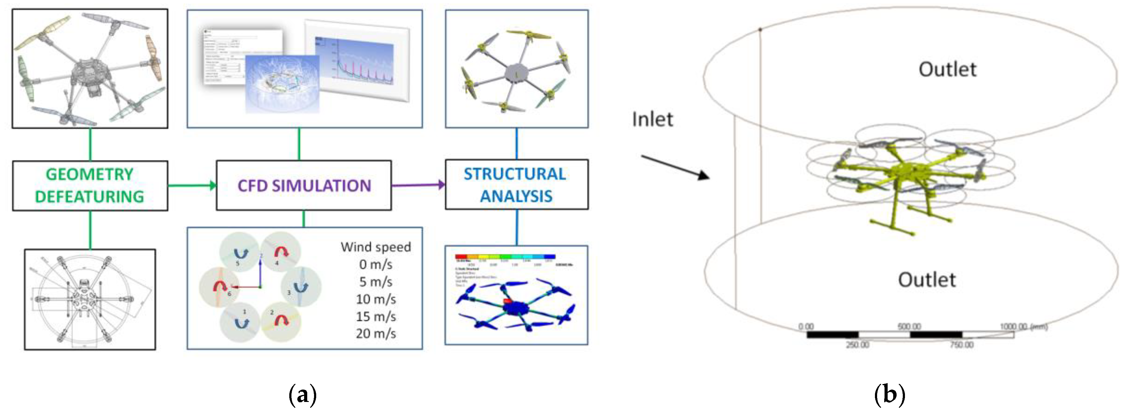
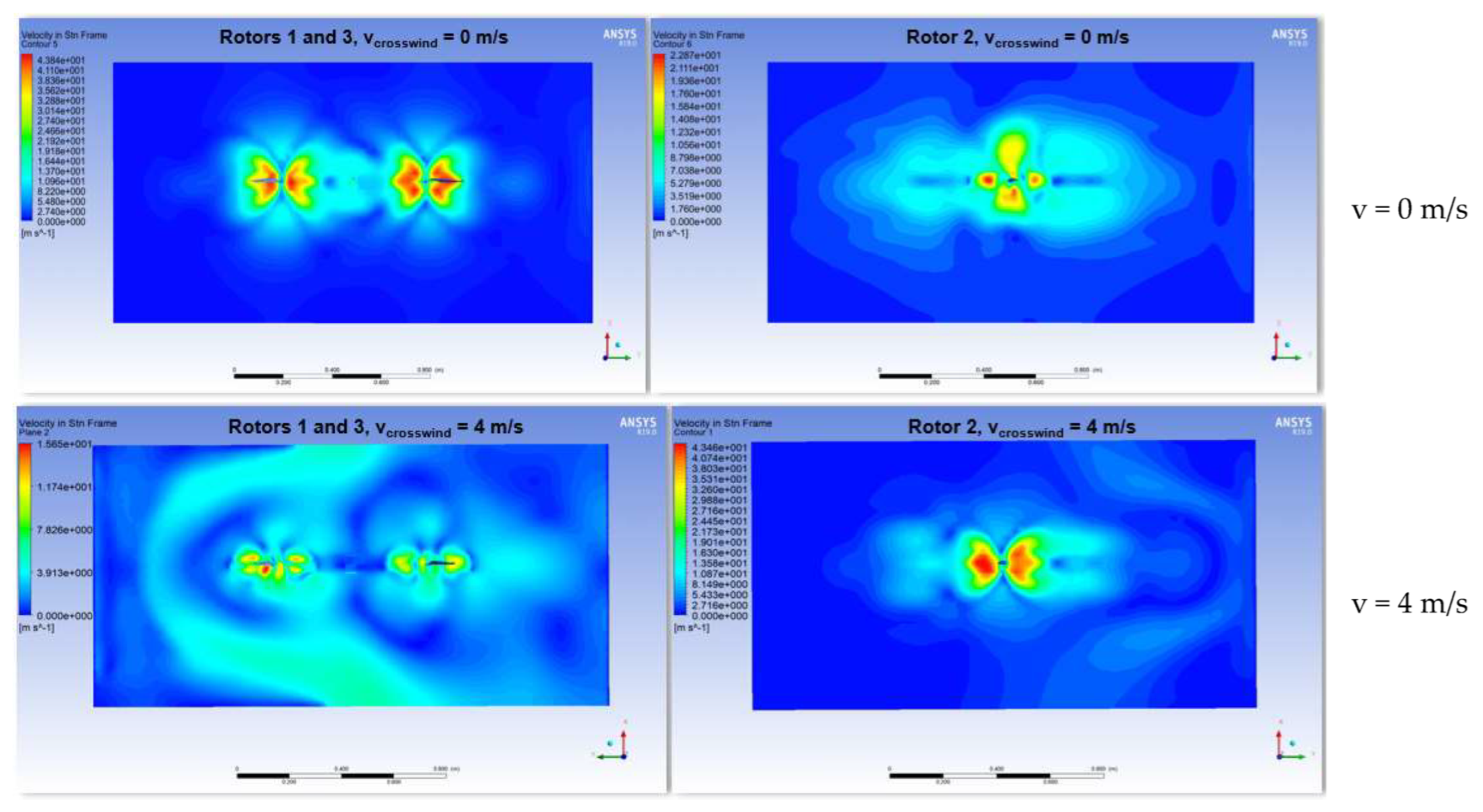
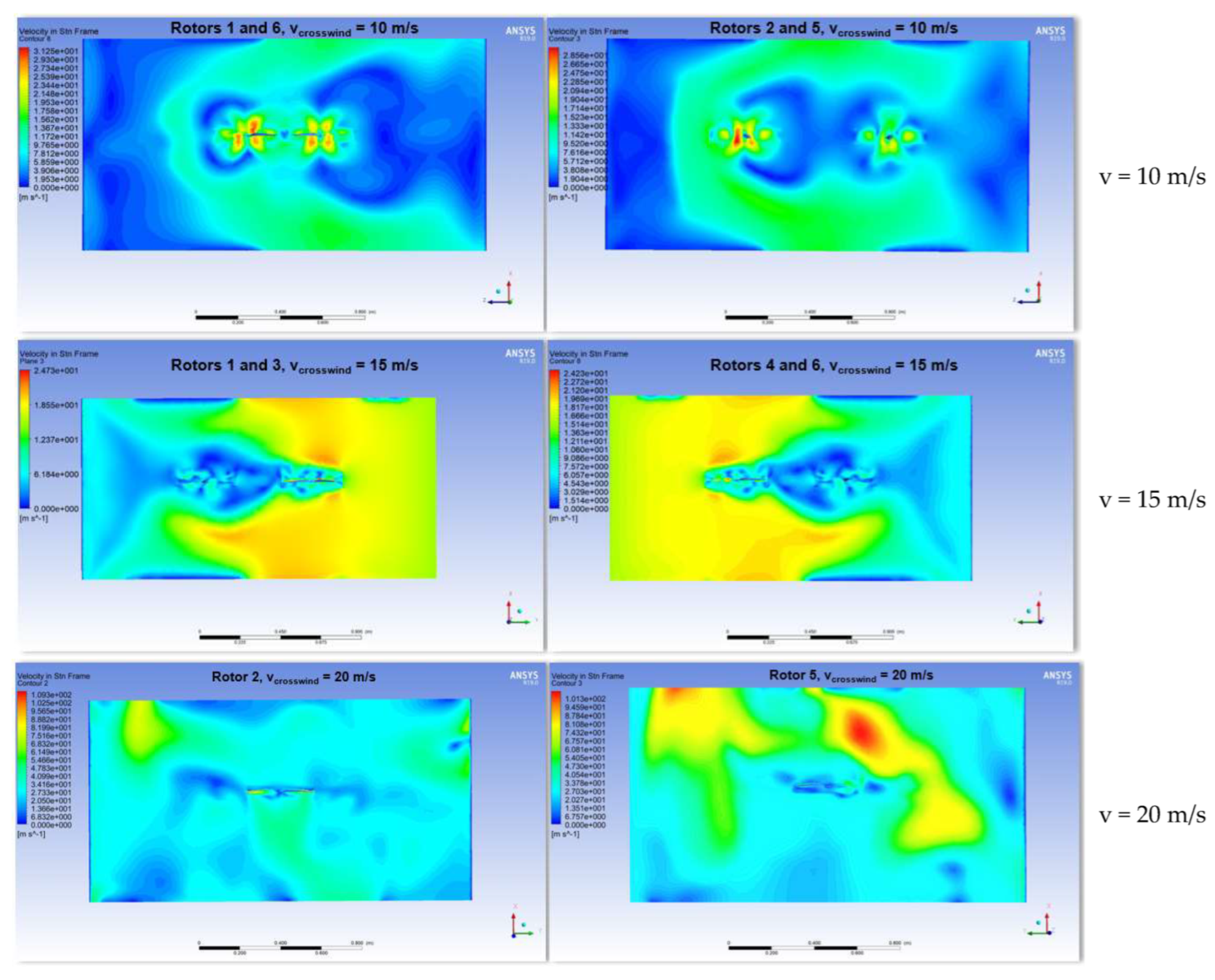
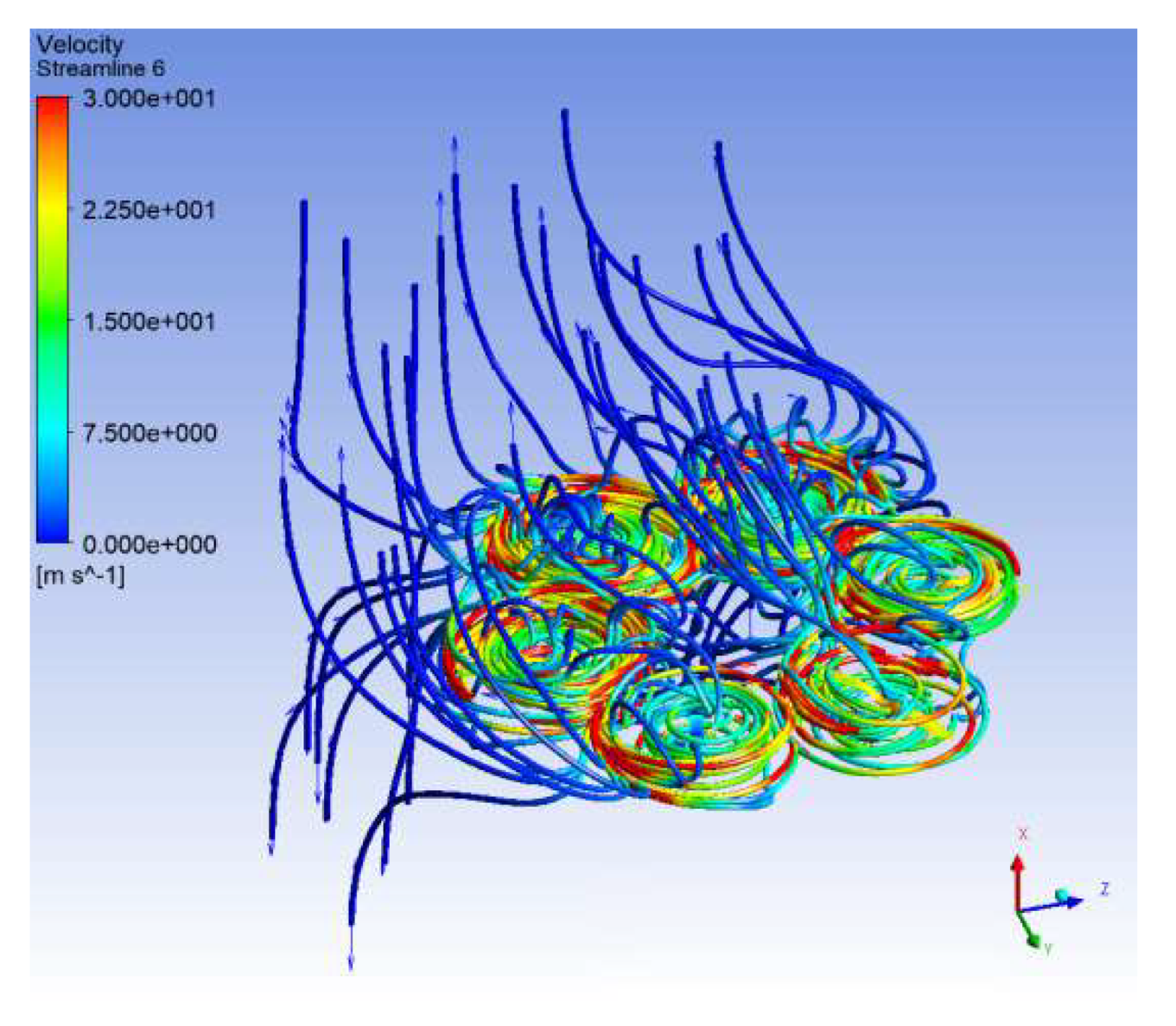
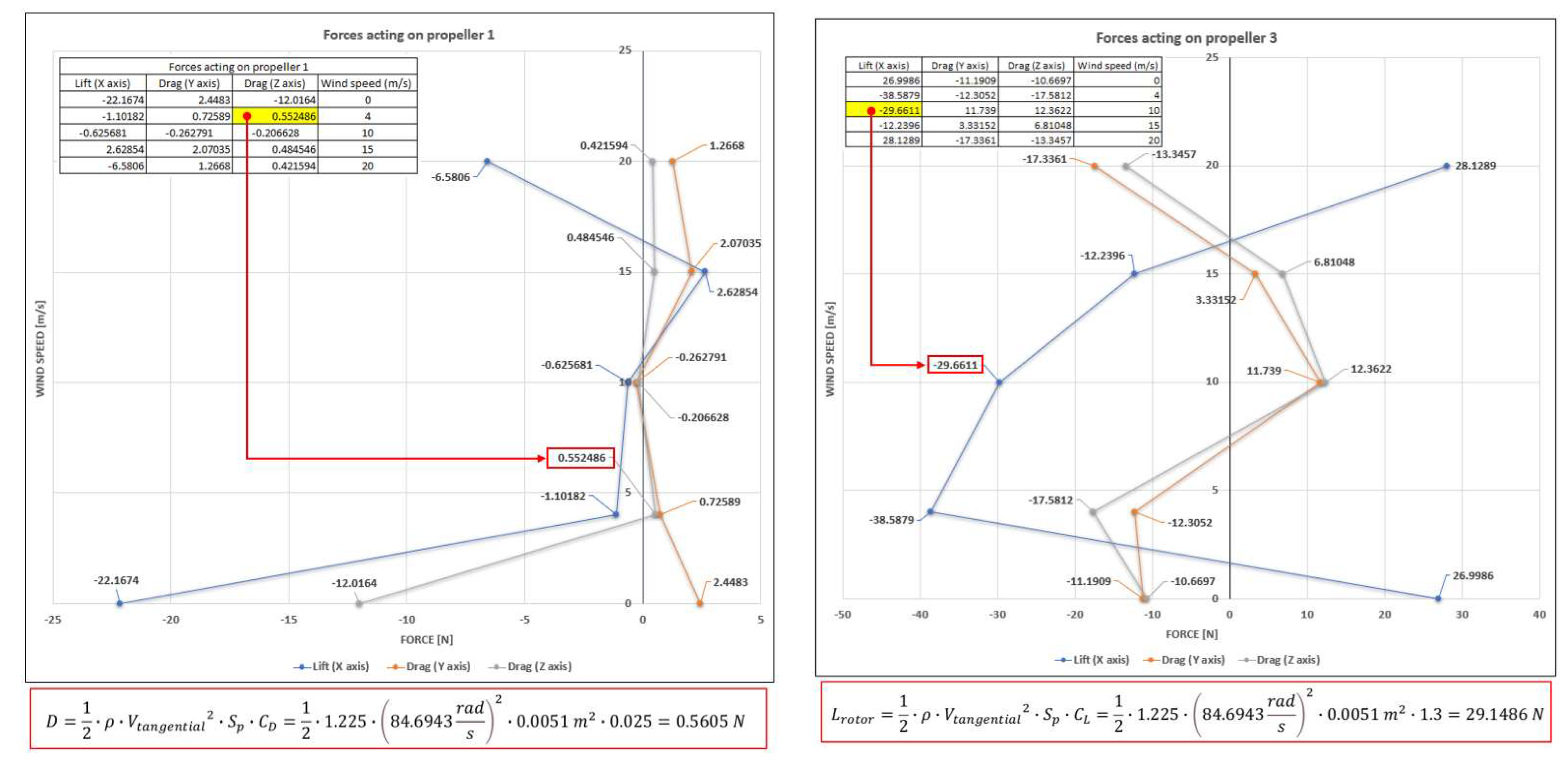
5.1. CFD Approach
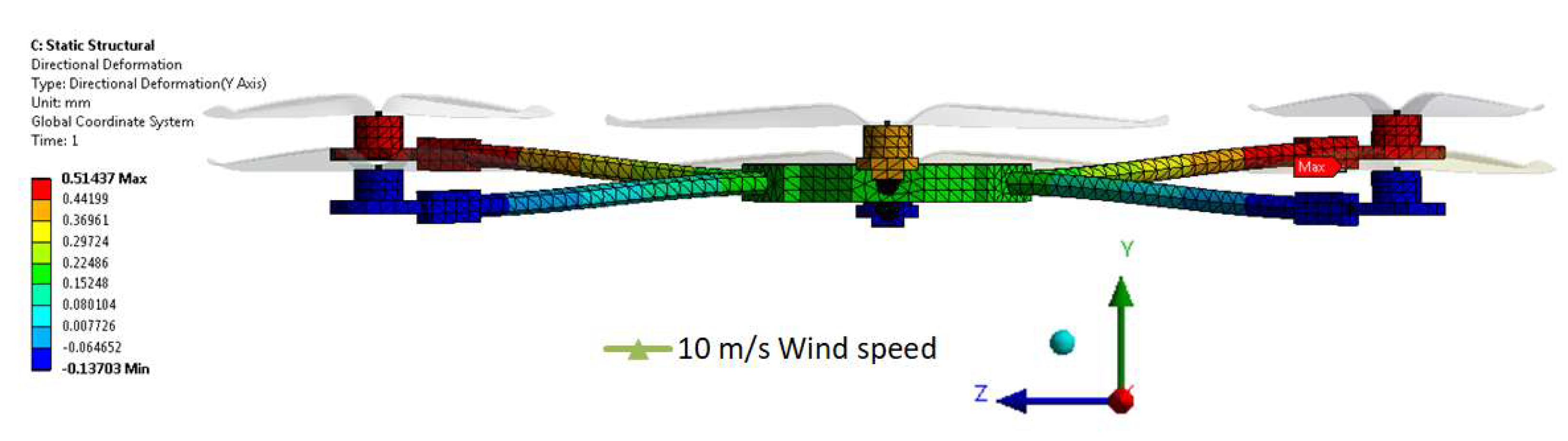
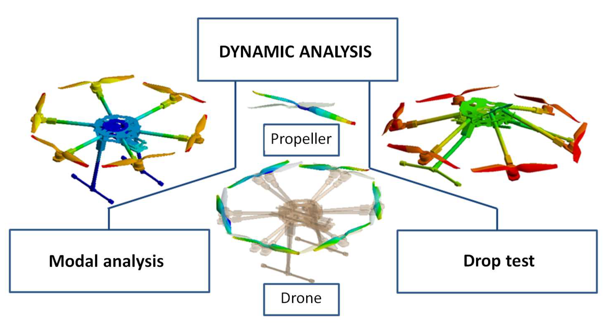
5.2. Dynamic Analysis and Hover Stability
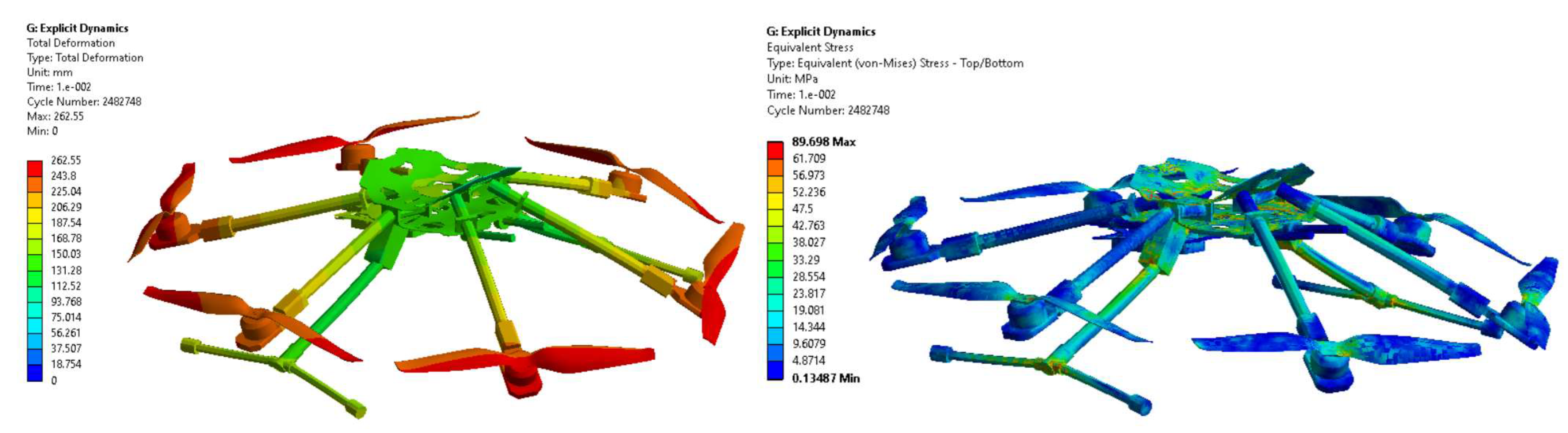
5.3. Hexacopter Drop Test
6. Conclusions and Future Work
Author Contributions
Funding
Institutional Review Board Statement
Informed Consent Statement
Data Availability Statement
Conflicts of Interest
Abbreviations
| AHRS | Attitude and heading reference system |
| AP | Autopilot |
| BLDC | Brushless DC electric motor |
| BVLOS | Beyond visual line-of-sight |
| CAD | Computer-aided design |
| CFD | Computational fluid dynamics |
| DRONE | Dynamic remotely operated navigation equipment |
| EKF | Extended Kalman filter |
| EO/IR | Electro-optical/infra-red |
| ESC | Electronic speed controller |
| FEM | Finite element method |
| FFT | Fast Fourier transforms |
| GIS | Geographic information system |
| GNSS | Global navigation satellite system |
| GPS | Global Positioning System |
| IMU | Inertial measurement unit |
| LIDAR | Light detection and ranging |
| MFD-LPTL | Multisensor fusion data analysis for low-power transmission lines |
| MOSFET | Metal–oxide–semiconductor field-effect transistor |
| PID | Proportional–integral–derivative |
| PPM | Pulse position modulation |
| PWM | Pulse width modulation |
| ROAV | Remotely operated air vehicle |
| ROS | Robotic operating system |
| RPAS | Remotely piloted aircraft system |
| SITL | Software-in-the-loop |
| SPSA | Simultaneous perturbation stochastic approximation |
| UAS | Unmanned aerial system |
| UAV | Unmanned aerial vehicle |
| UGV | Unmanned ground vehicle |
| UUV | Unmanned underwater vehicle |
| VTOL | Vertical takeoff and landing |
References
- Chu, P.H.; Huang, Y.T.; Pi, C.H.; Cheng, S. Autonomous Landing System of a VTOL UAV on an Upward Docking Station Using Visual Servoing. IFAC-PapersOnLine 2022, 55, 108–113. [Google Scholar] [CrossRef]
- Sethi, N.; Ahlawat, S. Low-fidelity design optimization and development of a VTOL swarm UAV with an open-source framework. Array 2022, 14, 100183. [Google Scholar] [CrossRef]
- Patel, T.; Kumar, M.; Abdallah, S. Control of Hybrid Transitioning Morphing-wing VTOL UAV. IFAC-PapersOnLine 2022, 55, 554–559. [Google Scholar] [CrossRef]
- Bahari, M.; Rostami, M.; Entezari, A.; Ghahremani, S.; Etminan, M. A comparative analysis and optimization of two supersonic hybrid SOFC and turbine-less jet engine propulsion system for UAV. Fuel 2022, 319, 123796. [Google Scholar] [CrossRef]
- Bahari, M.; Rostami, M.; Entezari, A.; Ghahremani, S.; Etminan, M. Performance evaluation and multi-objective optimization of a novel UAV propulsion system based on PEM fuel cell. Fuel 2022, 311, 122554. [Google Scholar] [CrossRef]
- Zhou, K.; Liu, Z.; Zhang, X.; Liu, H.; Meng, N.; Huang, J.; Qi, M.; Song, X.; Yan, X. A kW-level integrated propulsion system for UAV powered by PEMFC with inclined cathode flow structure design. Appl. Energy 2022, 328, 120222. [Google Scholar] [CrossRef]
- Lu, S.H.; Kuo, R.J.; Ho, Y.T.; Nguyen, A.T. Improving the efficiency of last-mile delivery with the flexible drones traveling salesman problem. Expert Syst. Appl. 2022, 209, 118351. [Google Scholar] [CrossRef]
- Jung, H.; Kim, J. Drone scheduling model for delivering small parcels to remote islands considering wind direction and speed. Comput. Ind. Eng. 2022, 163, 107784. [Google Scholar] [CrossRef]
- Jeong, H.Y.; Song, B.D.; Lee, S. Optimal scheduling and quantitative analysis for multi-flying warehouse scheduling problem: Amazon airborne fulfillment center. Transp. Res. Part C Emerg. Technol. 2022, 143, 103831. [Google Scholar] [CrossRef]
- Zhai, D.; Wang, C.; Cao, H.; Garg, S.; Hassan, M.M.; Al Qahtani, S.A. Deep neural network-based UAV deployment and dynamic power control for 6G-Envisioned intelligent warehouse logistics system. Future Gener. Comput. Syst. 2022, 137, 164–172. [Google Scholar] [CrossRef]
- Mourtzis, D.; Angelopoulos, J.; Panopoulos, N. UAVs for Industrial Applications: Identifying Challenges and Opportunities from the Implementation Point of View. Procedia Manuf. 2021, 55, 183–190. [Google Scholar] [CrossRef]
- Yuan, C.S.; Cheng, W.H.; Su, S.Y.; Chen, W.H. Field measurement of spatiotemporal distributions of ambient concentrations of volatile organic compounds around a high-tech industrial park using a drone. Atmos. Pollut. Res. 2021, 12, 101187. [Google Scholar] [CrossRef]
- Wang, Y.; Li, Y.; Yin, F.; Wang, W.; Sun, H.; Li, J.; Zhang, K. An intelligent UAV path planning optimization method for monitoring the risk of unattended offshore oil platforms. Process Saf. Environ. Prot. 2022, 160, 13–24. [Google Scholar] [CrossRef]
- Cho, J.; Lim, G.; Biobaku, T.; Kim, S.; Parsaei, H. Safety and Security Management with Unmanned Aerial Vehicle (UAV) in Oil and Gas Industry. Procedia Manuf. 2015, 3, 1343–1349. [Google Scholar] [CrossRef] [Green Version]
- Garcia-Vasquez, A.C.; Mokari, E.; Samani, Z.; Fernald, A. Using UAV-thermal imaging to calculate crop water use and irrigation efficiency in a flood-irrigated pecan orchard. Agric. Water Manag. 2022, 272, 107824. [Google Scholar] [CrossRef]
- Cheng, K.H.; Jiao, J.J.; Luo, X.; Yu, S. Effective coastal Escherichia coli monitoring by unmanned aerial vehicles (UAV) thermal infrared images. Water Res. 2022, 222, 118900. [Google Scholar] [CrossRef] [PubMed]
- Qin, G.; Xu, Y.; Li, F.; Zhou, W.; Li, W.; Zhao, G. Calibration of an airborne γ-ray spectrometer based on an unmanned aerial vehicle using a point source. Ann. Nucl. Energy 2022, 178, 109349. [Google Scholar] [CrossRef]
- Lipovský, P.; Novotnák, J.; Blažek, J. Possible Utilization of Low Frequency Magnetic Fields in Short Range Multirotor UAV Detection System. Transp. Res. Procedia 2022, 65, 106–115. [Google Scholar] [CrossRef]
- Amodu, O.A.; Busari, S.A.; Othman, M. Physical layer aspects of terahertz-enabled UAV communications: Challenges and opportunities. Veh. Commun. 2022, 38, 100540. [Google Scholar] [CrossRef]
- Xie, C.; Yang, C. A review on plant high-throughput phenotyping traits using UAV-based sensors. Comput. Electron. Agric. 2020, 178, 105731. [Google Scholar] [CrossRef]
- Da Silva, S.D.P.; Eugenio, F.C.; Fantinel, R.A.; Amaral, L.D.P.; dos Santos, A.R.; Mallmann, C.L.; dos Santos, F.D.; Pereira, R.S.; Ruoso, R. Modeling and detection of invasive trees using UAV image and machine learning in a subtropical forest in Brazil. Ecol. Inform. 2023, 74, 101989. [Google Scholar] [CrossRef]
- Amarasingam, N.; Ashan Salgadoe, A.S.; Powell, K.; Gonzalez, L.F.; Natarajan, S. A review of UAV platforms, sensors, and applications for monitoring of sugarcane crops. Remote Sens. Appl. Soc. Environ. 2022, 26, 100712. [Google Scholar] [CrossRef]
- Hao, Z.; Li, M.; Yang, W.; Li, X. Evaluation of UAV spraying quality based on 1D-CNN model and wireless multi-sensors system. Inf. Process. Agric. 2022; in press. [Google Scholar] [CrossRef]
- Lin, B.; Xu, J.; Yin, C.; Chen, L.; You, Y.; Hu, L. An ultralight dual-wavelength and dual-beam chemical sensor on small UAV for in-situ determination of phosphate and nitrite in surface water. Sens. Actuators B Chem. 2022, 368, 132235. [Google Scholar] [CrossRef]
- Mumuni, F.; Mumuni, A.; Amuzuvi, C.K. Deep learning of monocular depth, optical flow and ego-motion with geometric guidance for UAV navigation in dynamic environments. Mach. Learn. Appl. 2022, 10, 100416. [Google Scholar] [CrossRef]
- Bauer, P.; Kun, S. Optical flow-based angular rate sensor fault detection on UAVs. IFAC-PapersOnLine 2022, 55, 46–51. [Google Scholar] [CrossRef]
- Stöcker, C.; Bennett, R.; Koeva, M.; Nex, F.; Zevenbergen, J. Scaling up UAVs for land administration: Towards the plateau of productivity. Land Use Policy 2022, 114, 105930. [Google Scholar] [CrossRef]
- Wang, T.; Mei, X.; Alex Thomasson, J.; Yang, C.; Han, X.; Yadav, P.K.; Shi, Y. GIS-based volunteer cotton habitat prediction and plant-level detection with UAV remote sensing. Comput. Electron. Agric. 2022, 193, 106629. [Google Scholar] [CrossRef]
- Tan, Y.; Li, G.; Cai, R.; Ma, J.; Wang, M. Mapping and modelling defect data from UAV captured images to BIM for building external wall inspection. Autom. Constr. 2022, 139, 104284. [Google Scholar] [CrossRef]
- Yap, Y.L.; Toh, W.; Giam, A.; Yong, F.R.; Chan, K.I.; Tay, J.W.S.; Teong, S.S.; Lin, R.; Ng, T.Y. Topology optimization and 3D printing of micro-drone: Numerical design with experimental testing. Int. J. Mech. Sci. 2023, 237, 107771. [Google Scholar] [CrossRef]
- Tolba, M.; Shirinzadeh, B. Generic modeling and control of unbalanced multirotor UAVs. Aerosp. Sci. Technol. 2022, 121, 107394. [Google Scholar] [CrossRef]
- Lee, S.; Chung, W.; Son, H. Online parameter identification framework for a multirotor UAV: Application to an arm stretchable morphing multirotor. Mech. Syst. Signal Process. 2022, 166, 108468. [Google Scholar] [CrossRef]
- Michel, N.; Wei, P.; Kong, Z.; Sinha, A.K.; Lin, X. Modeling and validation of electric multirotor unmanned aerial vehicle system energy dynamics. eTransportation 2022, 12, 100173. [Google Scholar] [CrossRef]
- Lim, D.; Kim, H.; Yee, K. Uncertainty propagation in flight performance of multirotor with parametric and model uncertainties. Aerosp. Sci. Technol. 2022, 122, 107398. [Google Scholar] [CrossRef]
- Zhang, H.; Qi, L.; Wan, J.; Musiu, E.M.; Zhou, J.; Lu, Z.; Wang, P. Numerical simulation of downwash airflow distribution inside tree canopies of an apple orchard from a multirotor unmanned aerial vehicle (UAV) sprayer. Comput. Electron. Agric. 2022, 195, 106817. [Google Scholar] [CrossRef]
- Liu, Z.; Zhang, Y.; Chen, H.; Zhang, Z. Incremental control system design and flight tests of a micro-coaxial rotor UAV. Aerosp. Sci. Technol. 2022, 131, 107979. [Google Scholar] [CrossRef]
- Mishra, A.; Pal, S.; Singh, P. Design and analysis of an Eight Rotor Co-Axial UAV using carbon fiber composites. Mater. Today: Proc. 2022, 68, 1011–1015. [Google Scholar] [CrossRef]
- Liscouët, J.; Pollet, F.; Jézégou, J.; Budinger, M.; Delbecq, S.; Moschetta, J.M. A methodology to integrate reliability into the conceptual design of safety-critical multirotor unmanned aerial vehicles. Aerosp. Sci. Technol. 2022, 127, 107681. [Google Scholar] [CrossRef]
- Darvishpoor, S.; Roshanian, J.; Raissi, A.; Hassanalian, M. Configurations, flight mechanisms, and applications of unmanned aerial systems: A review. Prog. Aerosp. Sci. 2022, 121, 100694. [Google Scholar] [CrossRef]
- Delbecq, S.; Budinger, M.; Ochotorena, A.; Reysset, A.; Defay, F. Efficient Sizing and Optimization of Multirotor Drones Based on Scaling Laws and Similarity Models. Aerosp. Sci. Technol. 2020, 102, 105873. [Google Scholar] [CrossRef]
- Gupta, A.K.; Jha, V.; Gupta, V.K. Design and Development of Remote Controlled Autonomous Synchronic Hexarotor Aerial (ASHA) Robot. Procedia Technol. 2014, 14, 51–58. [Google Scholar] [CrossRef] [Green Version]
- Suprapto, B.Y.; Heryanto, A.; Suprijono, H.; Muliadi, J.; Kusumoputro, B. Design and Development of Heavy-lift Hexacopter for Heavy Payload. In Proceedings of the International Seminar on Application for Technology of Information and Communication (iSemantic), Semarang, Indonesia, 7–8 October 2017; pp. 242–247. [Google Scholar] [CrossRef]
- Setiono, F.Y.; Candrasaputra, A.; Prasetyo, T.B.; Santoso, K.L.B. Designing and Implementation of Autonomous Hexacopter as Unmanned Aerial Vehicle. In Proceedings of the 8th International Conference on Information Technology and Electrical Engineering (ICITEE), Yogyakarta, Indonesia, 5–6 October 2016; pp. 1–5. [Google Scholar] [CrossRef]
- Verbeke, J.; Hulens, D.; Ramon, H.; Goedemé, T.; de Schutter, J. The Design and Construction of a High Endurance Hexacopter suited for Narrow Corridors. In Proceedings of the International Conference on Unmanned Aircraft Systems (ICUAS), Orlando, FL, USA, 27–30 May 2014; pp. 543–551. [Google Scholar]
- Abarca, M.; Saito, C.; Angulo, A.; Paredes, J.A.; Cuellar, F. Design and Development of an Hexacopter for Air Quality Monitoring at High Altitudes. In Proceedings of the 13th IEEE Conference on Automation Science and Engineering (CASE), Xi’an, China, 20–23 August 2017; pp. 1457–1462. [Google Scholar]
- Arellano-Quintana, V.M.; Portilla-Flores, E.A.; Merchan-Cruz, E.A.; Nino-Suarez, P.A. Multirotor Design Optimization Using a Genetic Algorithm. In Proceedings of the International Conference on Unmanned Aircraft Systems (ICUAS), Arlington, VA, USA, 7–10 June 2016; pp. 1313–1318. [Google Scholar]
- Ferrarese, G.; Giulietti, F.; Avanzini, G. Modeling and Simulation of a Quad-Tilt Rotor Aircraft. IFAC Proc. Vol. 2013, 46, 64–70. [Google Scholar] [CrossRef]
- Ryll, M.; Bicego, D.; Franchi, A. Modeling and Control of FAST-Hex: A Fully–Actuated by Synchronized–Tilting Hexacopter. In Proceedings of the IEEE/RSJ International Conference on Intelligent Robots and Systems (IROS), Daejeon, Republic of Korea, 9–14 October 2016; pp. 1689–1694. [Google Scholar]
- Tadokoro, Y.; Ibuki, T.; Sampei, M. Maneuverability Analysis of a Fully-Actuated Hexrotor UAV Considering Tilt Angles and Arrangement of Rotors. IFAC PapersOnLine 2017, 50, 8981–8986. [Google Scholar] [CrossRef]
- Rajappa, S.; Ryll, M.; Bulthoff, H.H.; Franchi, A. Modeling, Control and Design Optimization for a Fully actuated Hexacopter Aerial Vehicle. In Proceedings of the IEEE International Conference on Robotics and Automation (ICRA), Seattle, WA, USA, 26–30 May 2015. [Google Scholar] [CrossRef] [Green Version]
- Köse, O.; Oktay, T. Hexarotor Yaw Flight Control with SPSA PID Algorithm and Morphing. Int. J. Intell. Syst. Appl. Eng. 2022, 10, 216–221. [Google Scholar]
- Mehmood, H.; Nakamura, T.; Johnson, E.N. A Maneuverability Analysis of a Novel Hexacopter UAV Concept. In Proceedings of the International Conference on Unmanned Aircraft Systems (ICUAS), Arlington, VA, USA, 7–10 June 2016. [Google Scholar] [CrossRef]
- Budinger, M.; Reysset, A.; Ochotorena, A.; Delbecq, S. Scaling laws and similarity models for the preliminary design of multirotor drones. Aerosp. Sci. Technol. 2020, 98, 105658. [Google Scholar] [CrossRef]
- Hussein, M.; Nouacer, R. Reference architecture specification for drone systems. Microprocess. Microsyst. 2022, 95, 104705. [Google Scholar] [CrossRef]
- Cao, S.; Fan, Q.; Yu, W.J.; Wang, L.T.; Ni, S.; Chen, J. Multi-Sensor fusion and data analysis for operating conditions of low power transmission lines. Measurement 2022, 190, 110586. [Google Scholar] [CrossRef]
- Severin, T.; Soffker, D. Sensor optimization for altitude estimation of spraying drones in vineyards. IFAC-PapersOnLine 2022, 55, 107–112. [Google Scholar] [CrossRef]
- Pena, P.F.; Ragab, A.R.; Luna, M.A.; Isaac, M.S.A.; Campoy, P. WILD HOPPER: A heavy-duty UAV for day and night firefighting operations. Heliyon 2022, 8, e09588. [Google Scholar] [CrossRef]
- Ravin, K.; Agrawal, A.K. Drone GPS data analysis for flight path reconstruction: A study on DJI, Parrot & Yuneec make drones. Forensic Sci. Int. Digit. Investig. 2021, 38, 301182. [Google Scholar] [CrossRef]
- Sree Ezhil, V.R.; Rangesh Sriram, B.S.; Christopher Vijay, R.; Yeshwant, S.; Sabareesh, R.K.; Dakkshesh, G.; Raffik, R. Investigation on PID controller usage on Unmanned Aerial Vehicle for stability control. Mater. Today: Proc. 2022, 66 Pt 3, 1313–1318. [Google Scholar] [CrossRef]
- Madokoro, H.; Kiguchi, O.; Nagayoshi, T.; Chiba, T.; Inoue, M.; Chiyonobu, S.; Nix, S.; Woo, H.; Sato, K. Development of Drone-Mounted Multiple Sensing System with Advanced Mobility for In Situ Atmospheric Measurement: A Case Study Focusing on PM2.5. Local Distribution, Sensors 2021, 21, 4881. [Google Scholar] [CrossRef]
- Megayanti, M.; Nugraha, Y.P.; Sary, I.P.; Hidayat, E.; Trilaksono, B.R. Modeling and Implementation of Hexacopter Guidance System Using Fuzzy Logic Control Under Wind Disturbance. In Proceedings of the IEEE 8th International Conference on System Engineering and Technology (ICSET), Bandung, Indonesia, 15–16 October 2018; pp. 12–17. [Google Scholar] [CrossRef]
- Sharipov, D.; Abdullaev, Z.; Tazhiev, Z.; Khafizov, O. Implementation of a mathematical model of a hexacopter control system. In Proceedings of the International Conference on Information Science and Communications Technologies (ICISCT), Tashkent, Uzbekistan, 4–6 November 2019; pp. 1–5. [Google Scholar] [CrossRef]
- Toledo, J.; Acosta, L.; Perea, D.; Morales, N. Stability and performance analysis of unmanned aerial vehicles: Quadcopter against Hexrotor. IET Control Theory Appl. 2015, 9, 1190–1196. [Google Scholar] [CrossRef]
- Wen, F.-H.; Hsiao, F.-Y.; Shiau, J.-K. Analysis and Management of Motor Failures of Hexacopter in Hover. Actuators 2021, 10, 48. [Google Scholar] [CrossRef]
- Leishman, R.; Macdonald, J.; McLain, T.; Beard, R. Relative Navigation and Control of a Hexacopter. In Proceedings of the IEEE International Conference on Robotics and Automation, St Paul, MI, USA, 14–18 May 2012; pp. 4937–4942. [Google Scholar]
- Derawi, D.; Salim, N.D.; Azizi, M.; Rahman, A.; Mazlan, S.A.; Zamzuri, H. Modeling, Attitude Estimation, and Control of Hexacopter Micro Aerial Vehicle (MAV). In Proceedings of the IEEE International Conference on Industrial Technology (ICIT), Busan, Republic of Korea, 26 February–1 March 2014; pp. 55–60. [Google Scholar]
- Derawi, D.; Salim, N.D.; Zamzuri, H.; Liu, H.; Azizi, M.; Rahman, A.; Mazlan, S.A. Robust Attitude Controler for Uncertain Hexacopter Micro Aerial Vehicles (MAVs). In Proceedings of the IEEE/RSJ International Conference on Intelligent Robots and Systems (IROS), Chicago, IL, USA, 14–18 September 2014; pp. 4776–4781. [Google Scholar]
- Poksawat, P.; Wang, L. Automatic Tuning of Hexacopter Attitude Control Systems with Experimental Validation. In Proceedings of the 21st International Conference on System Theory, Control and Computing (ICSTCC), Sinaia, Romania, 19–21 October 2017; pp. 753–758. [Google Scholar] [CrossRef]
- Zheng, Y.; Dong, L.; Wang, Q. Multi-Rotor UAV Attitude Calculation Based on Extended Kalman Filter. In Proceedings of the 30th Chinese Control and Decision Conference (CCDC), Shenyang, China, 9–11 June 2018; pp. 478–483. [Google Scholar]
- Benzemrane, K.; Damm, G.; Santosuosso, G.L. Adaptive Observer and Kalman Filtering. In Proceedings of the 17th World Congress, The International Federation of Automatic Control, Seoul, Korea, 6–11 July 2008; pp. 3865–3870. [Google Scholar]
- Benzerrouk, H.; Nebylov, A.; Salhi, H. Quadcopter UAV state estimation based on High-Degree Cubature Kalman filter. IFAC-PapersOnLine 2016, 49, 349–354. [Google Scholar] [CrossRef]
- Neumann, P.P.; Bartholmai, M. Real-time wind estimation on a micro unmanned aerial vehicle using its inertial measurement unit. Sens. Actuators 2015, 235, 300–310. [Google Scholar] [CrossRef]
- Sushchenko, O.A.; Beliavtsev, Y.V. Modelling of Inertial Sensors in UAV Systems. In Proceedings of the IEEE 4th International Conference Actual Problems of Unmanned Aerial Vehicles Developments (APUAVD), Kiev, Ukraine, 17–19 October 2017; pp. 130–133. [Google Scholar] [CrossRef]
- Heise, C.D.; Falconi, G.P.; Holzapfel, F. Hexacopter Outdoor Flight Test Results of an Extended State Observer based Controller. In Proceedings of the IEEE International Conference on Aerospace Electronics and Remote Sensing Technology (ICARES), Yogyakarta, Indonesia, 13–14 November 2014; pp. 26–33. [Google Scholar]
- Dong, W.; Gu, G.Y.; Zhu, X.; Ding, H. High-performance trajectory tracking control of a quadcopter with disturbance observer. Sens. Actuators 2014, 211, 67–77. [Google Scholar] [CrossRef]
- Lee, S.J.; Kim, S.; Johansson, K.H.; Kim, H.J. Robust Acceleration Control of a Hexacopter UAV with a Disturbance Observer. In Proceedings of the IEEE 55th Conference on Decision and Control (CDC), Las Vegas, NV, USA, 12–14 December 2016; pp. 4166–4171. [Google Scholar]
- Seah, C.H.; Inyang, I.J.; Whidborne, J.F. Bilinear Modelling and Attitude Control of a quadcopter. IFAC PapersOnLine 2017, 50, 193–198. [Google Scholar] [CrossRef]
- Herrada, F.J.; García-Martínez, J.; Fraile, A.; Hermanns, L.K.H.; Montáns, F.J. A method for performing efficient parametric dynamic analyses in large finite element models undergoing structural modifications. Eng. Struct. 2017, 131, 625–638. [Google Scholar] [CrossRef]
- Karthik Vinayaga, K.; Vasanthanathan, A.; Nagaraj, P. Finite element modeling of smart piezoelectric beam using ANSYS. Mater. Today Proc. 2018, 5, 7078–7085. [Google Scholar] [CrossRef]
- Ryzhakov, P.; Rossi, R.; Viña, A.; Oñate, E. Modelling and simulation of the sea-landing of aerial vehicles using the Particle Finite Element Method. Ocean. Eng. 2013, 66, 92–100. [Google Scholar] [CrossRef] [Green Version]
- Jiapeng, T.; Ping, X.; Baoyuan, Z.; Bifu, H. A finite element parametric modeling technique of aircraft wing structures. Chin. J. Aeronaut. 2013, 26, 1202–1210. [Google Scholar]
- Papa, U.; Russo, S.; Lamboglia, A.; Del Core, G.; Iannuzzo, G. Health structure monitoring for the design of an innovative UAS fixed wing through inverse finite element method (iFEM). Aerosp. Sci. Technol. 2017, 69, 439–448. [Google Scholar] [CrossRef]
- Felismina, R.; Silva, M.; Mateus, A.; Malça, C. Study on the aerodynamic behavior of a UAV with an applied seeder for agricultural practices. AIP Conf. Proc. 2017, 1836, 020049. [Google Scholar] [CrossRef]
- Lei, Y.; Cheng, M. Aerodynamic performance of a Hex-rotor unmanned aerial vehicle with different rotor spacing. Meas. Control. 2020, 53, 711–718. [Google Scholar] [CrossRef] [Green Version]
- Lei, Y.; Cheng, M. Aerodynamic Performance of Hex-Rotor UAV Considering the Horizontal Airflow. Appl. Sci. 2019, 9, 4797. [Google Scholar] [CrossRef] [Green Version]
- Zheng, Y.; Yang, S.; Liu, X.; Wang, J.; Norton, T.; Chen, J.; Tan, Y. The computational fluid dynamic modeling of downwash flow field for a six-rotor UAV. Front. Agric. Sci. Eng. 2018, 5, 159–167. [Google Scholar] [CrossRef] [Green Version]
- Courant, R.; Friedrichs, K.; Lewy, H. On the partial difference equations of mathematical physics. IBM J. Res. Dev. 1967, 11, 215–234. [Google Scholar] [CrossRef]


| Hexacopter Component | Mass (kg) |
|---|---|
| Frame | 0.833 |
| Brushless electric motor | 0.082 |
| Electronic speed controller | 0.026 |
| 13′′ Propeller | 0.014 |
| Avionics and accessories | 0.763 |
| 12 Ah Battery 12 Ah | 1.080 |
Disclaimer/Publisher’s Note: The statements, opinions and data contained in all publications are solely those of the individual author(s) and contributor(s) and not of MDPI and/or the editor(s). MDPI and/or the editor(s) disclaim responsibility for any injury to people or property resulting from any ideas, methods, instructions or products referred to in the content. |
© 2023 by the authors. Licensee MDPI, Basel, Switzerland. This article is an open access article distributed under the terms and conditions of the Creative Commons Attribution (CC BY) license (https://creativecommons.org/licenses/by/4.0/).
Share and Cite
Stamate, M.-A.; Pupăză, C.; Nicolescu, F.-A.; Moldoveanu, C.-E. Improvement of Hexacopter UAVs Attitude Parameters Employing Control and Decision Support Systems. Sensors 2023, 23, 1446. https://doi.org/10.3390/s23031446
Stamate M-A, Pupăză C, Nicolescu F-A, Moldoveanu C-E. Improvement of Hexacopter UAVs Attitude Parameters Employing Control and Decision Support Systems. Sensors. 2023; 23(3):1446. https://doi.org/10.3390/s23031446
Chicago/Turabian StyleStamate, Mihai-Alin, Cristina Pupăză, Florin-Adrian Nicolescu, and Cristian-Emil Moldoveanu. 2023. "Improvement of Hexacopter UAVs Attitude Parameters Employing Control and Decision Support Systems" Sensors 23, no. 3: 1446. https://doi.org/10.3390/s23031446