
A Feedback Control Sensing System of an Electrorheological Brake to Exert a Constant Pressing Force on an Object
 ,
,
Abstract
:1. Introduction
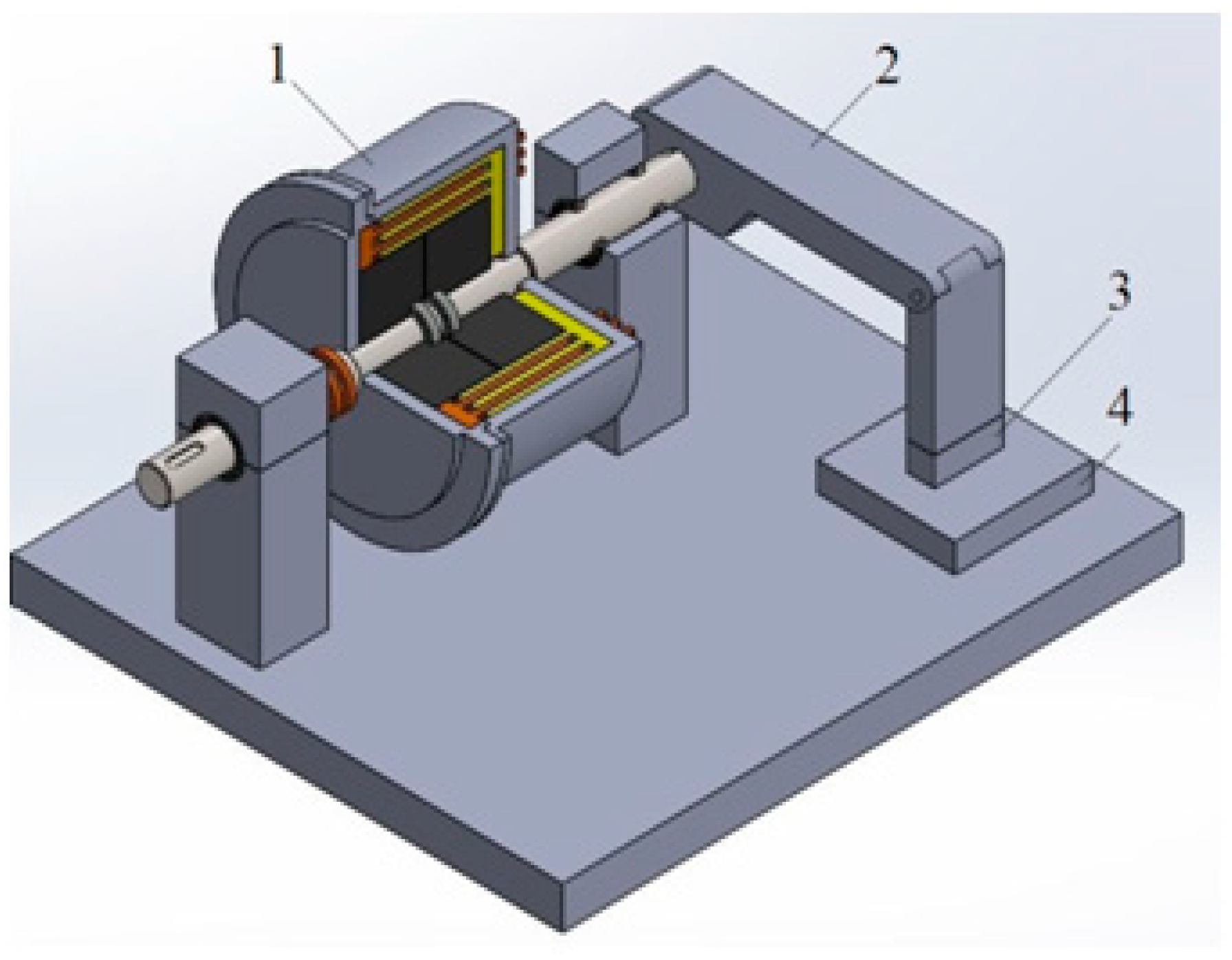
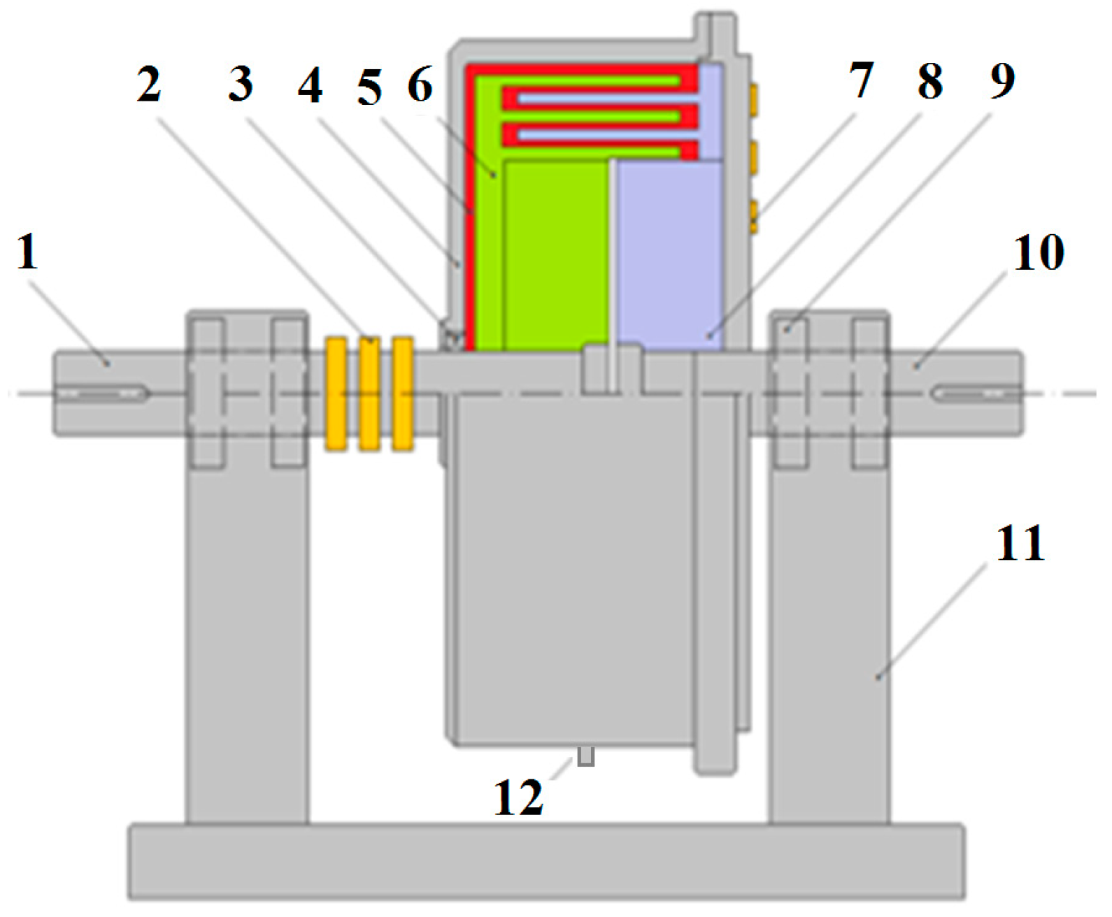
2. Device to Exert a Constant Pressing Force
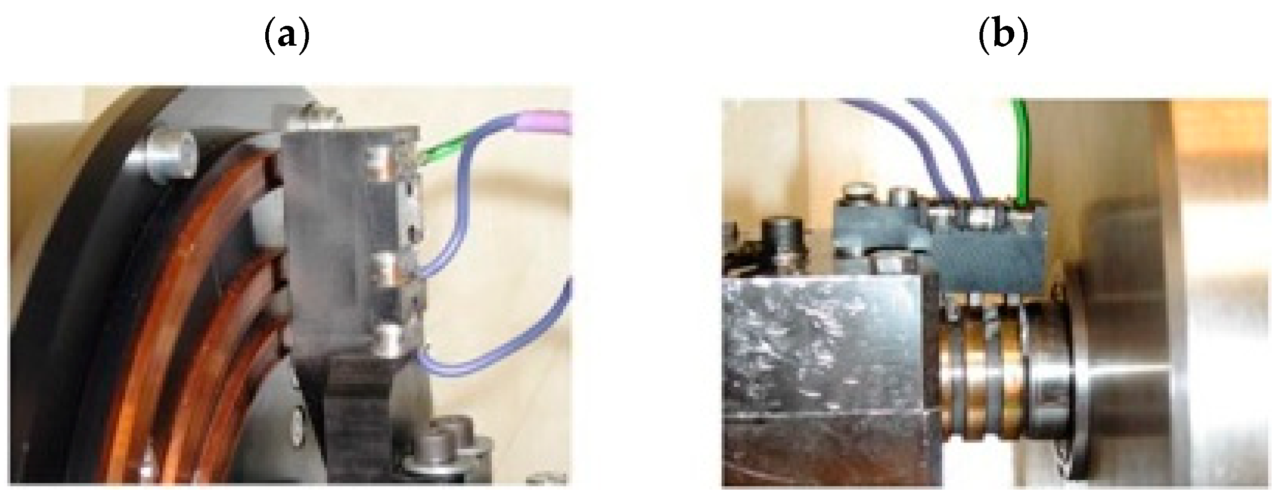
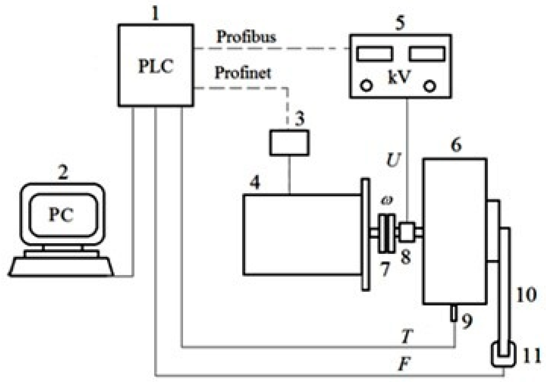
3. Test Bench
4. DECPF Characteristics Research
4.1. Testing of DECPF Characteristics in the Absence of High Electrical Voltage
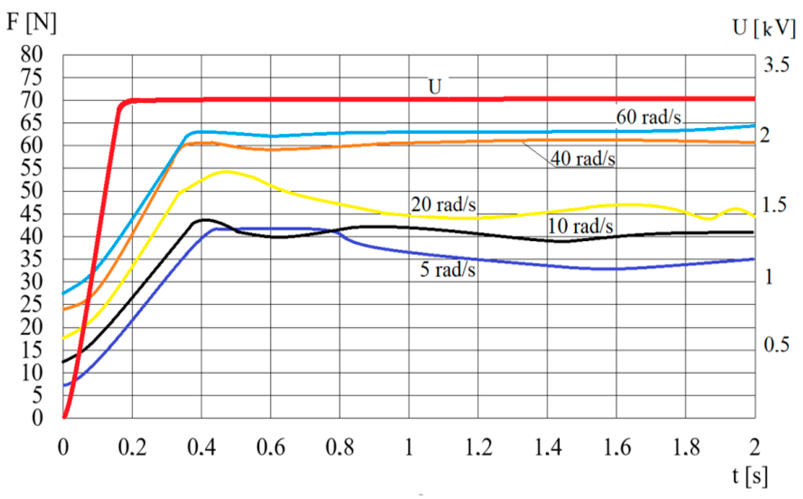
4.2. Testing of DECPF Characteristics in the Presence of High Voltage
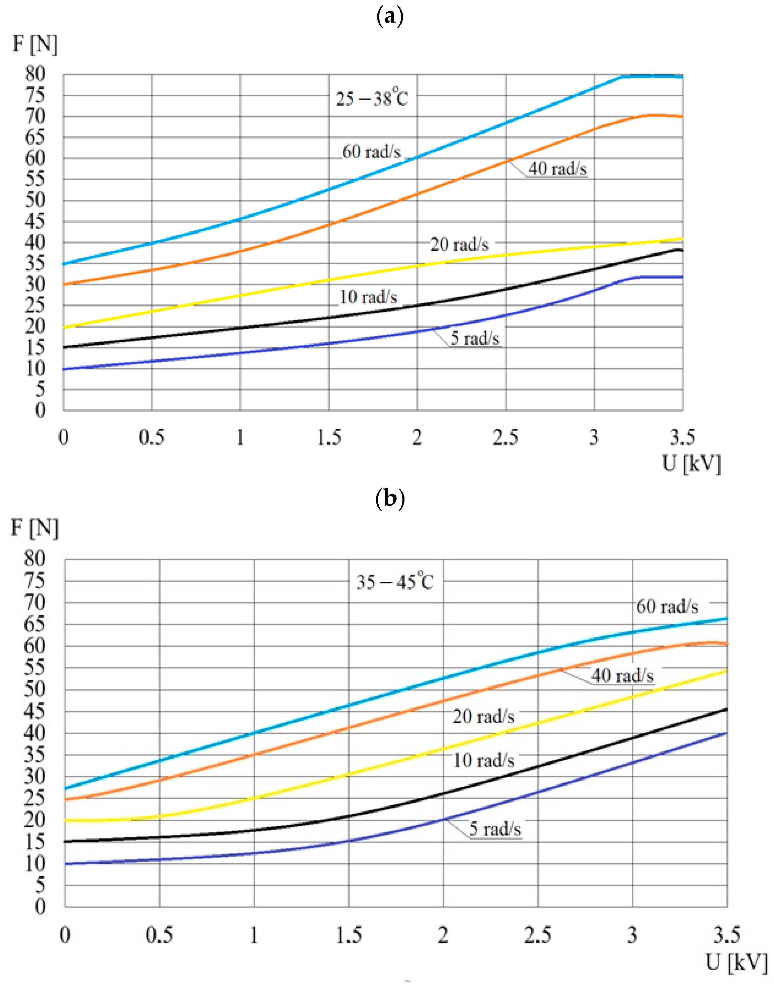
4.3. Research on the Influence of ER Fluid Temperature on DECPF Characteristics
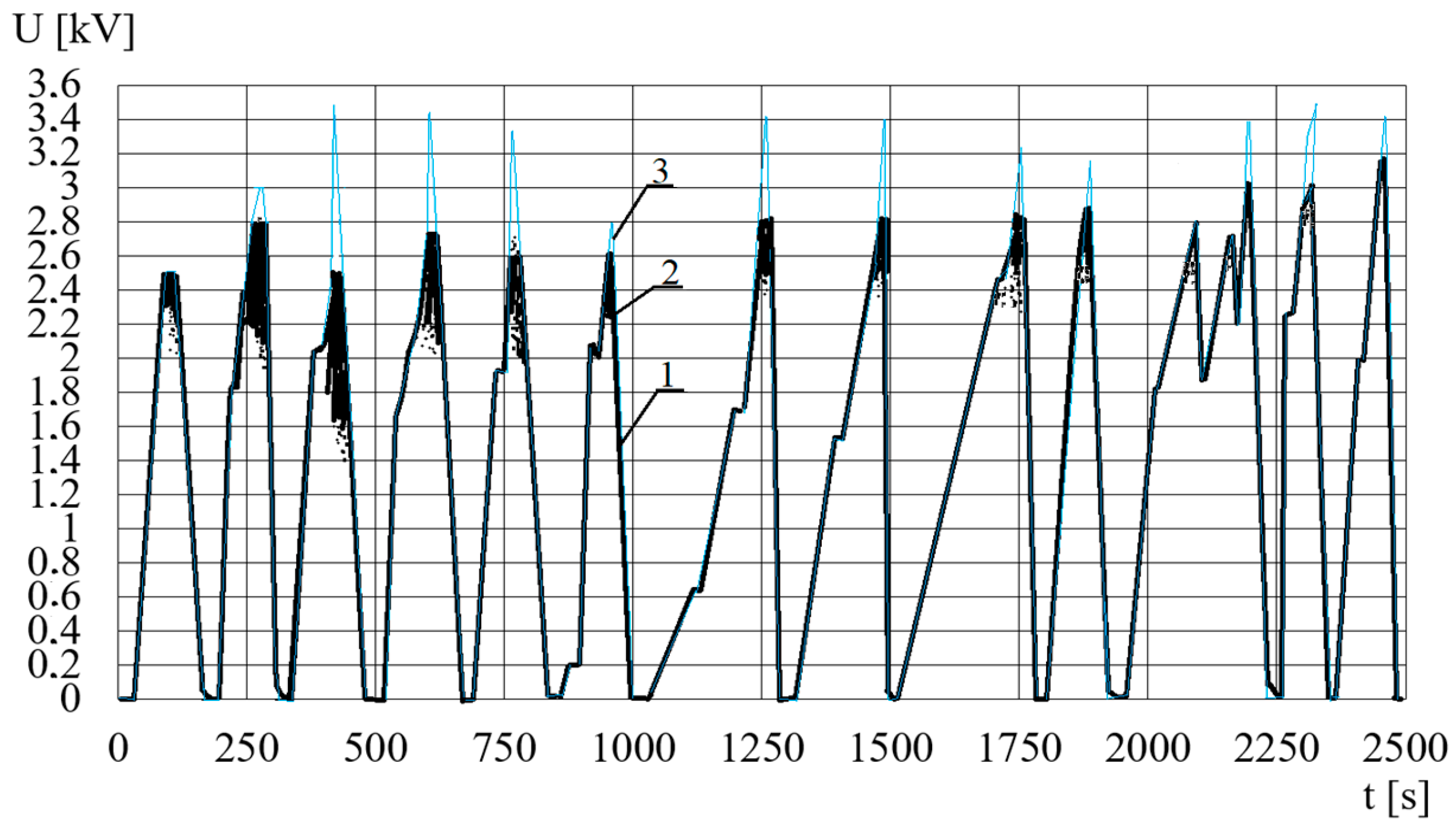
4.4. Research on the Impact of Electrical Breakdowns on the DECPF Characteristics
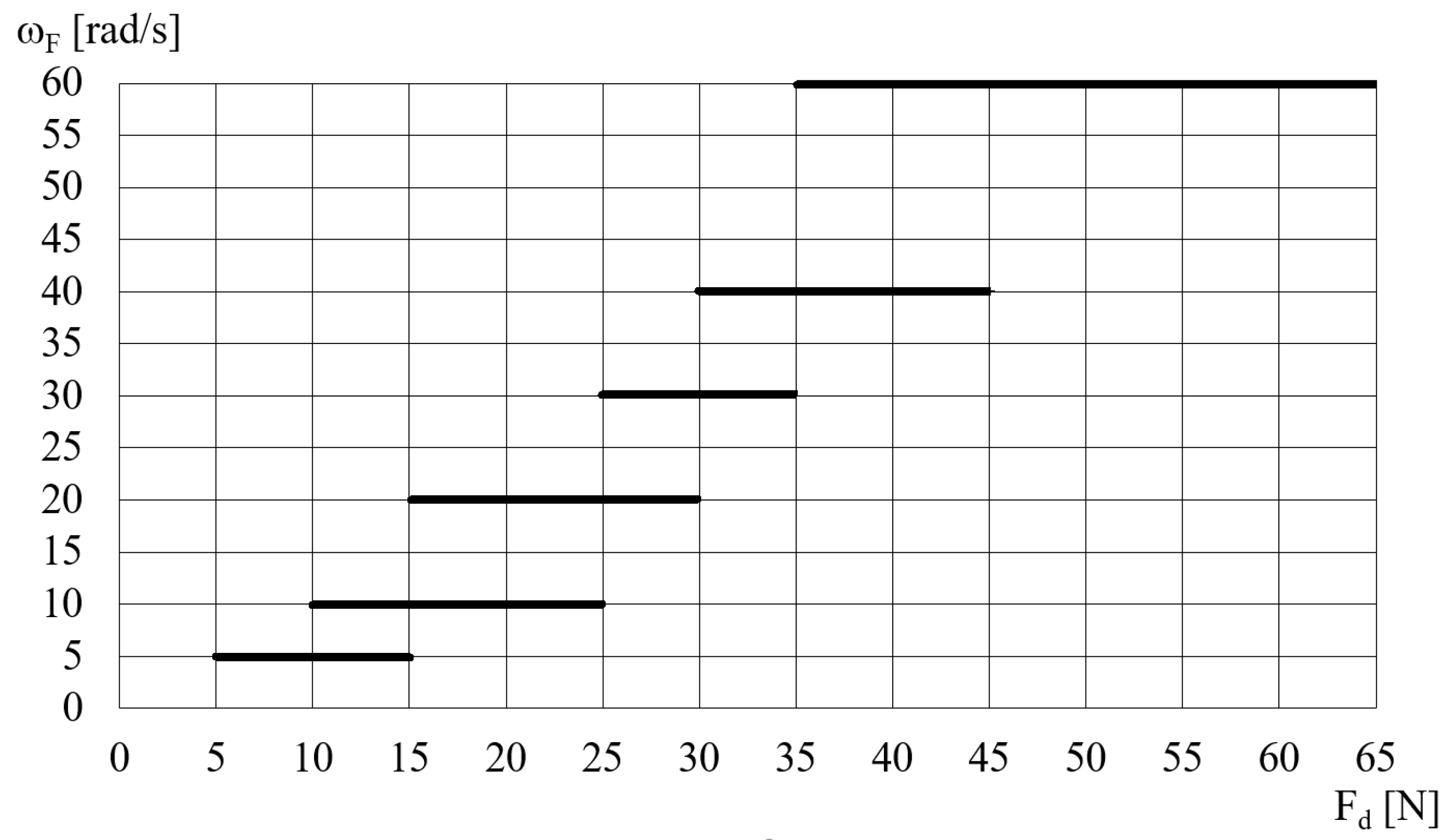
5. Pressing Force Control System
6. Discussion of Research Results
7. Conclusions
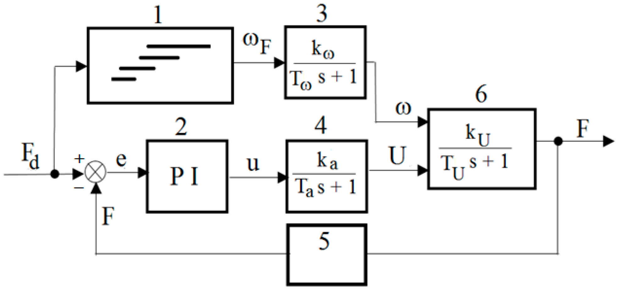
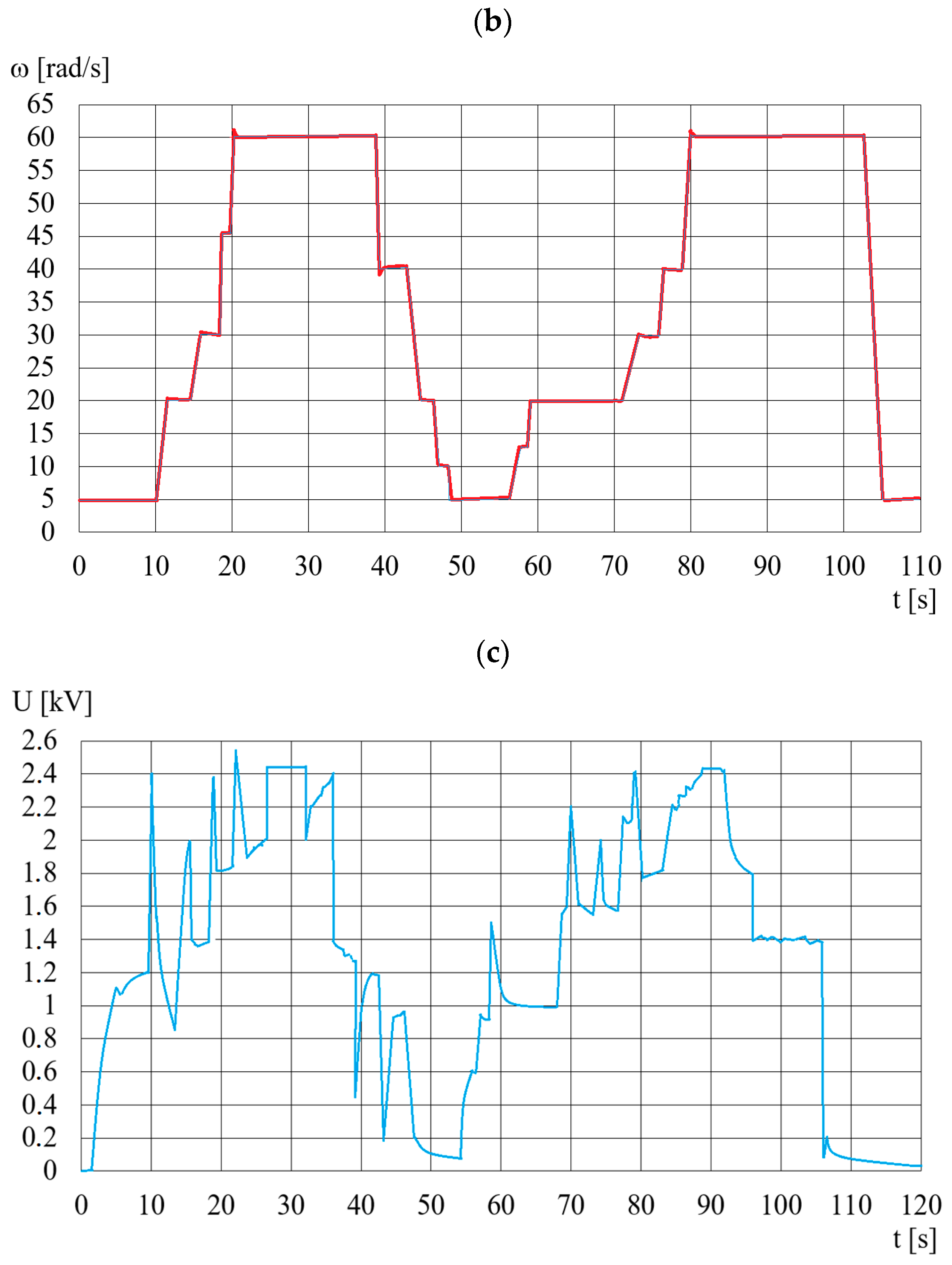
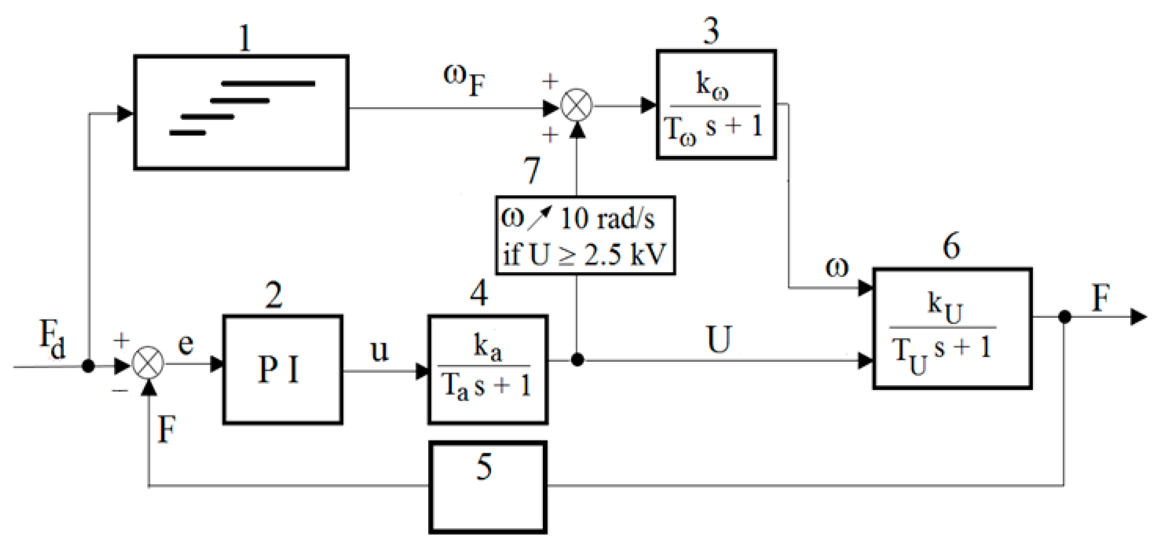
- The random nature of changes in shear stresses within the ER fluid, the significant influence of temperature on the value of these stresses and the occurrence of electrical breakdowns are the reasons why it is necessary to use a feedback control system. The developed feedback control system with the PI controller ensured a controlled pressing force in a wide range could be obtained.
- Due to the intense heat release during the operation of the viscous brake with the ER fluid and due to the increase in the brake temperature (which causes changes in the shear stresses of the ER fluid), it would be beneficial to use an additional brake cooling system in order to stabilize the temperature.
- When designing the DECPF, it should be taken into consideration how the filling degree of the viscous brake with the ER fluid influences the occurrence of electric breakdowns. All working gaps should be completely filled with ER fluid, which would increase the stability of the control system operation.
- Further work on the development of the DECPF structure should focus on designing new control methods to shorten the control time in which several applications of ER fluids associated with proper control methods could be realized in practice.
Author Contributions
Funding
Institutional Review Board Statement
Informed Consent Statement
Data Availability Statement
Conflicts of Interest
References
- Jun, G.; Lamei, X. The study and design of tension controller. In IOP Conference Series: Earth and Environmental Science, 3rd International Conference on Advances in Energy Resources and Environment Engineering, Harbin, China, 8–10 December 2017; IOP Publishing Ltd.: Bristol, UK, 2018; Volume 113, p. 12150. [Google Scholar] [CrossRef]
- Fernández, M.A.; Chang, J. Development of magnetorheological fluid clutch for robotic arm applications. In Proceedings of the 2016 IEEE 14th International Workshop on Advanced Motion Control (AMC), Auckland, New Zealand, 22–24 April 2016; pp. 510–515. [Google Scholar] [CrossRef]
- Choi, S.B.; Cheong, C.C.; Kim, G.W. Feed back control of tension in a moving tape using an ER brak e actuator. Mechatronics 1997, 7, 53–66. [Google Scholar] [CrossRef]
- Kim, K.S.; Choi, S.B.; Cho, M.S. Vibration control of a wire cut discharge machine using ER brake actuator. J. Intell. Mater. Syst. Struct. 2002, 13, 621–624. [Google Scholar] [CrossRef]
- Parveen, K.; Suresh, V.; Vijay, K.J. Electrorheological fluid-from beginning to present. ELK Asia Pac. J. 2017, 1–6. [Google Scholar]
- Qader, I.N.; Kök, M.; Dagdelen, F.; Aydogdu, Y. A review of smart materials researches and applications. El Cezerî J. Sci. Eng. 2019, 6, 755–788. [Google Scholar] [CrossRef]
- Dong, Y.Z.; Seo, Y.; Choi, H.J. Recent development of electro-responsiv e smart electrorheological fluids. Soft Matter 2019, 15, 3473–3486. [Google Scholar] [CrossRef]
- Rozynek, Z.; Mauroy, H.; Castberg, R.C.; Knudsen, K.D.; Fossum, J.O. Dipolar ordering of clay particles in various carrierfluids. Rev. Cub. Fis. 2012, 29, 37–41. [Google Scholar] [CrossRef]
- Yin, J.; Zhao, X. Electrorheology of nanofiber suspensions. Nanoscale Res. Lett. 2011, 6, 256. [Google Scholar] [CrossRef] [Green Version]
- Dong, Y.Z.; Kim, J.N.; Choi, H.J. Graphene oxide and its inorganic composites: Fabrication and electrorheological response. Materials 2019, 12, 2185. [Google Scholar] [CrossRef] [Green Version]
- Mäkelä, K. Characterization and performance of electrorheological fluids based on pine oils. J. Intell. Mater. Syst. Struct. 1999, 10, 609–614. [Google Scholar] [CrossRef]
- Bullough, W.A.; Johnson, A.R.; Tozer, R.; Makin, J. Methodology, performance and problems in ER clutch based positioning mechanisms. Int. J. Mod. Phys. B 1999, 13, 2101–2108. [Google Scholar] [CrossRef]
- Kęsy, Z.; Kęsy, A. Prospects for the control of a torque converter using magnetic fluid. In Proceedings of the IEE International Colloquium on Innovative Actuators for Mechatronic Systems, London, UK, 18 October 1995; Volume 170, pp. 10/1–10/3. [Google Scholar] [CrossRef]
- Kęsy, Z.; Musiałek, I.; Choi, S.-B. Design optimization of a hydrodynamic brake with an electrorheological fluid. Appl. Sci. 2023, 13, 1089. [Google Scholar] [CrossRef]
- Kęsy, Z.; Mędrek, G.; Olszak, A.; Osowski, K.; Kęsy, A. Electrorheological fluid based clutches and brake. Encycl. Smart Mater. 2022, 5, 171–186. [Google Scholar] [CrossRef]
- Musiałek, I.; Migus, M.; Osowski, K.; Olszak, A.; Kęsy, Z.; Kęsy, A.; Kim, G.W.; Choi, S.B. Analysis of a combined clutch with an electrorheological fluid. Smart Mater. Struct. 2020, 29, 087006. [Google Scholar] [CrossRef]
- Musiałek, I.; Kesy, Z.; Kęsy, A.; Kim, G.W.; Choi, S.B. Mathematical modelling and experimental validation of hybrid clutch combined with two modes: Hydraulic and electrorheological fluid mode. Smart Mater. Struct. 2020, 30, 017002. [Google Scholar] [CrossRef]
- Wereley, N.M.; Lindler, J.; Rosenfeld, N.; Choi, Y.T. Biviscous damping behavior in electrorheological shock absorbers. Smart Mater. Struct. 2004, 13, 743–752. [Google Scholar] [CrossRef]
- Choi, S.B. Performance comparison of vehicle suspensions featuring two different electrorheological shock absorbers. Proc. Inst. Mech. Eng. D J. Automob. Eng. 2003, 217, 999–1010. [Google Scholar] [CrossRef]
- Rosenfeld, N.C.; Wereley, N.M. Volume-constrained optimization of magnetorheological and electrorheological valves and dampers. Smart Mater. Struct. 2004, 13, 1303–1313. [Google Scholar] [CrossRef]
- Choi, S.B.; Choi, W.Y. Position control of a cylinder using a hydraulic bridge circuit with ER valves. J. Dyn. Sys. Meas. Control 2000, 122, 201–209. [Google Scholar] [CrossRef]
- Berg, C.D.; Evans, L.F.; Kermode, P.R. Composite structure analysis of a hollow cantilever beam filled with electro-rheologicalfluid. J. Intell. Mater. Struct. 1996, 7, 494–502. [Google Scholar] [CrossRef]
- Choi, Y.T.; Wereley, N.M. Vibration control of a landing gear system featuring electrorheological/magnetorheological fluids. J. Aircr. 2003, 40, 432–439. [Google Scholar] [CrossRef]
- Radice, I.; Bergmann, J.H.M. Conceptual exploration of a gravity-assisted electrorheological fluid-based gripping methodology for assistive technology. Bio-Des. Manuf. 2019, 2, 145–152. [Google Scholar] [CrossRef] [Green Version]
- Phung, H.; Nguyen, C.T.; Jung, H.; Nguyen, T.D.; Choi, H.R. Bidirectional tactile display driven by electrostatic dielectric elastomer actuator. Smart Mater. Struct. 2020, 29, 035007. [Google Scholar] [CrossRef]
- Olszak, A.; Osowski, K.; Kesy, A.; Kesy, Z. Experimental researches of hydraulic clutches with smart fluids. Int. Rev. Mech. Eng. 2016, 10, 364–372. [Google Scholar] [CrossRef]
- Tan, K.P.; Stanway, R.; Bullough, W.A. Braking responses of inertia/load by using an electro-rheological (ER) brake. Mechatronics 2007, 17, 277–289. [Google Scholar] [CrossRef]
- Choi, S.B.; Yook, J.Y.; Choi, M.K.; Nguyen, Q.H.; Lee, Y.S.; Han, M.S. Speed control of DC motor using electrorheological brake system. J. Intell. Mater. Syst. Struct. 2007, 18, 1191–2007. [Google Scholar] [CrossRef]
- Nikitczuk, J.; Weinberg, B.; Mavroidis, C. Control of electro-rheological fluid based torque generation components for use in active rehabilitation devices. Smart Mater. Struct. 2007, 16, 418–428. [Google Scholar] [CrossRef]
- Tian, Y.; Yu, H.; Meng, Y.; Wen, S. A prototype of an exercising bicycle based on electrorheological fluids. J. Intell. Mater. Syst. Struct. 2006, 17, 807–811. [Google Scholar] [CrossRef]
- Togawa, T.; Tachibana, T.; Tanaka, Y.; Peng, J. Hydro-disk-type of electrorheological brakes for small mobile robots. Int. J. Hydromechatronics 2021, 4, 99–115. [Google Scholar] [CrossRef]
- Papadopoulos, C.A. Brakes and clutches using ER fluids. Mechatronics 1998, 8, 719–726. [Google Scholar] [CrossRef]
- Olszak, A.; Osowski, K.; Motyl, P.; Mędrek, G.; Zwolak, J.; Kęsy, A.; Kęsy, Z.; Choi, S.B. Selection of materials used i nviscous clutch with ER fluid working in special conditions. Front. Mater. 2019, 6, 139. [Google Scholar] [CrossRef]
- Żurowski, W.; Osowski, K.; Mędrek, G.; Musiałek, I.; Kęsy, A.; Kęsy, Z.; Choi, S.B. Optimization of viscotic clutch with electrorheological fluid. Smart Mater. Struct. 2022, 31, 095035. [Google Scholar] [CrossRef]
- Nakamura, T.; Saga, N.; Nakazawa, M. Variable viscous control of a homogeneus ER fluid device considering its dynamic charakteristics. Mechatronics 2004, 14, 55–68. [Google Scholar] [CrossRef]
- Nikitczuk, J.; Weinberg, B.; Canavan, P.K. Active knee rehabilitation orthotic device with variable damping characteristics implemented via an electrorheological fluid. IEEE/ASME Trans. Mechatron. 2011, 15, 952–960. [Google Scholar] [CrossRef]
- Nikitczuk, J.; Das, A.; Vyas, H.; Weinberg, B.; Mavroidis, C. Adaptive torque control of electro-rheological fluid brakes used in active knee rehabilitation devices. In Proceedings of the 2006 IEEE International Conference on Robotics and Automation, 2006. ICRA 2006, Orlando, FL, USA, 15–19 May 2006; pp. 393–399. [Google Scholar] [CrossRef]
- Choi, S.B.; Lee, D.Y. Rotational motion control of awashing machine using electro rheological clutches and brakes. Proc. Inst. Mech. Eng. Part C 2005, 219, 627–637. [Google Scholar] [CrossRef]
- Emerson Industrail Automation: User Guide Unidrive SP, Model sizes 0 to 6. Universal Variable Speed AC Drive for Induction and Servo Motors, Part Number: 0471-0000-12. 2008; 12.
- Emerson Industrail Automation: User Guide SM-PROFINET, Part Number: 0471-0163-03. 2012; 3.
- Nakamura, T.; Saga, N.; Nakazawa, M. Thermal effects of a homogeneus ER fluid device. J. Intell. Mater. Syst. Struct. 2003, 14, 87–91. [Google Scholar] [CrossRef]
- Ziąbska, E.; Duchowski, J.; Olszak, A.; Osowski, K.; Kęsy, A.; Kesy, Z.; Choi, S.B. Wear forms of heterogeneous electro-rheological fluids working in a hydraulic clutch system. Smart Mater. Struct. 2017, 26, 095032. [Google Scholar] [CrossRef]
- Jędrzykiewicz, Z. Control Theory of One-Dimensional Systems; AGH Publishing: Kraków, Poland, 2004. (In Polish) [Google Scholar]
- Siemens Industry: Sinamics/SimoticsSinamics v90, SimoticsS-1FL6; Operating Instructions. A5E37208830-003; Siemens: Nürnberg, Germany, May 2014.


| Parameter | Unit | Value |
|---|---|---|
| Outer radius | mm | 120 |
| Width | mm | 110 |
| Number of cylinders in the driving part | - | 3 |
| Number of cylinders in the driven part | - | 2 |
| Number of working gaps | - | 5 |
| Width of the gap between the cylinders | mm | 1.0 |
| Lever length | mm | 250 |
| ERF#6 fluid volume | cm3 | 395 |
| Parameter | Unit |
|---|---|
| Solid phase | Sulfonated resin |
| Size of solid particles | 10 μm |
| The base oil | Silicon oil |
| Dynamic viscosity at 20 °C | μ = 65 mPa·s |
| Density | ρ = 1.074 g cm−3 |
| Share of the solid phase by volume | φo = 35% |
| Yield stress at 2.5 kV and 20 °C | τ0 = 1.8 kPa |
| Type | Model | Producer |
|---|---|---|
| PLC | 6ES7-151-8AB01-0ABO | Siemens |
| Electric motor driver—Inverter | Unidrive SP 14 × 06 | Emerson Industrial Automation |
| Invertercommunicationcard | SM-Profinet | Emerson Industrial Automation |
| Inductive motor | 3SKg 132-4, 5.5 kW | Tamel |
| PC computer | COMPAQ DC7900 | Compaq |
| High-voltage power supply | HCP 3500-350 | Fug |
| Force sensor | KMB19-K-100N 0000-D | P.P.H. Wobit E.K.J. |
| Temperature sensor | Heraeus M222 | Conrad Electronic |
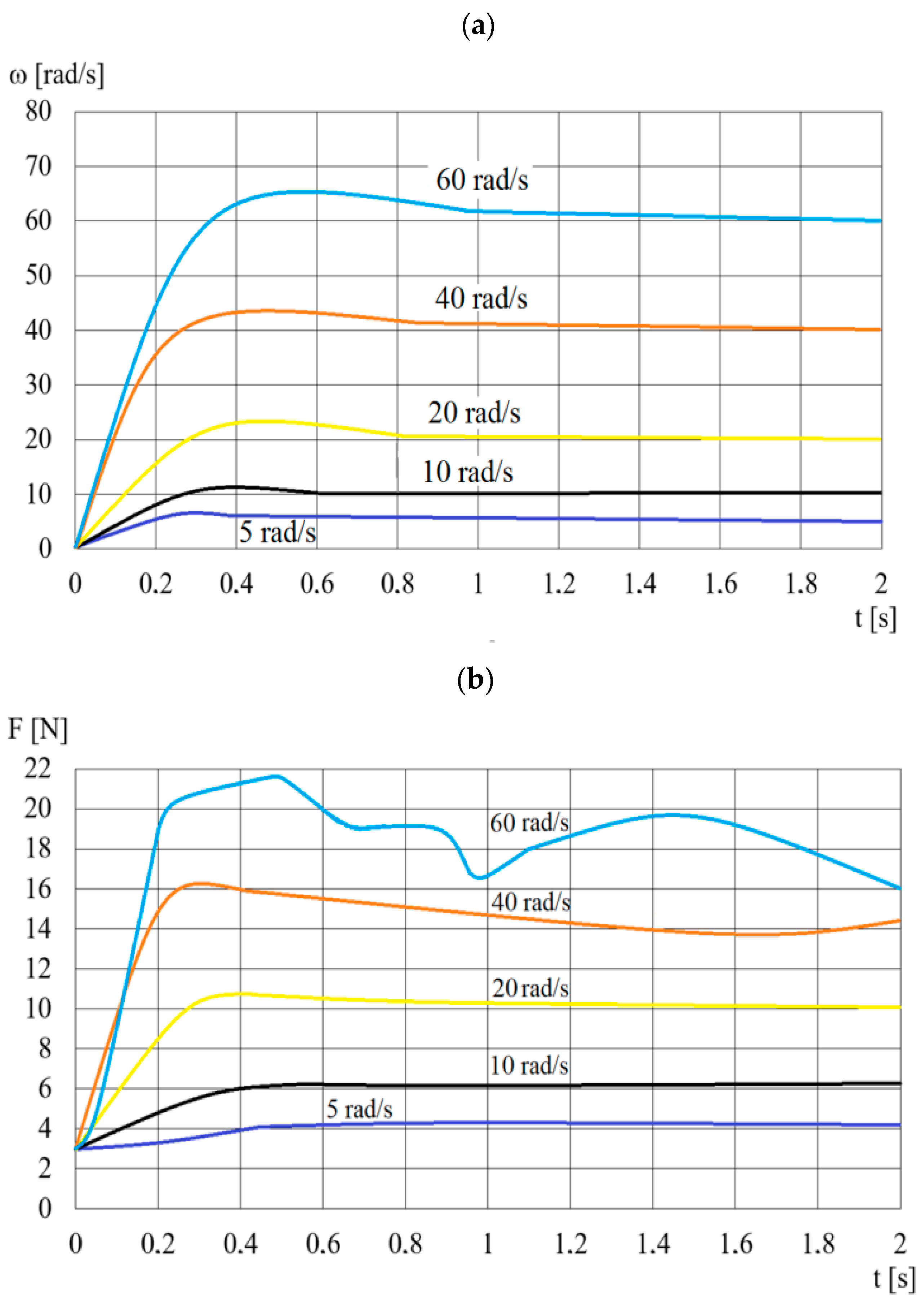
| ω (rad/s) | Maximum F (N) | Tω (s) | kω (N/(rad/s)) |
|---|---|---|---|
| 5 | 4.56 | 0.10 | 0.90 |
| 10 | 6.79 | 0.20 | 0.70 |
| 20 | 10.85 | 0.31 | 0.53 |
| 40 | 16.98 | 0.30 | 0.35 |
| 60 | 21.70 | 0.30 | 0.30 |
| ω [rad/s] | F [N] for 0 kV | F [N] for 3.5 kV | ΔF [N] | ΔF [%] |
|---|---|---|---|---|
| 10 | 5.82 | 38.05 | 32.23 | 554 |
| 20 | 10.62 | 45.93 | 35.31 | 332 |
| 30 | 13.37 | 49.05 | 35.68 | 267 |
| 40 | 16.99 | 45.72 | 28.73 | 169 |
| 50 | 20.67 | 54.91 | 34.24 | 166 |
| 60 | 24.99 | 58.23 | 33.24 | 133 |
| 70 | 29.81 | 58.81 | 29.00 | 97 |
| 80 | 33.12 | 62.21 | 29.09 | 88 |
| 90 | 36.34 | 61.33 | 24.99 | 69 |
| ω (rad/s) | Maximum F (N) | TU | kU (N/kV) |
|---|---|---|---|
| 5 | 40.23 | 0.29 | 14.0 |
| 10 | 43.17 | 0.30 | 16.2 |
| 20 | 52.82 | 0.24 | 18.0 |
| 40 | 59.11 | 0.25 | 24.0 |
| 60 | 62.06 | 0.22 | 25.2 |
| ω (rad/s) | Ub (kV) | F (N) |
|---|---|---|
| 5 | 2.4 | 28.28 |
| 10 | 2.4 | 49.12 |
| 15 | 2.5 | 48.25 |
| 20 | 2.5 | 50.64 |
| 25 | 2.5 | 50.35 |
| 30 | 2.6 | 61.11 |
| 35 | 2.7 | 65.35 |
| 40 | 2.7 | 60.91 |
| 45 | 2.8 | 57.36 |
| 50 | 2.8 | 58.02 |
| 55 | 2.8 | 52.23 |
| 60 | 3.4 | 63.87 |
| Method | kP | kI |
|---|---|---|
| Ziegler–Nichols firstmethod | 0.02 | 0.0337 |
| Ziegler–Nichols secondmethod | 0.09 | 0.1355 |
| Manual setting correction | 0.05 | 0.2000 |
Disclaimer/Publisher’s Note: The statements, opinions and data contained in all publications are solely those of the individual author(s) and contributor(s) and not of MDPI and/or the editor(s). MDPI and/or the editor(s) disclaim responsibility for any injury to people or property resulting from any ideas, methods, instructions or products referred to in the content. |
© 2023 by the authors. Licensee MDPI, Basel, Switzerland. This article is an open access article distributed under the terms and conditions of the Creative Commons Attribution (CC BY) license (https://creativecommons.org/licenses/by/4.0/).
Share and Cite
Spotowski, T.; Osowski, K.; Musiałek, I.; Olszak, A.; Kęsy, A.; Kęsy, Z.; Choi, S. A Feedback Control Sensing System of an Electrorheological Brake to Exert a Constant Pressing Force on an Object. Sensors 2023, 23, 6996. https://doi.org/10.3390/s23156996
Spotowski T, Osowski K, Musiałek I, Olszak A, Kęsy A, Kęsy Z, Choi S. A Feedback Control Sensing System of an Electrorheological Brake to Exert a Constant Pressing Force on an Object. Sensors. 2023; 23(15):6996. https://doi.org/10.3390/s23156996
Chicago/Turabian StyleSpotowski, Tomasz, Karol Osowski, Ireneusz Musiałek, Artur Olszak, Andrzej Kęsy, Zbigniew Kęsy, and SeungBok Choi. 2023. "A Feedback Control Sensing System of an Electrorheological Brake to Exert a Constant Pressing Force on an Object" Sensors 23, no. 15: 6996. https://doi.org/10.3390/s23156996