
Characterization of Stromatolite Organic Sedimentary Structure Based on Spectral Image Fusion
 , ,
, ,  ,
, 
Abstract
:1. Introduction
2. Materials and Methods
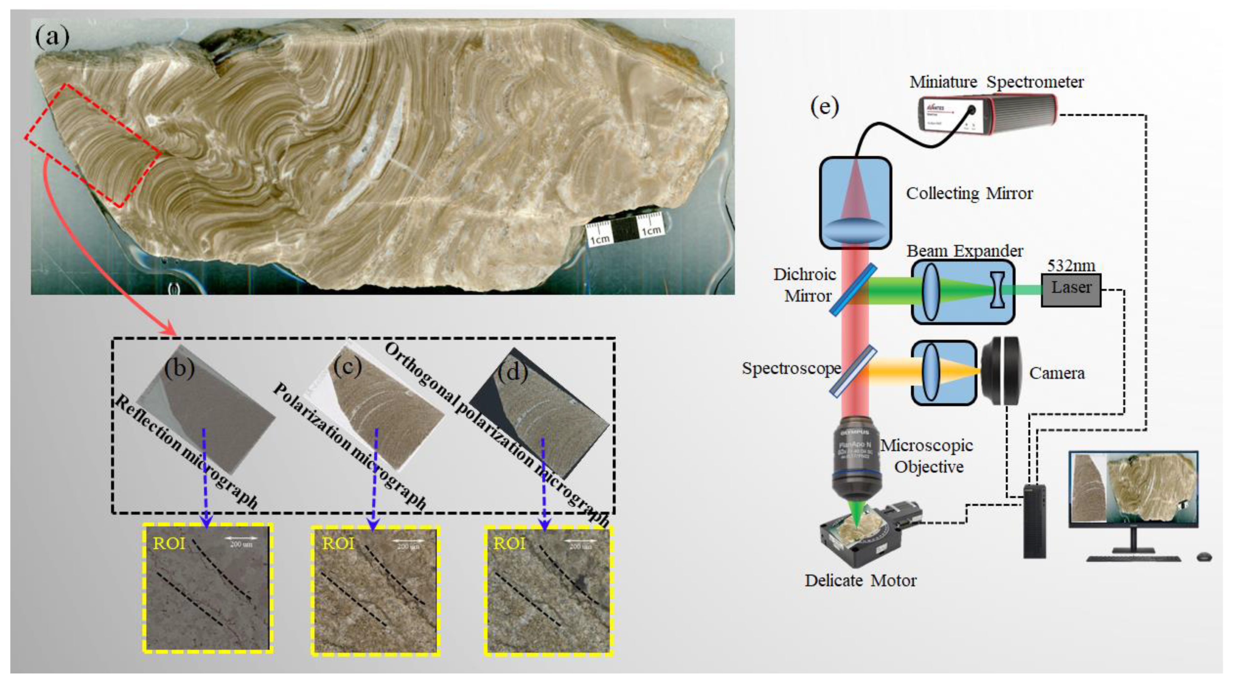
2.1. Sample Description and Preparation
2.2. Experimental Device
2.3. Spectral Data Pre-Processing
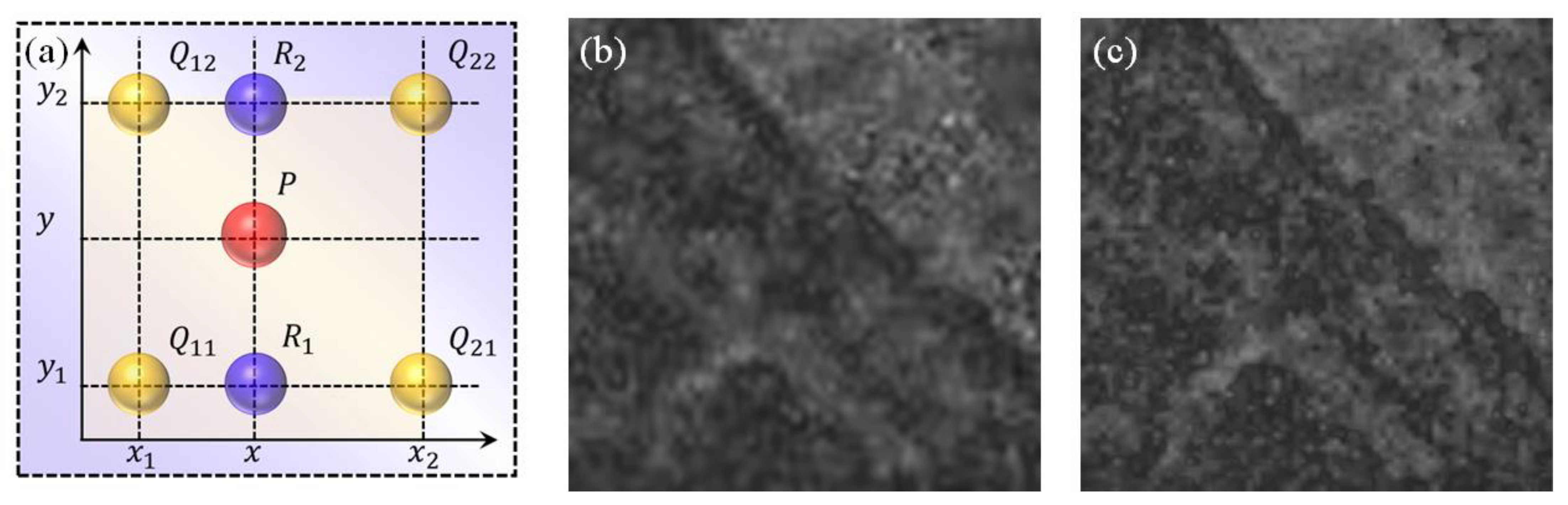
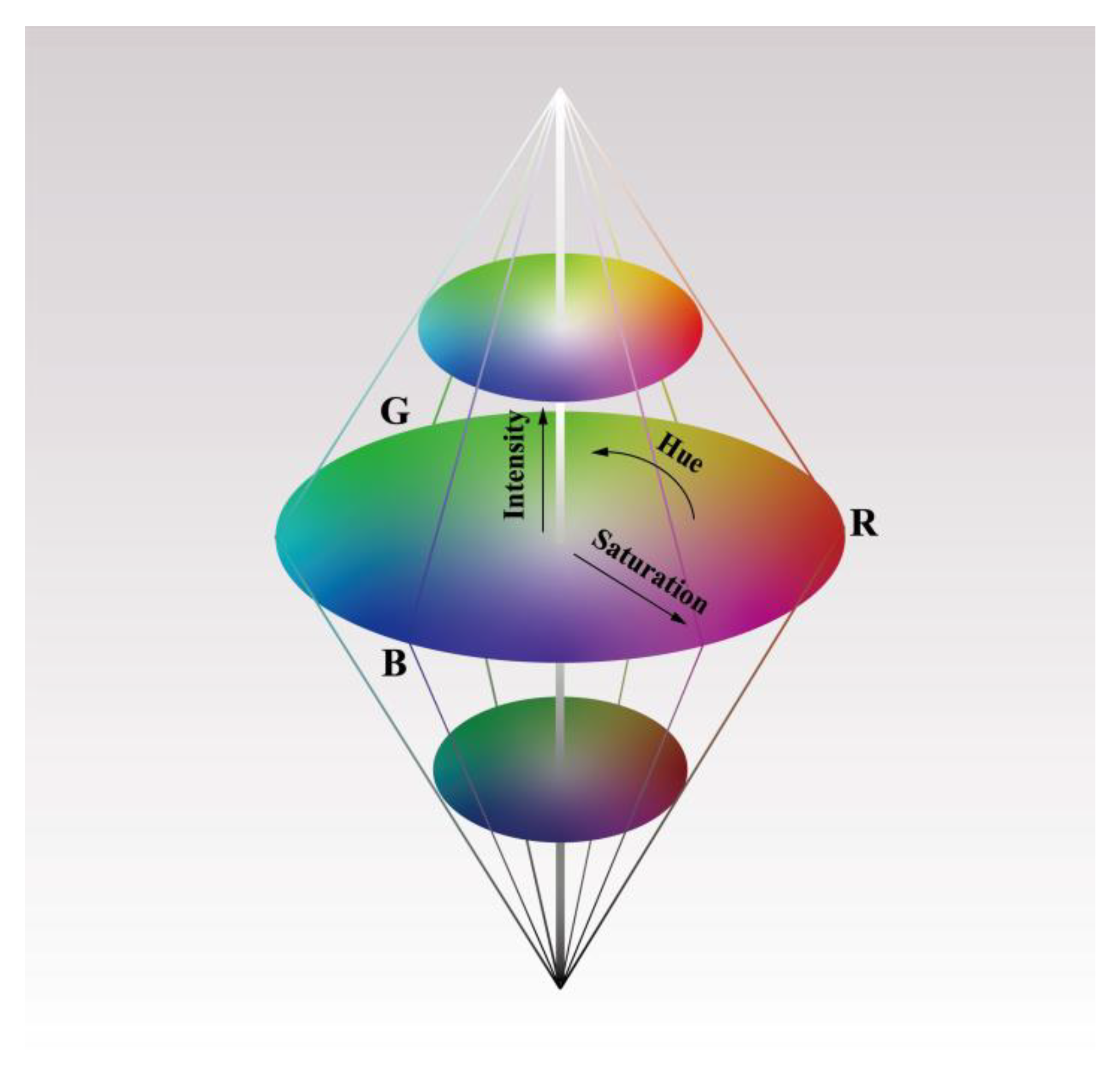
2.4. Algorithm
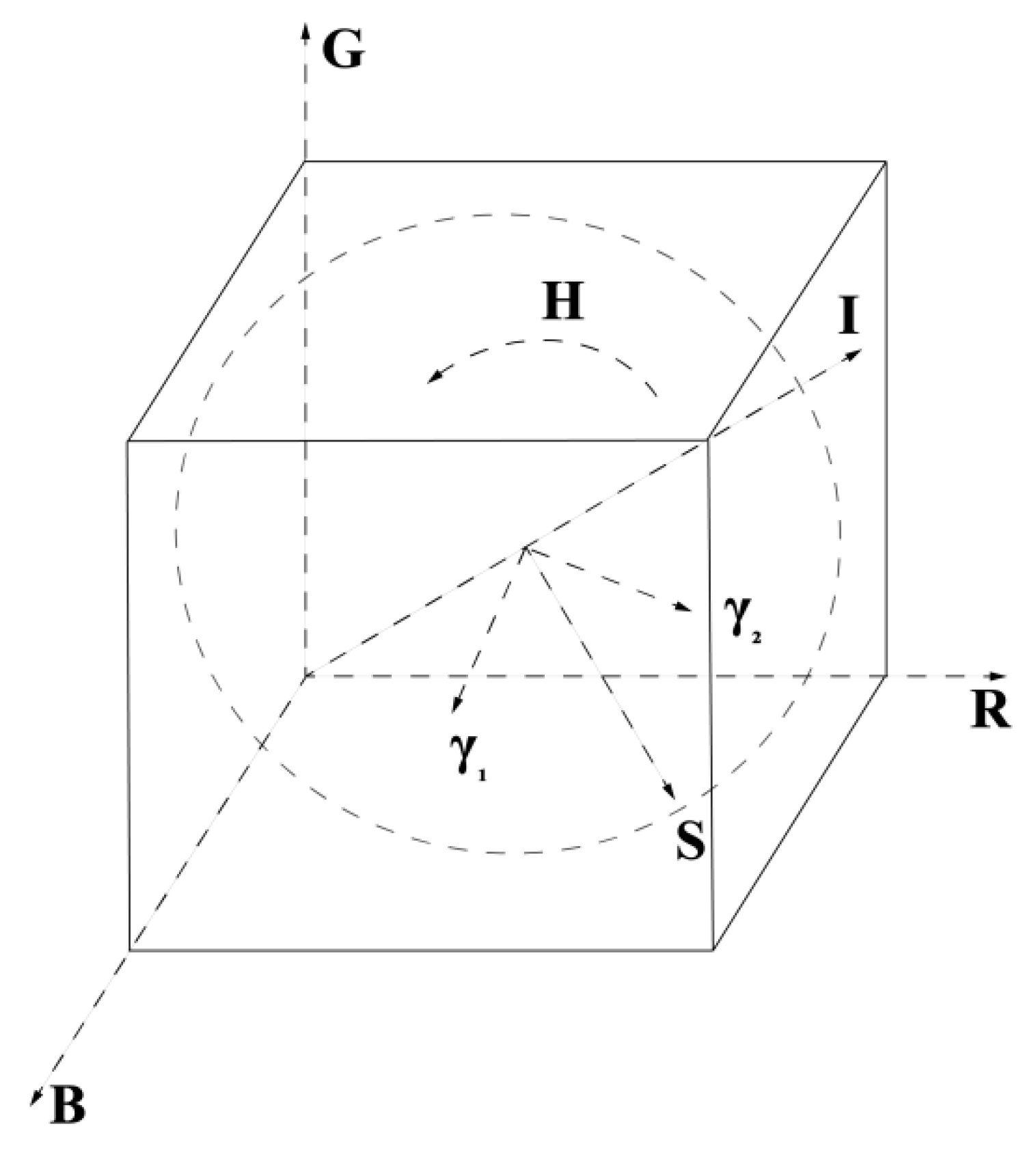
BI-IHS Model
3. Results
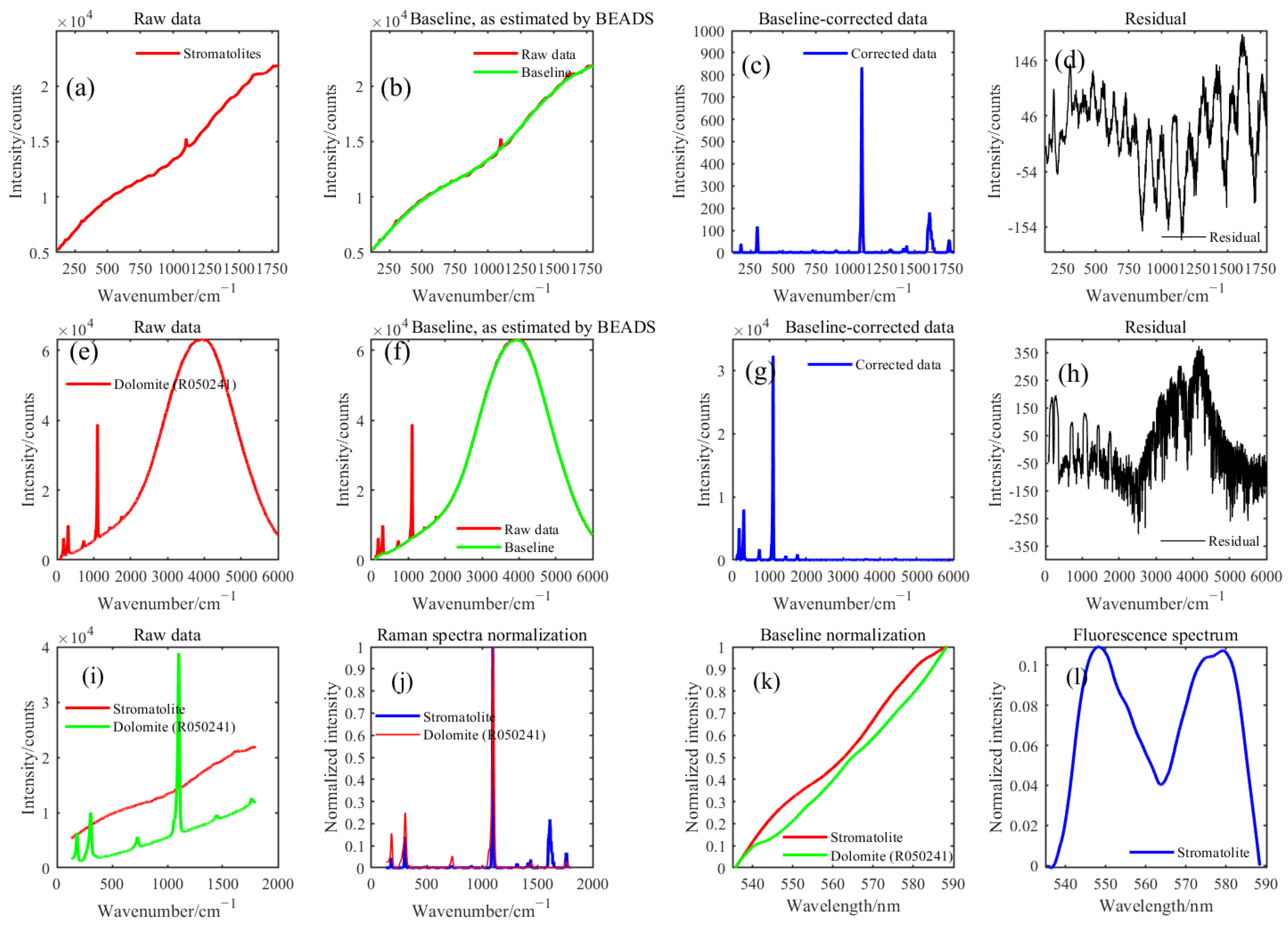
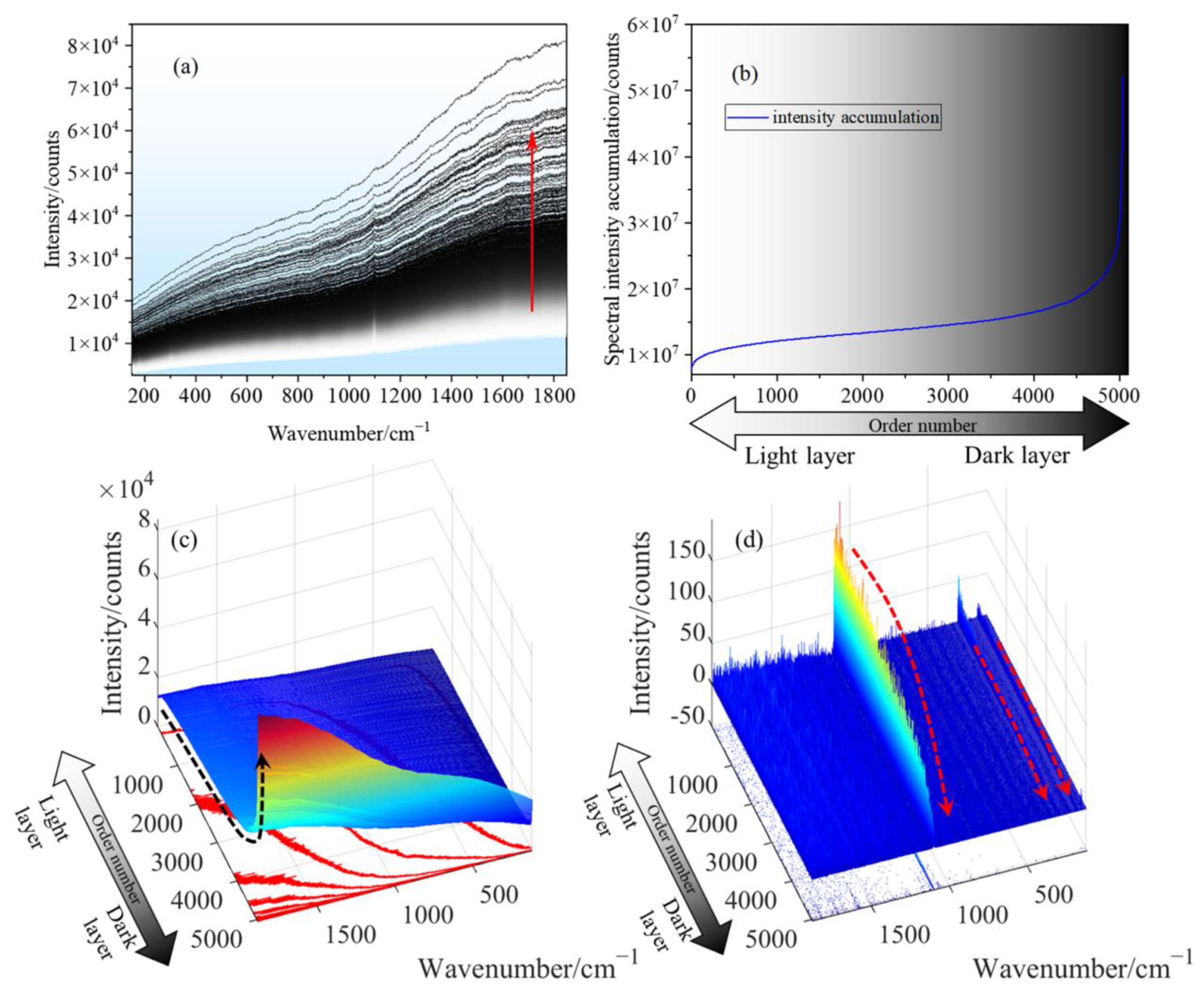
3.1. The Raman Baseline—Fluorescence
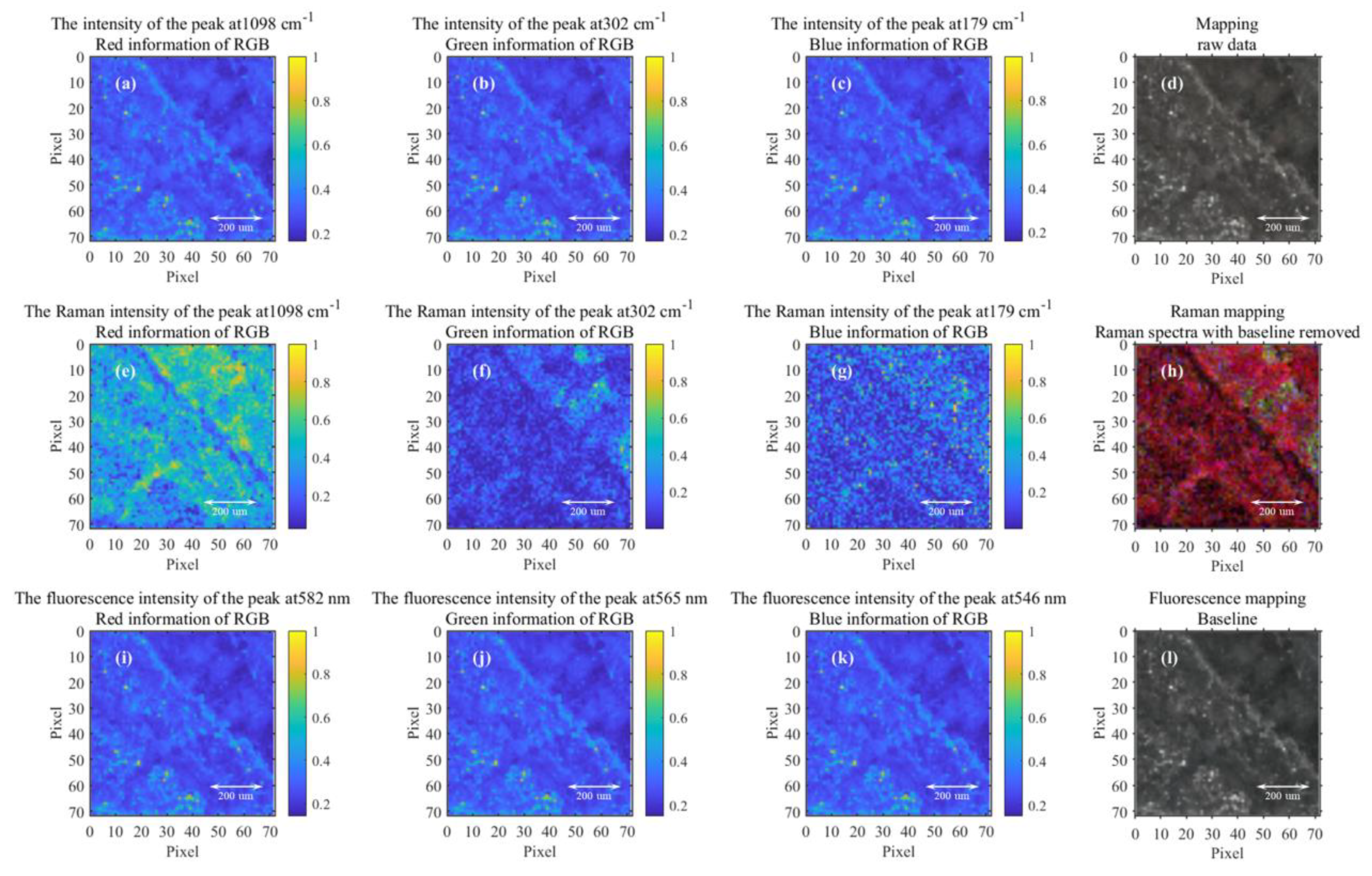
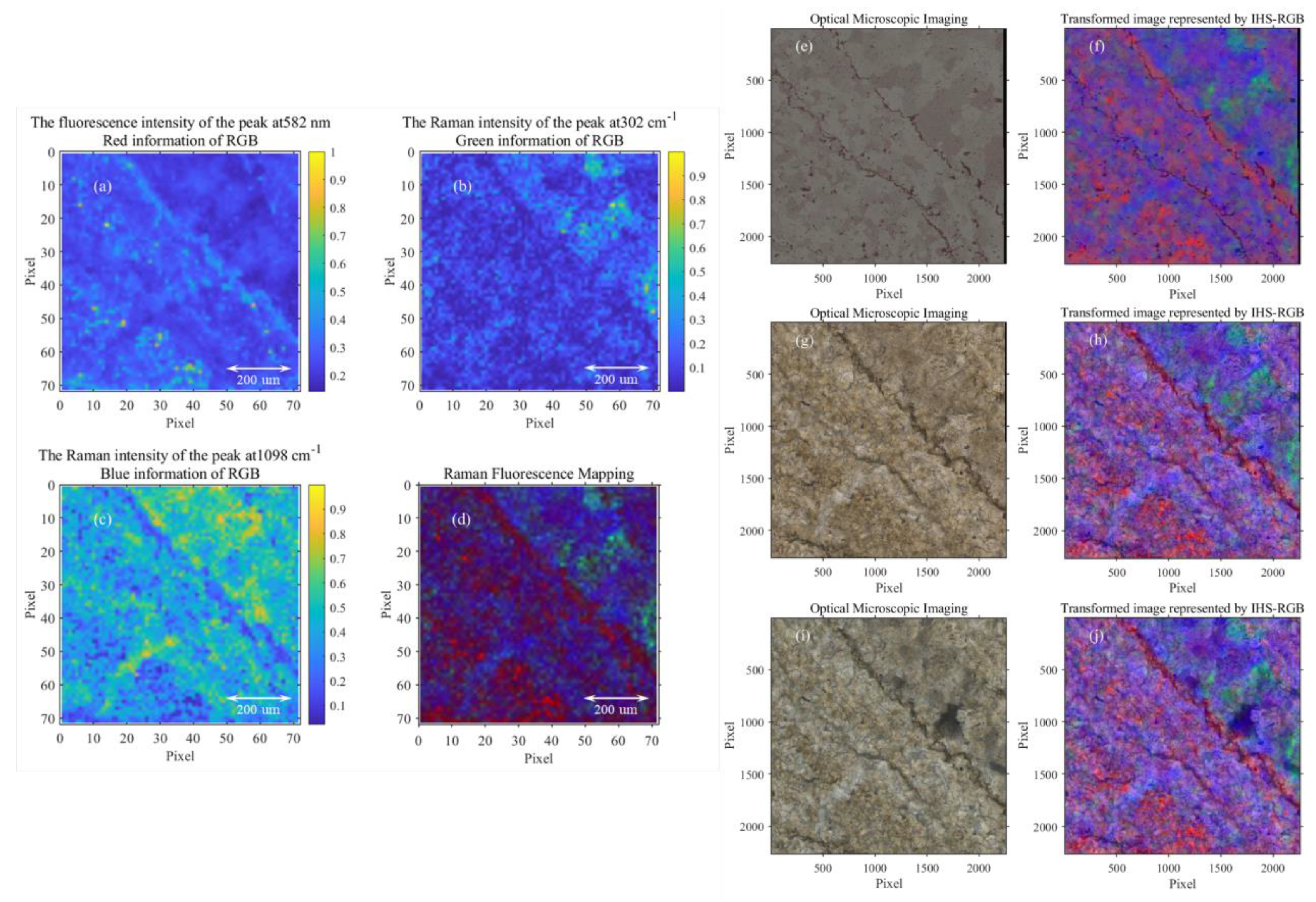
3.2. The Fusion of Microscopic Image and Raman Fluorescence Mapping
4. Discussion
4.1. Astrobiology Significance of Stromatolites
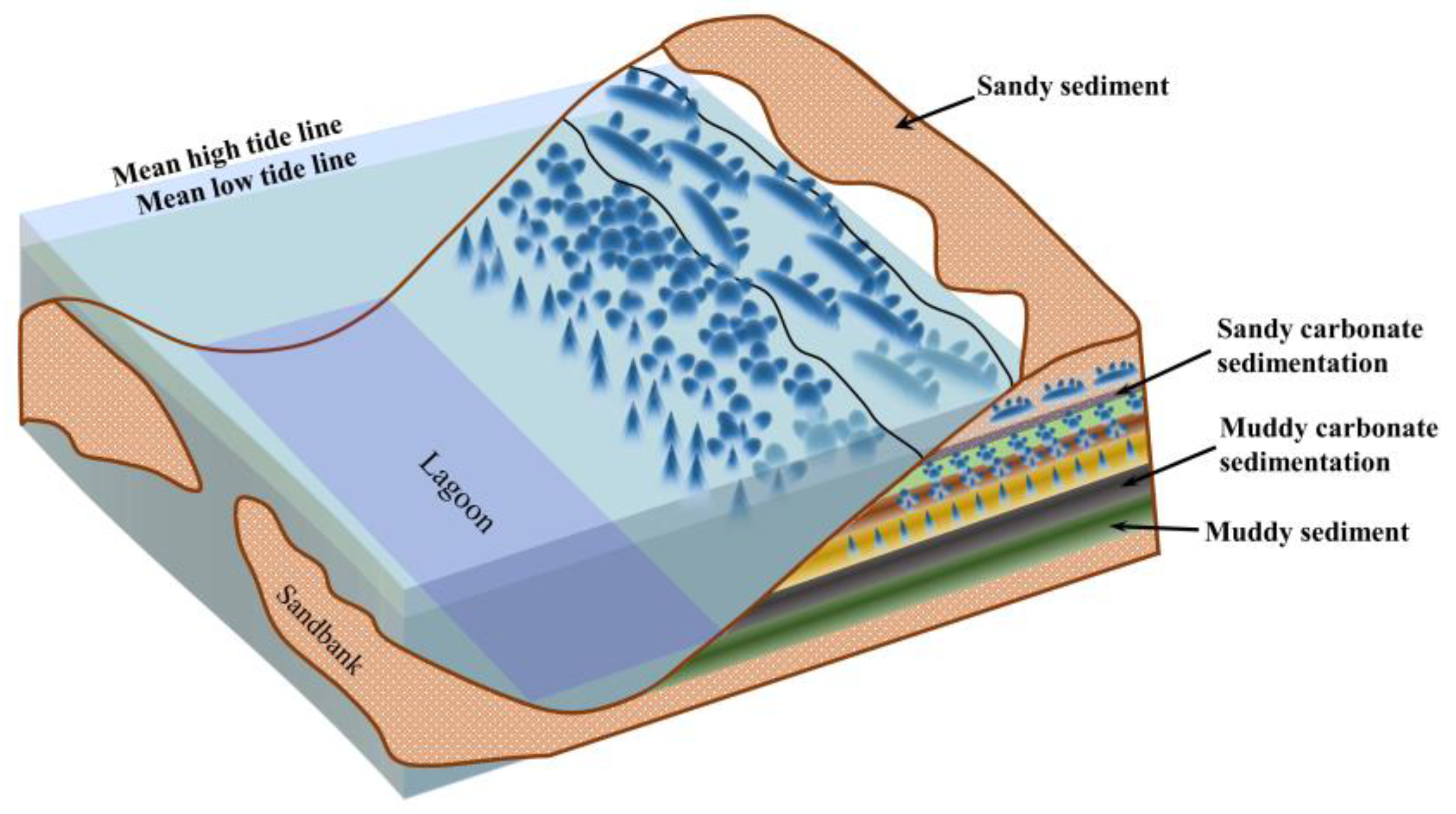
4.2. Relationship between Stromatolites and Sedimentary Facies
4.3. Scientific Research Value of Searching for Stromatolites on Planets
4.4. Potential Applications and Limitations in Other Fields
5. Conclusions
Author Contributions
Funding
Institutional Review Board Statement
Informed Consent Statement
Data Availability Statement
Conflicts of Interest
References
- Gasda, P.J.; Haldeman, E.B.; Wiens, R.C.; Rapin, W.; Bristow, T.F.; Bridges, J.C.; Schwenzer, S.P.; Clark, B.; Herkenhoff, K.; Frydenvang, J.; et al. In situ detection of boron by ChemCam on Mars. Geophys. Res. Lett. 2017, 44, 8739–8748. [Google Scholar] [CrossRef]
- Hollis, J.R.; Abbey, W.; Beegle, L.W.; Bhartia, R.; Ehlmann, B.L.; Miura, J.; Monacelli, B.; Moore, K.; Nordman, A.; Scheller, E.; et al. A deep-ultraviolet raman and fluorescence spectral library of 62 minerals for the sherloc instrument onboard mars 2020. Planet. Space Sci. 2021, 209, 105356. [Google Scholar]
- Anderson, R.B.; Forni, O.; Cousin, A.; Wiens, R.C. Post-landing major element quantification using SuperCam laser induced breakdown spectroscopy. Spectrochim. Acta Part B At. Spectrosc. 2022, 188, 106347. [Google Scholar] [CrossRef]
- Osterhout, J.T.; Schopf, J.W.; Kudryavtsev, A.B.; Czaja, A.D.; Williford, K.H. Deep-UV Raman Spectroscopy of Carbonaceous Precambrian Microfossils: Insights into the Search for Past Life on Mars. Astrobiology 2022, 22, 1239–1254. [Google Scholar] [CrossRef]
- Schopf, J.W.; Kudryavtsev, A.B.; Czaja, A.D.; Tripathi, A.B. Evidence of Archean life: Stromatolites and microfossils. Precambrian Res. 2007, 158, 141–155. [Google Scholar] [CrossRef]
- Schopf, J.W.; Kitajima, K.; Spicuzza, M.J.; Kudryavtsev, A.B.; Valley, J.W. SIMS analyses of the oldest known assemblage of microfossils document their taxon-correlated carbon isotope compositions. Proc. Natl. Acad. Sci. USA 2018, 115, 53–58. [Google Scholar] [CrossRef] [Green Version]
- Nutman, A.; Bennett, V.; Friend, C.; Van Kranendonk, M.J.; Chivas, A.R. Rapid emergence of life shown by discovery of 3700-million-year-old microbial structures. Nature 2016, 537, 535–538. [Google Scholar] [CrossRef] [PubMed] [Green Version]
- Allwood, A.C.; Rosing, M.T.; Flannery, D.T.; Hurowitz, J.A.; Heirwegh, C.M. Reassessing evidence of life in 3700-million-year-old rocks of Greenland. Nature 2018, 563, 241–244. [Google Scholar] [CrossRef]
- Dresselhaus, M.S.; Jorio, A.; Hofmann, M.; Dresselhaus, G.; Saito, R. Raman spectroscopy. Nano Lett. 2010, 10, 751–758. [Google Scholar] [CrossRef]
- Rull, F.; Maurice, S.; Hutchinson, I.; Moral, A.; Perez, C.; Diaz, C.; Colombo, M.; Belenguer, T.; Lopez-Reyes, G.; Sansano, A.; et al. The Raman Laser Spectrometer for the ExoMars Rover Mission to Mars. Astrobiology 2017, 17, 627–654. [Google Scholar] [CrossRef] [Green Version]
- Veneranda, M.; Lopez-Reyes, G.; Manrique, J.; Sanz-Arranz, A.; Medina, J.; Pérez, C.; Quintana, C.; Moral, A.; Rodríguez, J.A.; Zafra, J.; et al. Raman spectroscopy and planetary exploration: Testing the ExoMars/RLS system at the Tabernas Desert (Spain). Microchem. J. 2021, 165, 106149. [Google Scholar] [CrossRef]
- Veneranda, M.; Lopez-Reyes, G.; Saiz, J.; Manrique-Martinez, J.A.; Sanz-Arranz, A.; Medina, J.; Moral, A.; Seoane, L.; Ibarmia, S.; Rull, F. ExoFiT trial at the Atacama Desert (Chile): Raman detection of biomarkers by representative prototypes of the ExoMars/Raman Laser Spectrometer. Sci. Rep. 2021, 11, 1461. [Google Scholar] [CrossRef] [PubMed]
- Murphy, A.E.; Jakubek, R.S.; Steele, A.; Fries, M.D.; Glamoclija, M. Raman spectroscopy provides insight into carbonate rock fabric based on calcite and dolomite crystal orientation. J. Raman Spectrosc. 2021, 52, 1155–1166. [Google Scholar] [CrossRef]
- Ruiz-Galende, P.; Torre-Fdez, I.; Aramendia, J.; Gomez-Nubla, L.; Castro, K.; Arana, G.; de Vallejuelo, S.F.-O.; Maguregui, M.; Medina, J.; Baonza, V.G.; et al. New Raman–visible near-infrared database of inorganic and mineralogical planetary and terrestrial compounds and its implications for Mars: Phyllosilicates. J. Raman Spectrosc. 2020, 51, 1750–1760. [Google Scholar] [CrossRef]
- Liu, C.; Ling, Z.; Zhang, J.; Bi, X.; Xin, Y. Laboratory Raman and VNIR spectroscopic studies of jarosite and other secondary mineral mixtures relevant to Mars. J. Raman Spectrosc. 2020, 51, 1575–1588. [Google Scholar] [CrossRef]
- Abbey, W.J.; Bhartia, R.; Beegle, L.W.; DeFlores, L.; Paez, V.; Sijapati, K.; Sijapati, S.; Williford, K.; Tuite, M.; Hug, W.; et al. Deep UV Raman spectroscopy for planetary exploration: The search for in situ organics. Icarus 2017, 290, 201–214. [Google Scholar] [CrossRef]
- Shkolyar, S.; Eshelman, E.J.; Farmer, J.D.; Hamilton, D.; Daly, M.; Youngbull, C. Detecting kerogen as a biosignature using colocated UV time-gated Raman and fluorescence spectroscopy. Astrobiology 2018, 18, 431–453. [Google Scholar] [CrossRef]
- Bhartia, R.; Beegle, L.W.; DeFlores, L.; Abbey, W.; Hollis, J.R.; Uckert, K.; Monacelli, B.; Edgett, K.S.; Kennedy, M.R.; Sylvia, M.; et al. Perseverance’s Scanning Habitable Environments with Raman and Luminescence for Organics and Chemicals (SHERLOC) investigation. Space Sci. Rev. 2021, 217, 58. [Google Scholar] [CrossRef]
- Ning, X.R.; Selesnick, I.W.; Duval, L. Chromatogram baseline estimation and denoising using sparsity (BEADS), Chemom. Intell. Lab. Syst. 2014, 139, 156–167. [Google Scholar] [CrossRef] [Green Version]
- Wang, H.P.; Fang, P.P.; Yan, X.R.; Zhou, Y.C.; Cheng, Y.L.; Yao, L.F.; Jia, J.J.; He, J.Y.; Wan, X. Study on the Raman spectral characteristics of dynamic and static blood and its application in species identification. J. Photochem. Photobiol. B Biol. 2022, 232, 112478. [Google Scholar] [CrossRef]
- Wang, H.P.; Wan, X. Effect of chlorophyll fluorescence quenching on quantitative analysis of adulteration in extra virgin olive oil, Spectrochim. Acta Mol. Biomol. Spectrosc. 2021, 248, 119183. [Google Scholar]
- Wang, H.P.; Xin, Y.J.; Wan, X. Spectral detection technology of vegetable oil: Spectral analysis of porphyrins and terpenoids, Spectrochim. Acta Mol. Biomol. Spectrosc. 2021, 261, 119965. [Google Scholar] [CrossRef]
- Wang, H.P.; Xin, Y.J.; Ma, H.Z.; Fang, P.P.; Li, C.H.; Wan, X.; He, Z.P.; Jia, J.J.; Ling, Z.C. Rapid detection of Chinese-specific peony seed oil by using confocal Raman spectroscopy and chemometrics. Food Chem. 2021, 362, 130041. [Google Scholar] [CrossRef] [PubMed]
- Gribbon, K.T.; Bailey, D.G. A novel approach to real-time bilinear interpolation. In Proceedings of the 2nd IEEE International Workshop on Electronic Design, Test and Applications (DELTA ‘04), Perth, Australia, 28–30 January 2004; pp. 126–131. [Google Scholar]
- Tu, T.M.; Su, S.C.; Shyu, H.C.; Huang, P.S. A new look at IHS-like image fusion methods. Inf. Fusion 2001, 2, 177–186. [Google Scholar] [CrossRef]
- Rahmani, S.; Strait, M.; Merkurjev, D.; Moeller, M.; Wittman, T. An adaptive IHS pan-sharpening method. IEEE Geosci. Remote Sens. Lett. 2010, 7, 746–750. [Google Scholar] [CrossRef] [Green Version]
- Harris, J.R.; Murray, R.; Hirose, T. IHS transform for the integration of radar imagery with other remotely sensed data. Photogramm. Eng. Remote Sens. 1990, 56, 1631–1641. [Google Scholar]
- Chen, C.M.; Hepner, G.F.; Forster, R.R. Fusion of hyperspectral and radar data using the IHS transformation to enhance urban surface features. ISPRS J. Photogramm. Remote Sens. 2003, 58, 19–30. [Google Scholar] [CrossRef]
- Bonnier, F.; Mehmood, A.; Knief, P.; Meade, A.D.; Hornebeck, W.; Lambkin, H.; Flynn, K.; McDonagh, V.; Healy, C.; Lee, T.C.; et al. In vitro analysis of immersed human tissues by Raman microspectroscopy. J. Raman Spectrosc. 2011, 42, 888–896. [Google Scholar] [CrossRef] [Green Version]
- Yang, H.; Chen, Z.Q. Dominic Papineau, Cyanobacterial spheroids and other biosignatures from microdigitate stromatolites of Mesoproterozoic Wumishan Formation in Jixian, North China. Precambrian Res. 2022, 368, 106496. [Google Scholar] [CrossRef]
- Walter, M.R.; Bauld, J.; Brock, T.D. Chapter 6.2 Microbiology and Morphogenesis of Columnar Stromatolites (Conophyton, Vacerrilla) from Hot Springs in Yellowstone National Park. Dev. Sedimentol. 1976, 20, 273–310. [Google Scholar]
- Zhu, S. Stromatolite; Tianjin University Press: Tianjin, China, 1993; ISBN 7-5618-0404-0. [Google Scholar]
- Vago, J.L.; Westall, F.; Coates, A.J.; Jaumann, R.; Korablev, O.; Ciarletti, V.; Mitrofanov, I.; Josset, J.-L.; De Sanctis, M.C.; Bibringet, J.-P.; et al. Habitability on Early Mars and the Search for Biosignatures with the ExoMars Rover. Astrobiology 2017, 17, 471–510. [Google Scholar] [CrossRef] [PubMed] [Green Version]


Disclaimer/Publisher’s Note: The statements, opinions and data contained in all publications are solely those of the individual author(s) and contributor(s) and not of MDPI and/or the editor(s). MDPI and/or the editor(s) disclaim responsibility for any injury to people or property resulting from any ideas, methods, instructions or products referred to in the content. |
© 2023 by the authors. Licensee MDPI, Basel, Switzerland. This article is an open access article distributed under the terms and conditions of the Creative Commons Attribution (CC BY) license (https://creativecommons.org/licenses/by/4.0/).
Share and Cite
Wang, H.; Yan, X.; Xin, Y.; Fang, P.; Wang, Y.; Liu, S.; Jia, J.; Zhang, L.; Wan, X. Characterization of Stromatolite Organic Sedimentary Structure Based on Spectral Image Fusion. Sensors 2023, 23, 6128. https://doi.org/10.3390/s23136128
Wang H, Yan X, Xin Y, Fang P, Wang Y, Liu S, Jia J, Zhang L, Wan X. Characterization of Stromatolite Organic Sedimentary Structure Based on Spectral Image Fusion. Sensors. 2023; 23(13):6128. https://doi.org/10.3390/s23136128
Chicago/Turabian StyleWang, Hongpeng, Xinru Yan, Yingjian Xin, Peipei Fang, Yian Wang, Sicong Liu, Jianjun Jia, Liang Zhang, and Xiong Wan. 2023. "Characterization of Stromatolite Organic Sedimentary Structure Based on Spectral Image Fusion" Sensors 23, no. 13: 6128. https://doi.org/10.3390/s23136128