

Structural Health Monitoring of Adhesively Bonded Pipe-to-Socket Joints by Integration of Polymer Optical Fibers and Their Load-Dependent Transmission Properties
 , , and
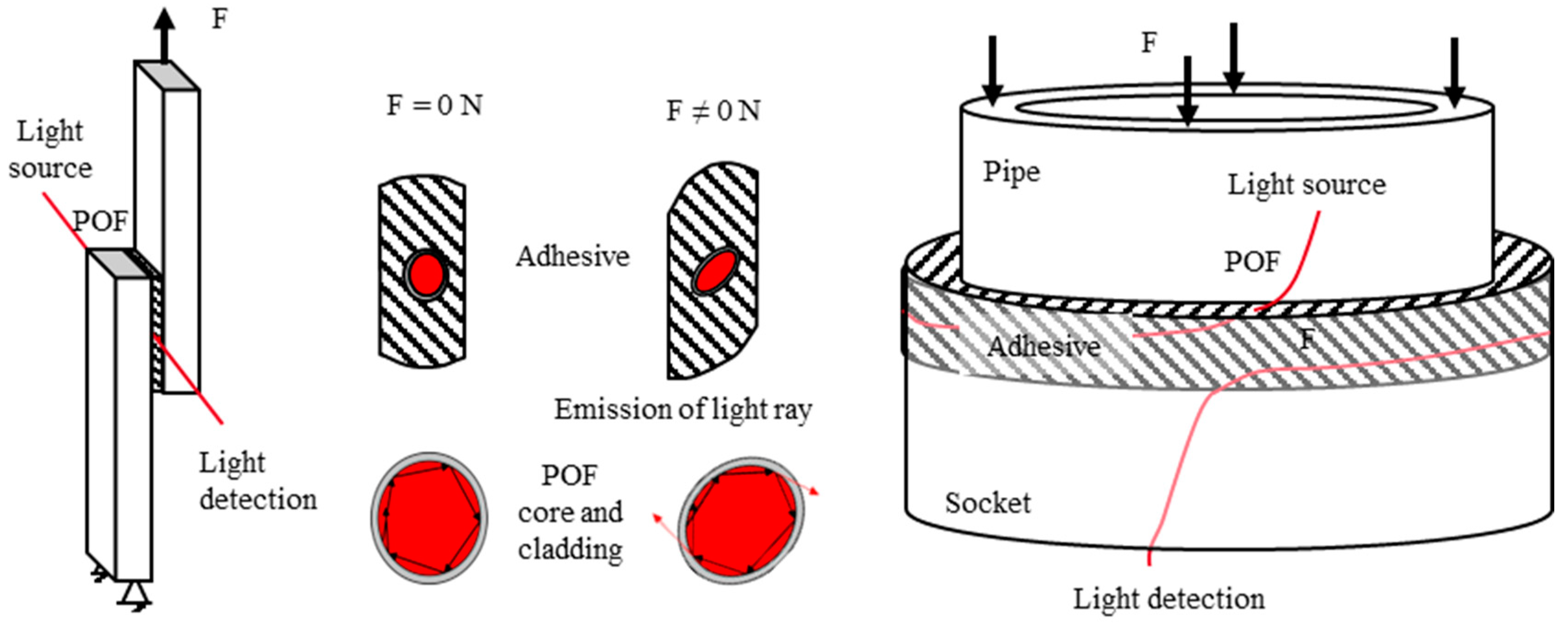
Abstract
:1. Introduction
2. Materials and Methods
2.1. Fundamentals
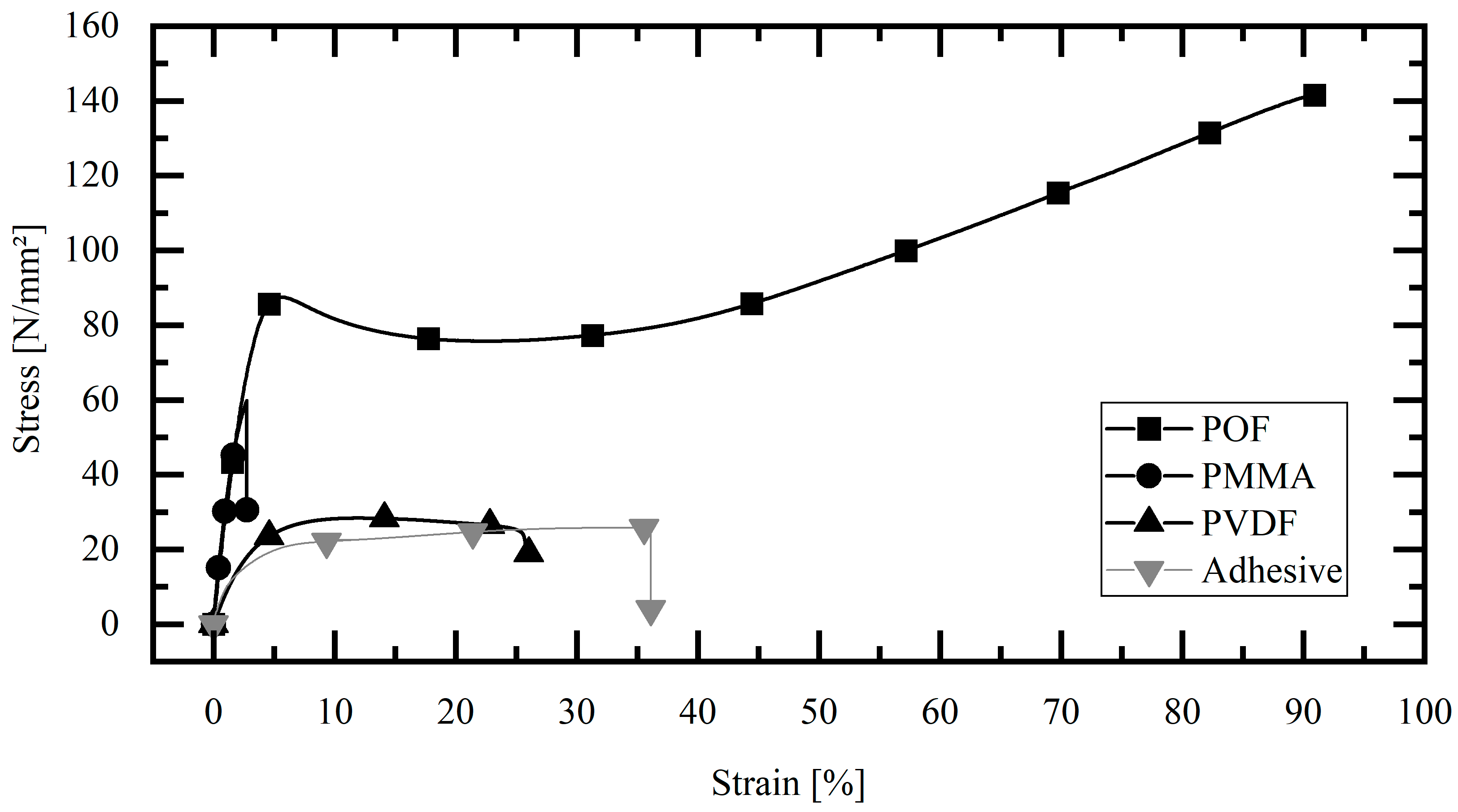
2.2. Polymer Optical Fiber
2.3. Adhesive
2.4. Manufacturing Process
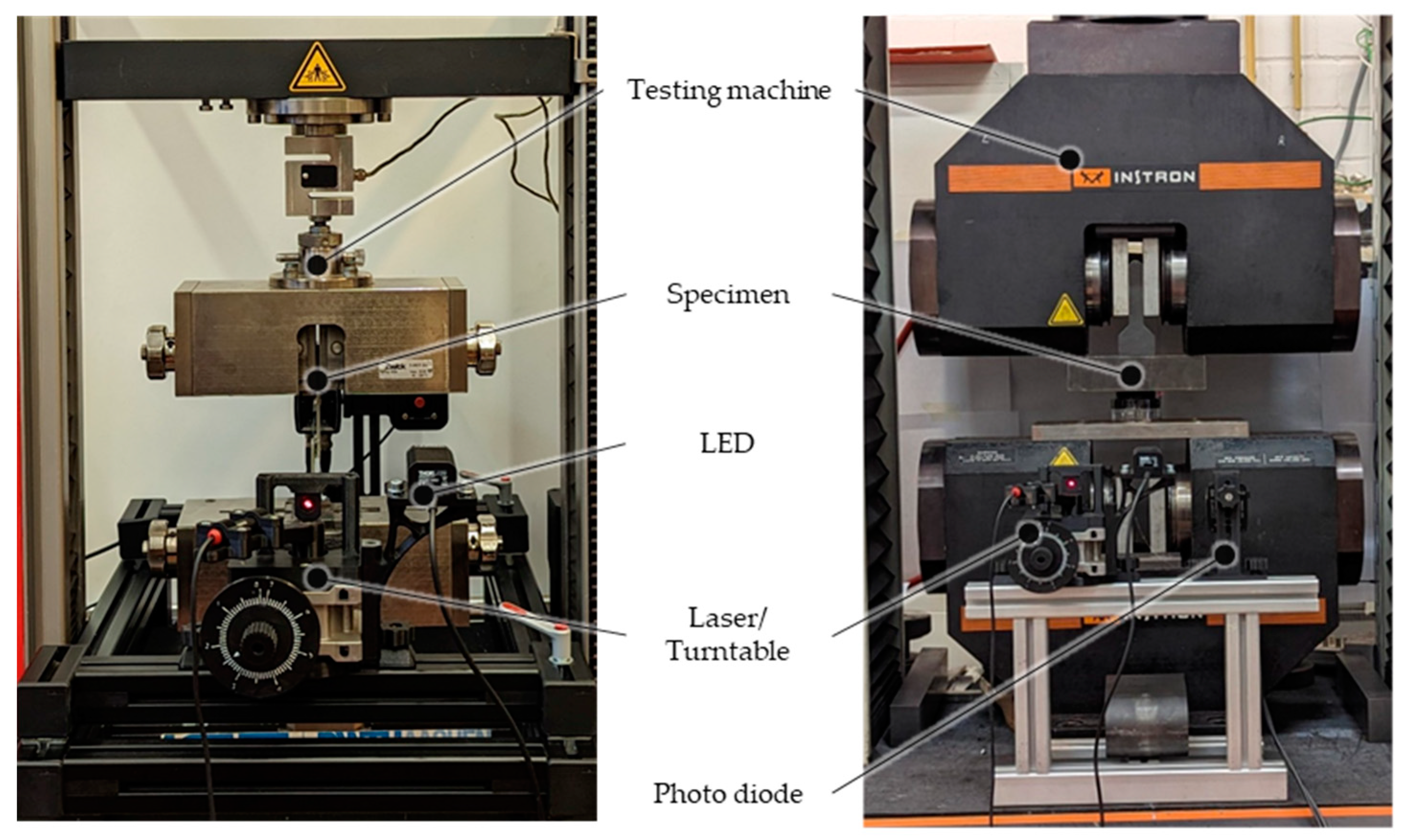
2.5. Optical Test Setup
3. Results
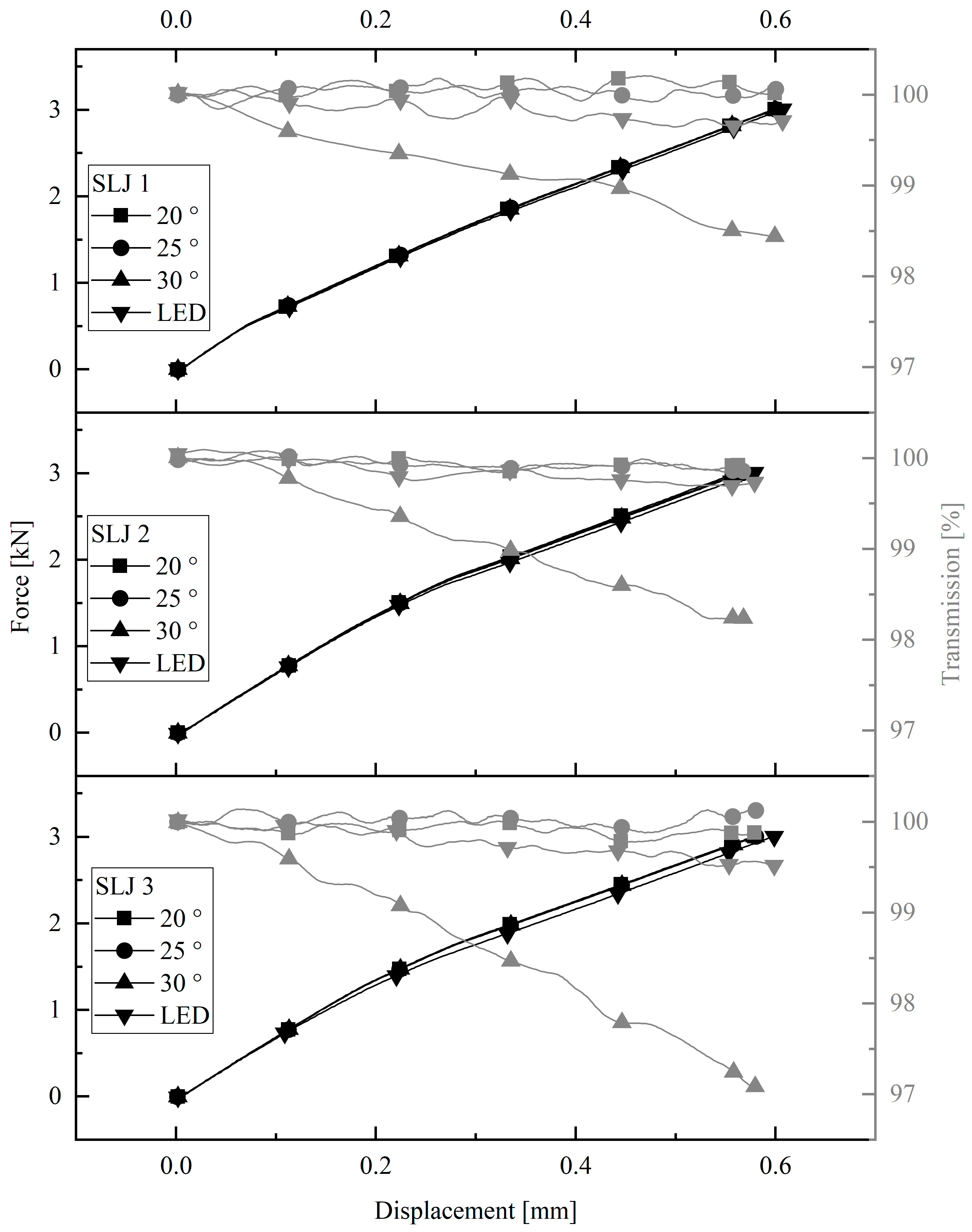
3.1. Single Lap Joint Cyclic Tests
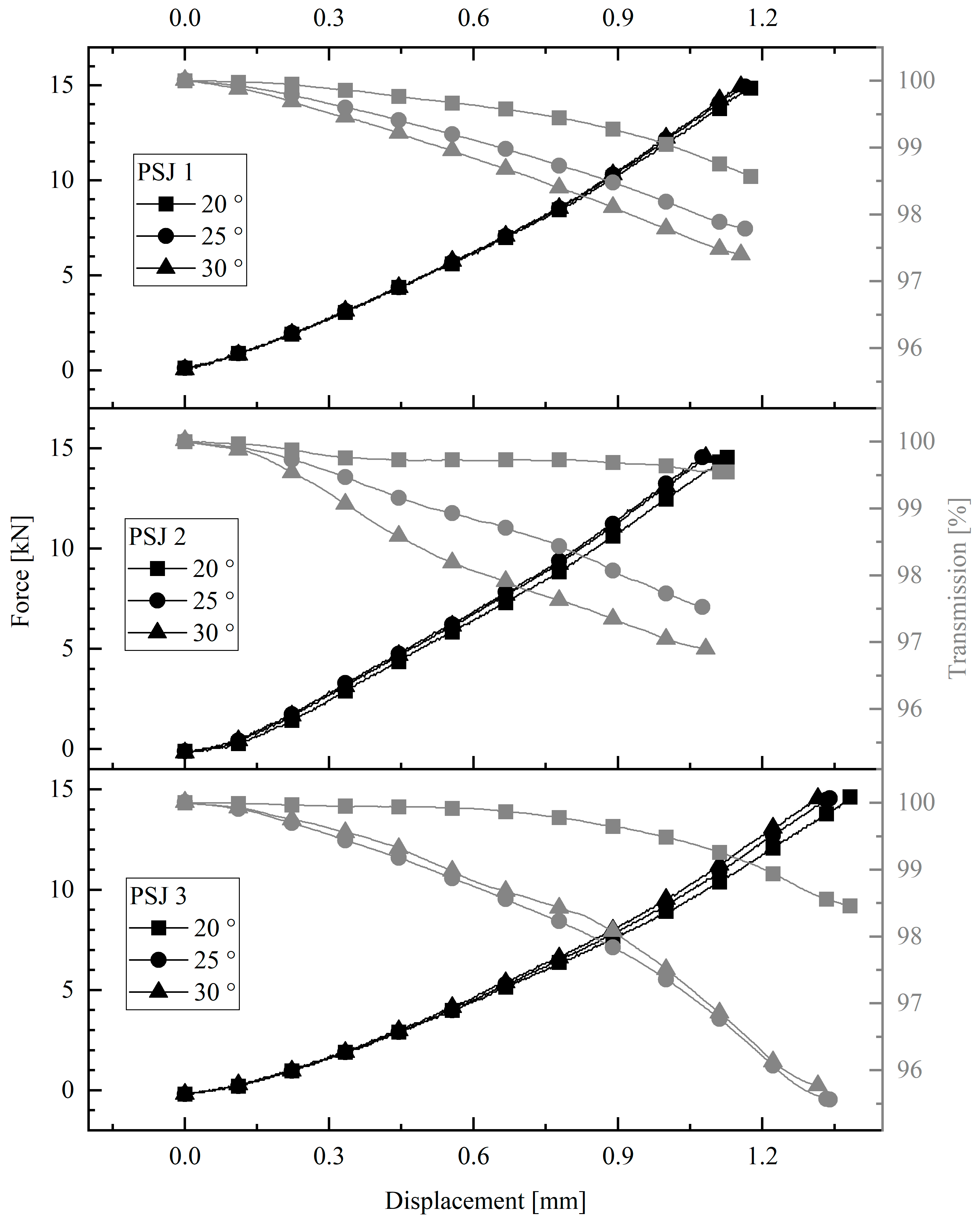
3.2. Pipe-to-Socket Joint Cyclic Tests
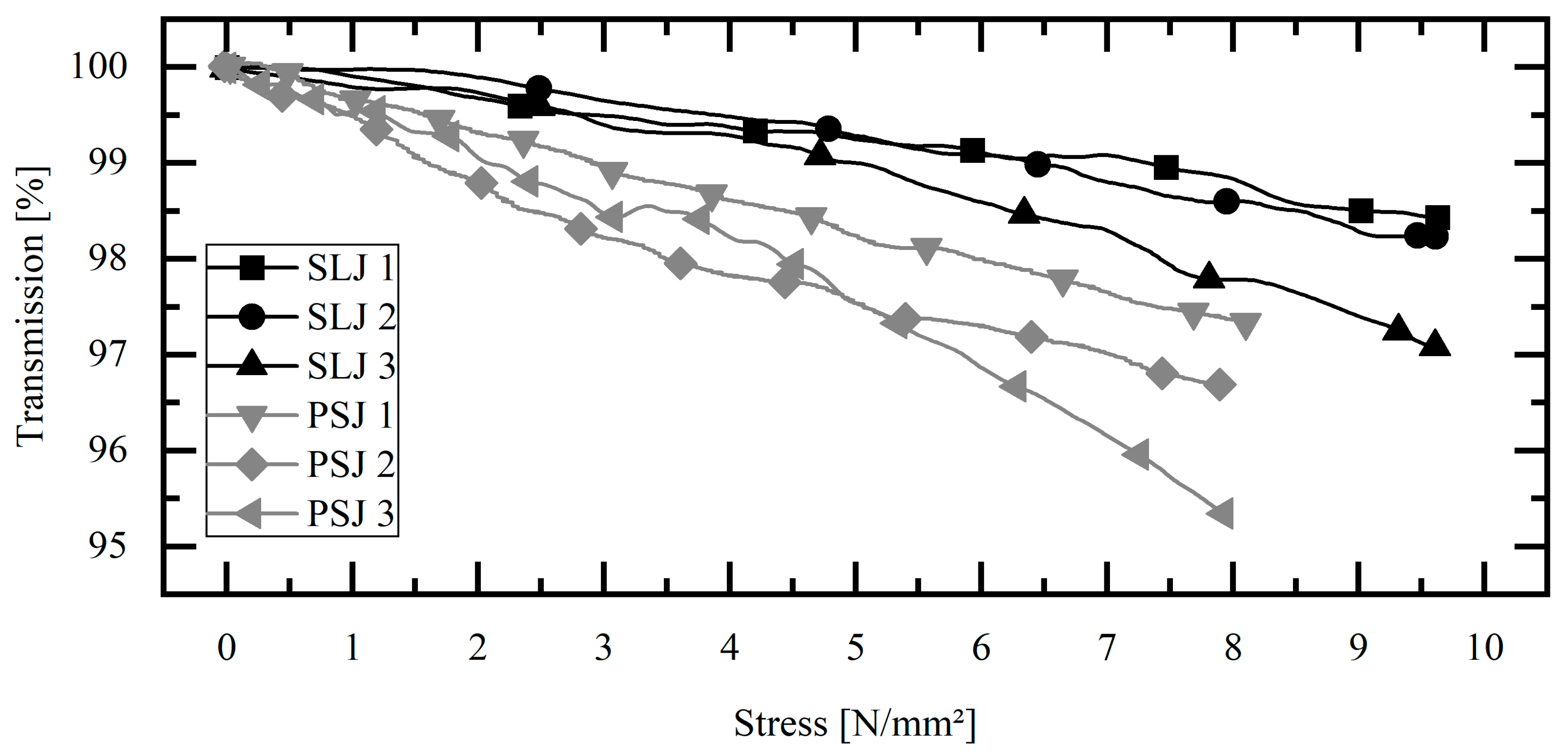
3.3. Comparison of Single-Lap Joint and Pipe-to-Socket Joint
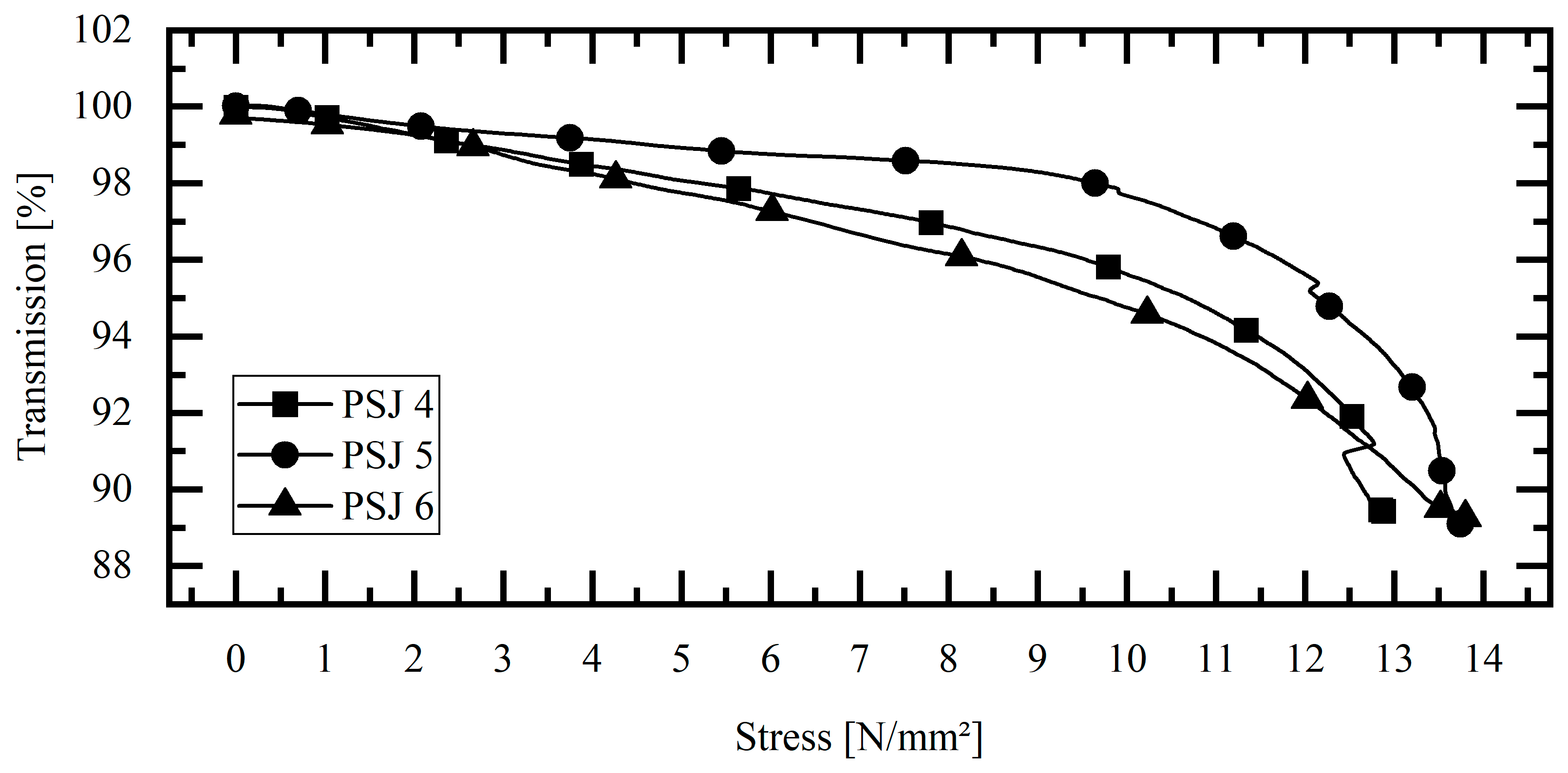
3.4. Pipe-to-Socket Joint, Destructive Tests at Acceptance Angle
4. Discussion
5. Conclusions
Author Contributions
Funding
Institutional Review Board Statement
Informed Consent Statement
Data Availability Statement
Conflicts of Interest
References
- Habenicht, G. Kleben, Grundlagen, Technologien, Anwendungen; Springer: Berlin/Heidelberg, Germany, 2009. [Google Scholar] [CrossRef]
- Cabral, T.D.; Zimmermann, A.C.; Willemann, D.P.; Gonçalves, A.A., Jr. Pipeline Bonded Joints Assembly and Operation Health Monitoring with Embedded FBG Sensors. Eng. Proc. 2020, 2, 5. [Google Scholar] [CrossRef]
- Çitil, Ş.; Ayaz, Y.; Temiz, Ş.; Aydın, M.D. Mechanical behaviour of adhesively repaired pipes subject to internal pressure. Int. J. Adhes. Adhes. 2017, 75, 88–95. [Google Scholar] [CrossRef]
- Albiez, M.; Vallée, T.; Fricke, H.; Ummenhofer, T. Adhesively bonded steel tubes—Part I: Experimental investigations. Int. J. Adhes. Adhes. 2019, 90, 199–210. [Google Scholar] [CrossRef]
- Albiez, M.; Vallée, T.; Ummenhofer, T. Adhesively bonded steel tubes—Part II: Numerical modelling and strength prediction. Int. J. Adhes. Adhes. 2019, 90, 211–224. [Google Scholar] [CrossRef]
- Albiez, M.; Damm, J.; Ummenhofer, T.; Ehard, H.; Schuler, C.; Kaufmann, M.; Vallée, T.; Myslicki, S. Hybrid joining of jacket structures for offshore wind turbines—Validation under static and dynamic loading at medium and large scale. Eng. Struct. 2022, 252, 595. [Google Scholar] [CrossRef]
- Rzadkowski, W.; Tracz, J.; Cisowski, A.; Gardyjas, K.; Groen, H.; Palka, M.; Kowalik, M. Evaluation of Bonding Gap Control Methods for an Epoxy Adhesive Joint of Carbon Fiber Tubes and Aluminum Alloy Inserts. Materials 2021, 14, 1977. [Google Scholar] [CrossRef] [PubMed]
- Kralovec, C.; Lehner, B.; Kirchmayr, M.; Schagerl, M. Sandwich Face Layer Debonding Detection and Size Estimation by Machine-Learning-Based Evaluation of Electromechanical Impedance Measurements. Sensors 2023, 23, 2910. [Google Scholar] [CrossRef] [PubMed]
- Weiland, J.; Hesser, D.; Xiong, W.; Schiebahn, A.; Markert, B.; Reisgen, U. Structural health monitoring of an adhesively bonded CFRP aircraft fuselage by ultrasonic Lamb Waves. Proc. Inst. Mech. Eng. Part G J. Aerosp. Eng. 2020, 234, 2000–2010. [Google Scholar] [CrossRef]
- Sadeghi, M.Z.; Weiland, J.; Preisler, A.; Zimmermann, J.; Schiebahn, A.; Reisgen, U.; Schroeder, K.U. Damage detection in adhesively bonded single lap joints by using backface strain: Proposing a new position for backface strain gauges. Int. J. Adhes. Adhes. 2020, 97, 494. [Google Scholar] [CrossRef]
- Weiland, J.; Sadeghi, M.Z.; Thomalla, J.V.; Schiebahn, A.; Schroeder, K.U.; Reisgen, U. Analysis of back-face strain measurement for adhesively bonded single lap joints using strain gauge, Digital Image Correlation and finite element method. Int. J. Adhes. Adhes. 2020, 97, 491. [Google Scholar] [CrossRef]
- Weiland, J.; Luber, M.; Seewald, R.; Schiebahn, A.; Engelbrecht, R.; Reisgen, U. Structural health monitoring of adhesively bonded joints: Proposing a new method by use of polymer optical fibers. Procedia Struct. Integr. 2020, 28, 1249–1257. [Google Scholar] [CrossRef]
- Weiland, J.; Bartholomee, W.; Luber, M.; Schiebahn, A.; Engelbrecht, R.; Reisgen, U. Investigation into the mechanical behavior of a polymer optical fiber embedded in a structural adhesive. Int. J. Adhes. Adhes. 2022, 117, 18. [Google Scholar] [CrossRef]
- Engelbrecht, R.; Rostan, K.; Weiland, J.; Luber, M.; Schiebahn, A.; Reisgen, U. Modal Distribution in Polymer Optical Fibers as Sensor for Load Monitoring in Semi-Structural Adhesive Bonds. In Proceedings of the 27th International Conference on Optical Fiber Sensors, Technical Digest Series, Alexandria, VI, USA, 29 August–2 September 2022; p. W2.3. [Google Scholar] [CrossRef]
- Weiland, J.; Luber, M.; Rostan, K.; Schiebahn, A.; Engelbrecht, R.; Reisgen, U. Strain Monitoring of a Structural Adhesive Bond by Embedding a Polymer Optical Fiber. In European Workshop on Structural Health Monitoring. EWSHM 2022; Lecture Notes in Civil Engineering; Rizzo, P., Milazzo, A., Eds.; Springer: Cham, Switzerland, 2022; Volume 253. [Google Scholar] [CrossRef]
- Grundmann, N. Einfluss der Einbettung von FBGs in Strukturelle CFK-Filmklebstoffklebungen auf die Eigenschaften von Klebung und Sensor. Ph.D. Thesis, IFAM Bremen, Bremen, Germany, 2021. [Google Scholar] [CrossRef]
- Fevery, S. Advanced Monitoring of Structural Adhesive Joints During Ageing Tests through Embedded Sensors. Master’s Thesis, KU Leuven, Leuven, Belgium, 2021. [Google Scholar]
- Hildebrand, J.; Kuhne, M. Vorrichtung und Verfahren zur Überwachung des Zustandes einer Klebeverbindung. DE Patent 102011084579B4, 2013. [Google Scholar]
- Hildebrand, J.; Könke, C. Monitoring von Klebverbindungen mittels faseroptischen Messsystem—MOFAS. Schlussber. IGF Vorh. 2015, 2015, 17777. [Google Scholar]
- Shin, C.S.; Yang, Y.J.U.; Liaw, S.K. Monitoring fatigue damage of an adhesive joint using fiber optics sensors. In Proceedings of the 11th International Conference on Damage Assessment of Structures (Damas 2015). Ghent, Belgium, 24–26 August 2015; Volume 843, p. 12032. [Google Scholar]
- Shin, C.-S.U.; Lin, T.-C. Adhesive Joint Integrity Monitoring Using the Full Spectral Response of Fiber Bragg Grating Sensors. Polymers 2021, 13, 17. [Google Scholar] [CrossRef] [PubMed]
- Shin, C.-S.U.; Lin, T.-C. Hygrothermal Damage Monitoring of Composite Adhesive Joint Using the Full Spectral Response of Fiber Bragg Grating Sensors. Polymers 2022, 14, 3. [Google Scholar] [CrossRef] [PubMed]
- Schulz, W.L.; Udd, E.; Morrell, M.; Seim, J.M.; Perez, I.M.U.; Trego, A. Health monitoring of an adhesive joint using a multiaxis fiber grating strain sensor system. In Proceedings of the Nondestructive Evaluation of Aging Aircraft, Airports, and Aerospace Hardware III, Newport Beach, CA, USA, 28 January 1999. [Google Scholar]
- Claunch, E.; Seyam, A.-F.U.; Peters, K. Smart Composite Using Optic Fiber Sensor Embedded in Three Dimensional Woven Preform. SAMPE 2019—Charlotte, NC, USA. SAMPE 04112019. Available online: https://digitallibrarynasampe.org/data/webpages/s2019_webpages/227-TP19--1436.html (accessed on 15 March 2023).
- Hamouda, T.; Seyam, A.-F.M.U.; Peters, K. Evaluation of the integrity of 3D orthogonal woven composites with embedded polymer optical fibers. Compos. Part B Eng. 2015, 78, 79–85. [Google Scholar] [CrossRef]
- Hamouda, T.; Abdel-Fattah, M.; Seyam, U.; Peters, K. 2B4_0258_ The Em-Bedded Polymeric Optical Fiber (Pof). In 3D Composite for Health Monitoring, Proceedings of the 19th World Textile Conference, Ghent, Belgium, 20–22 October 2019; Autex: Lodz, Poland, 2019. [Google Scholar]
- Claunch, E.-L.C. Smart Composites: Optical Sensors Embedded in 3D Orthogonal Woven Fabric for Structural Health Monitoring Applications. Ph.D. Thesis, North Carolina State University, Raleigh, NC, USA, 2019. [Google Scholar]
- Ziemann, O.; Krauser, J.; Zamzow, P.E.; Daum, W. POF-Handbuch Optische Kurzstrecken-Übertragungssysteme; Springer: Berlin/Heidelberg, Germany, 2007. [Google Scholar] [CrossRef]
- Kuang, K.S.C.; Cantwell, W.J.; Scully, P.J. An evaluation of a novel plastic optical fibre sensor for axial strain and bend measurements. Meas. Sci. Technol. 2002, 13, 303. [Google Scholar] [CrossRef]


Disclaimer/Publisher’s Note: The statements, opinions and data contained in all publications are solely those of the individual author(s) and contributor(s) and not of MDPI and/or the editor(s). MDPI and/or the editor(s) disclaim responsibility for any injury to people or property resulting from any ideas, methods, instructions or products referred to in the content. |
© 2023 by the authors. Licensee MDPI, Basel, Switzerland. This article is an open access article distributed under the terms and conditions of the Creative Commons Attribution (CC BY) license (https://creativecommons.org/licenses/by/4.0/).
Share and Cite
Weiland, J.; Kunze, B.; Luber, M.; Krüger, N.; Schiebahn, A.; Engelbrecht, R.; Reisgen, U. Structural Health Monitoring of Adhesively Bonded Pipe-to-Socket Joints by Integration of Polymer Optical Fibers and Their Load-Dependent Transmission Properties. Sensors 2023, 23, 4748. https://doi.org/10.3390/s23104748
Weiland J, Kunze B, Luber M, Krüger N, Schiebahn A, Engelbrecht R, Reisgen U. Structural Health Monitoring of Adhesively Bonded Pipe-to-Socket Joints by Integration of Polymer Optical Fibers and Their Load-Dependent Transmission Properties. Sensors. 2023; 23(10):4748. https://doi.org/10.3390/s23104748
Chicago/Turabian StyleWeiland, Josef, Billy Kunze, Michael Luber, Naomi Krüger, Alexander Schiebahn, Rainer Engelbrecht, and Uwe Reisgen. 2023. "Structural Health Monitoring of Adhesively Bonded Pipe-to-Socket Joints by Integration of Polymer Optical Fibers and Their Load-Dependent Transmission Properties" Sensors 23, no. 10: 4748. https://doi.org/10.3390/s23104748