
Visual Servoed Autonomous Landing of an UAV on a Catamaran in a Marine Environment


Abstract
:1. Introduction
1.1. Related Work
1.2. Contributions
- A new software architecture powered by the ROS2 middleware and designed specifically to be modular for both simulation tests and outdoor tests in a real marine environment;
- Design and implementation of an improved landing state machine, with the addition of a new state and the introduction of a new procedure to synchronize the position of the quadrotor with the catamaran before the landing approach;
- Simulations in a software-in-the-loop environment of a safe landing on a landing platform, whose movements were replicated from the telemetry of the catamaran recorded during outdoor tests in a marine environment;
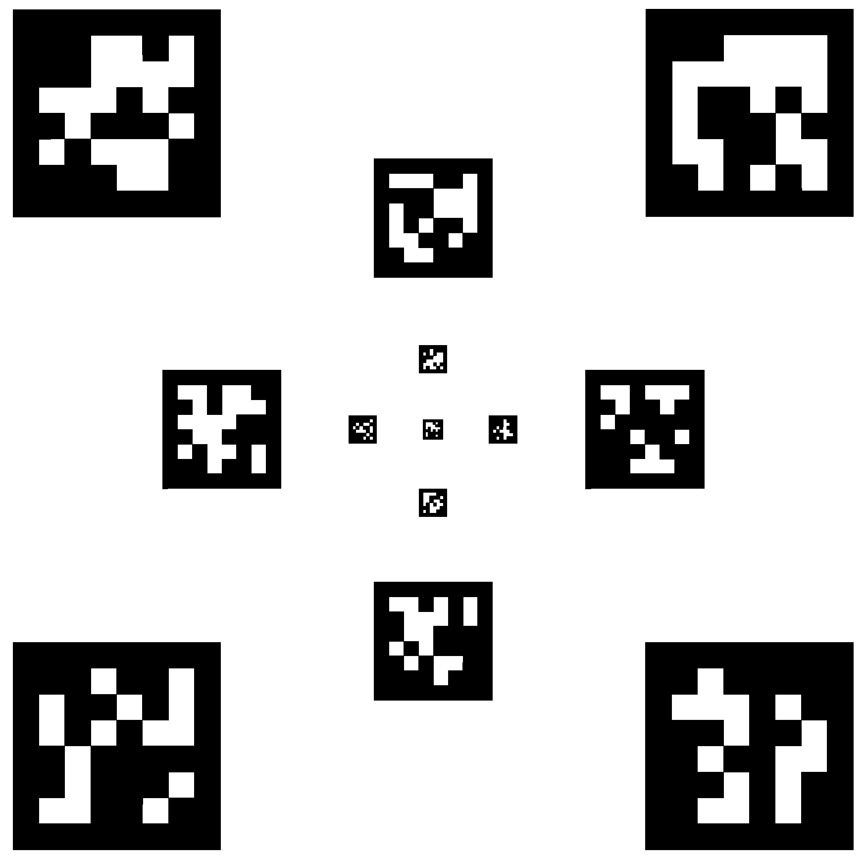
- Realization and integration on the catamaran of a new landing platform, with more tags to gain better robustness during the landing procedure;
- Validation of the vision system using the recordings of a manual landing on the catamaran in a marine environment.
2. System Overview
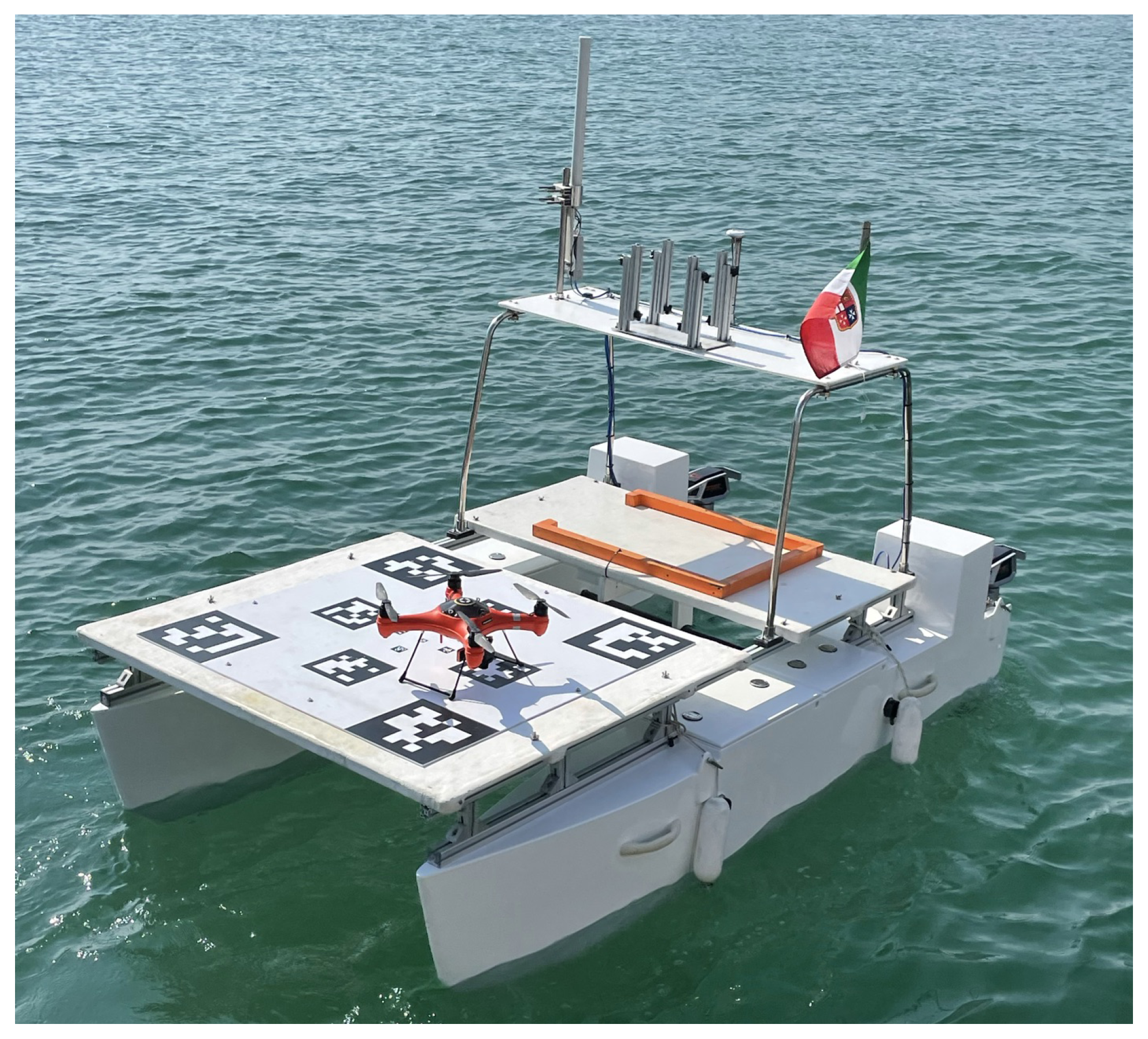
2.1. Catamaran
2.2. Quadrotor
3. Methodology
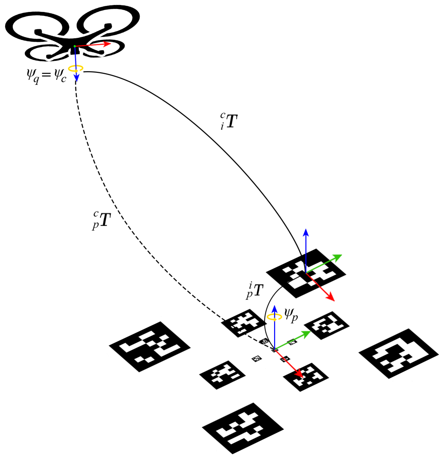
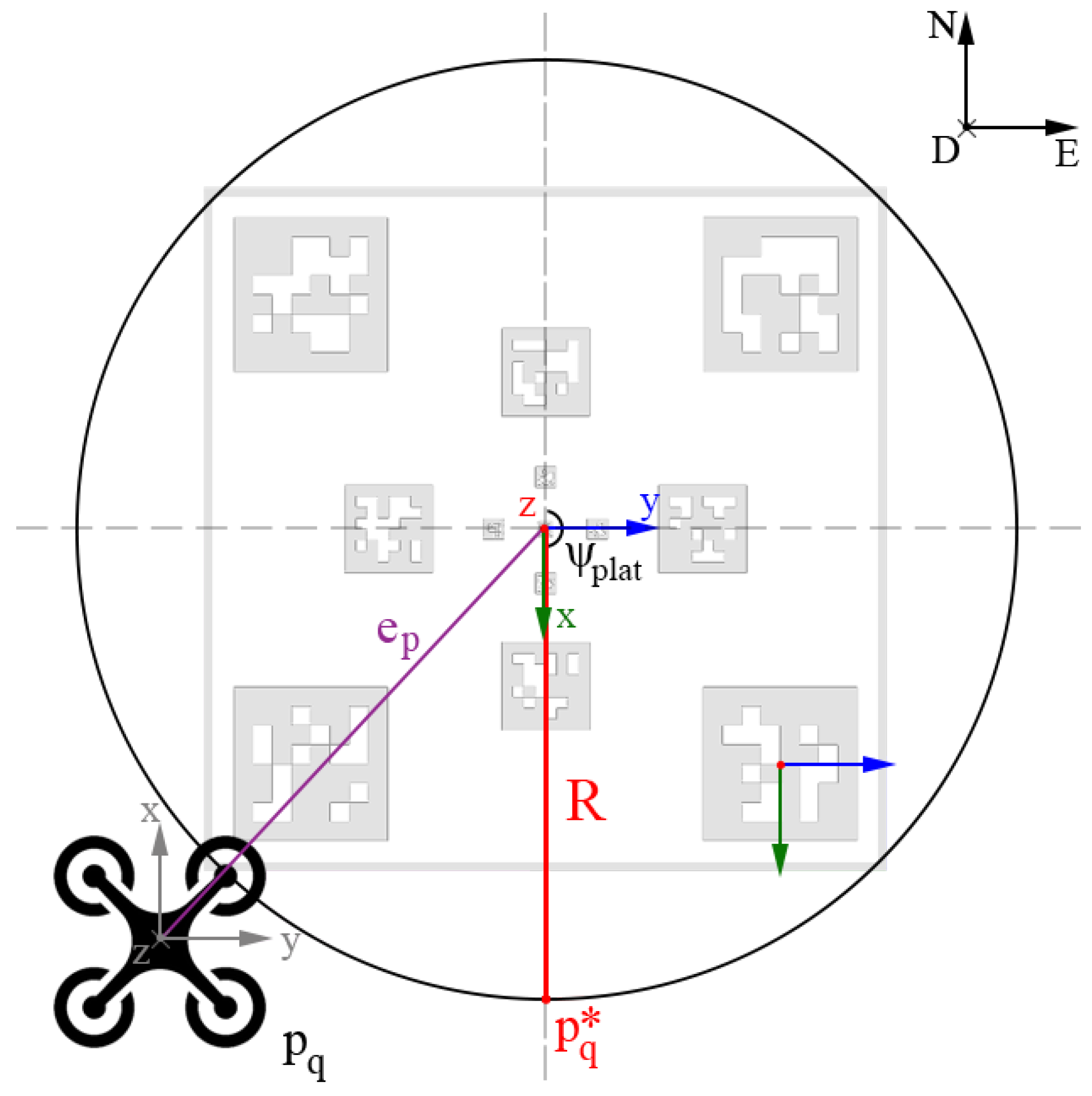
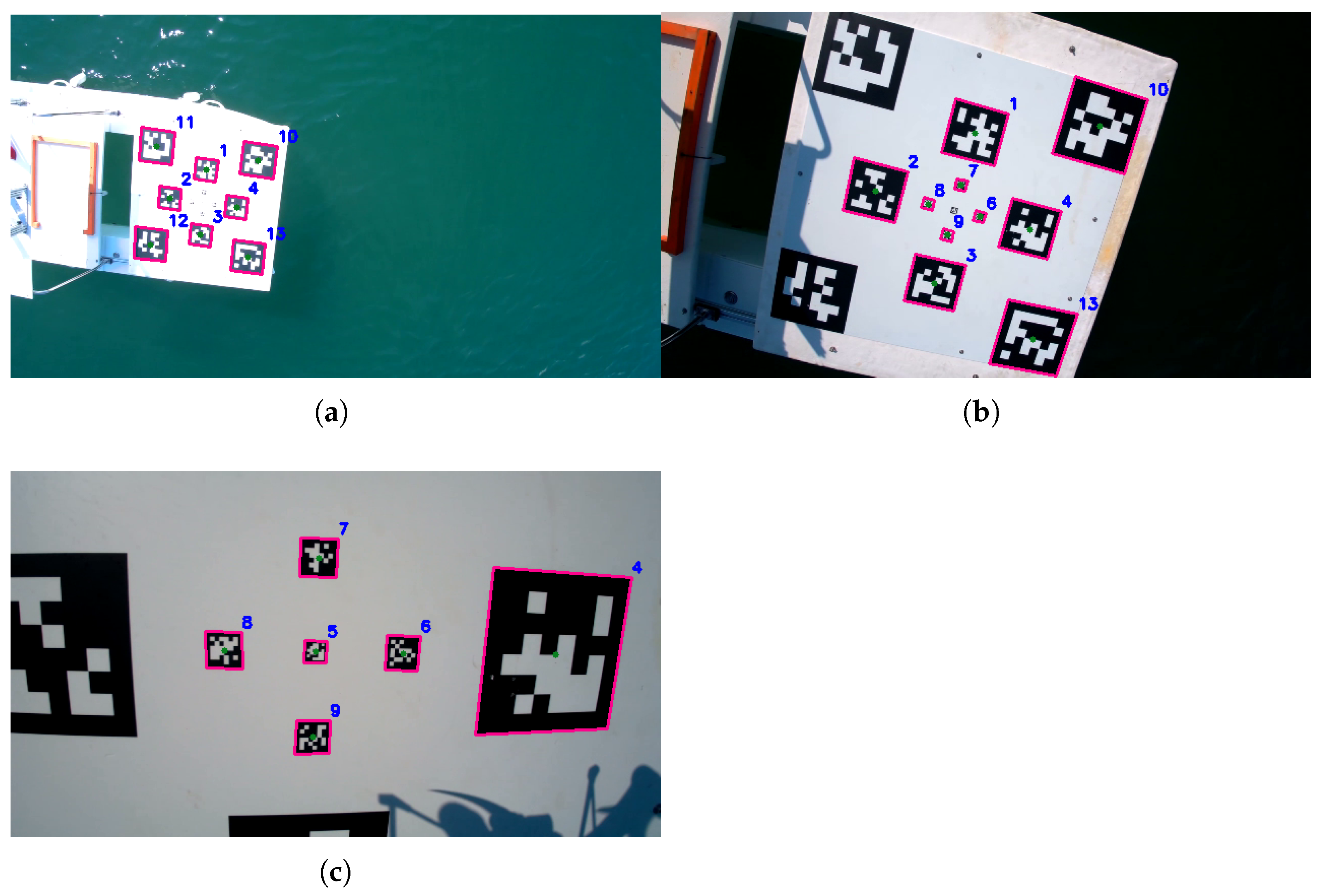
3.1. Perception and Pose Estimation
3.2. Horizontal Platform Tracking
3.3. Vertical Platform Compensation
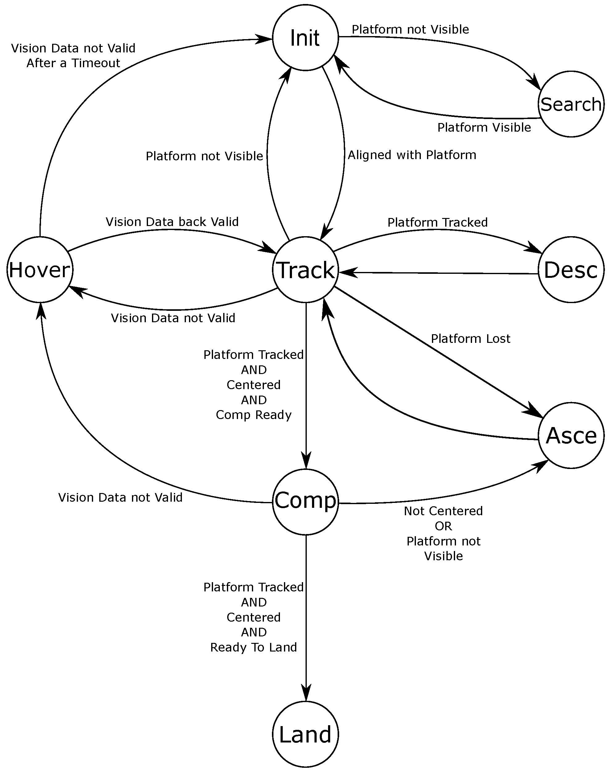
3.4. Finite State Machine
3.4.1. Initialization
3.4.2. Searching
3.4.3. Tracking
3.4.4. Hovering
3.4.5. Descending
3.4.6. Ascending
3.4.7. Compensation
3.4.8. Landing
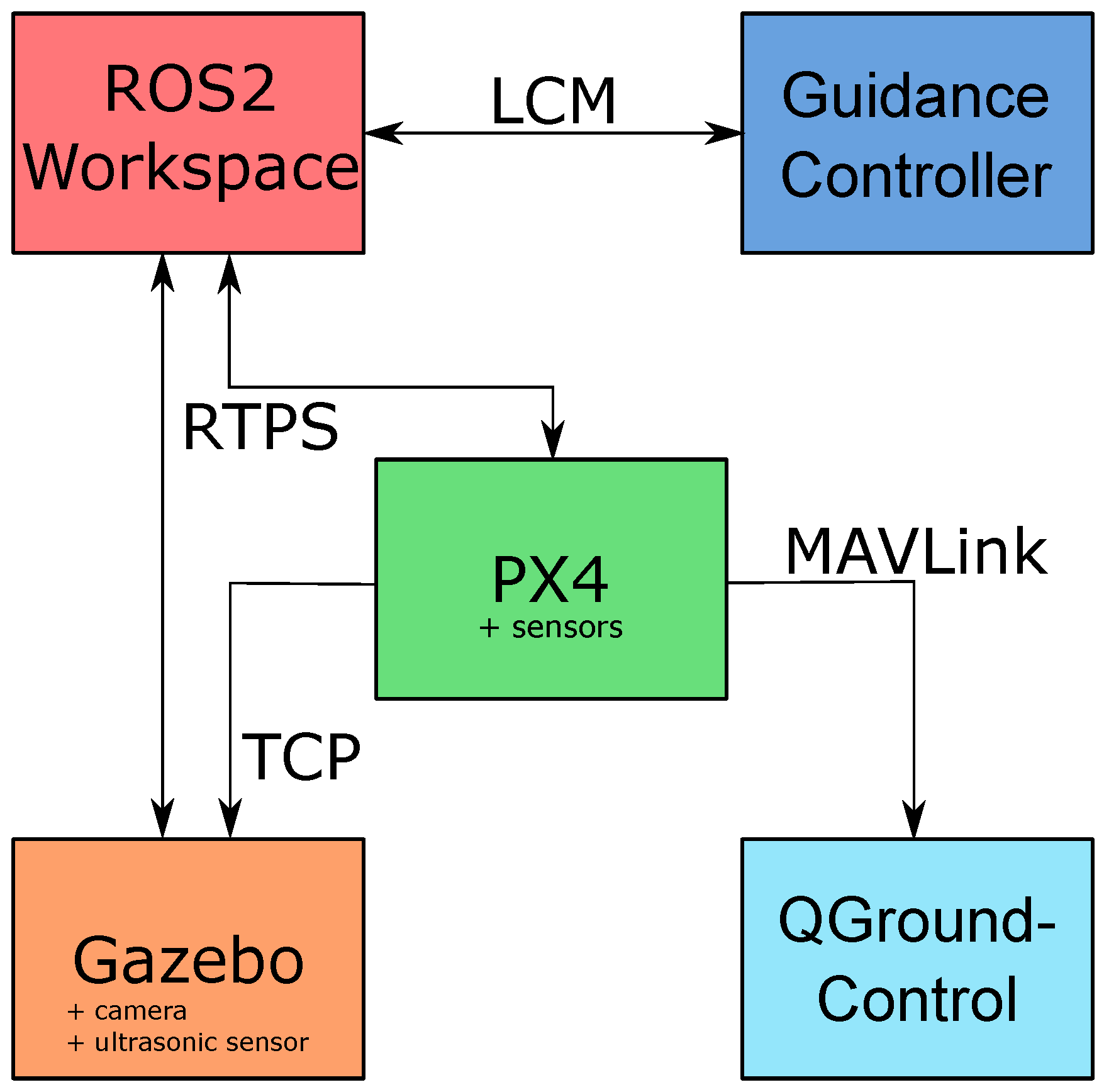
4. Software Architecture
4.1. Gazebo
4.2. PX4
4.3. ROS2
4.4. Guidance Controller
4.5. QGroundControl
4.6. RTPS
5. Emulation Results
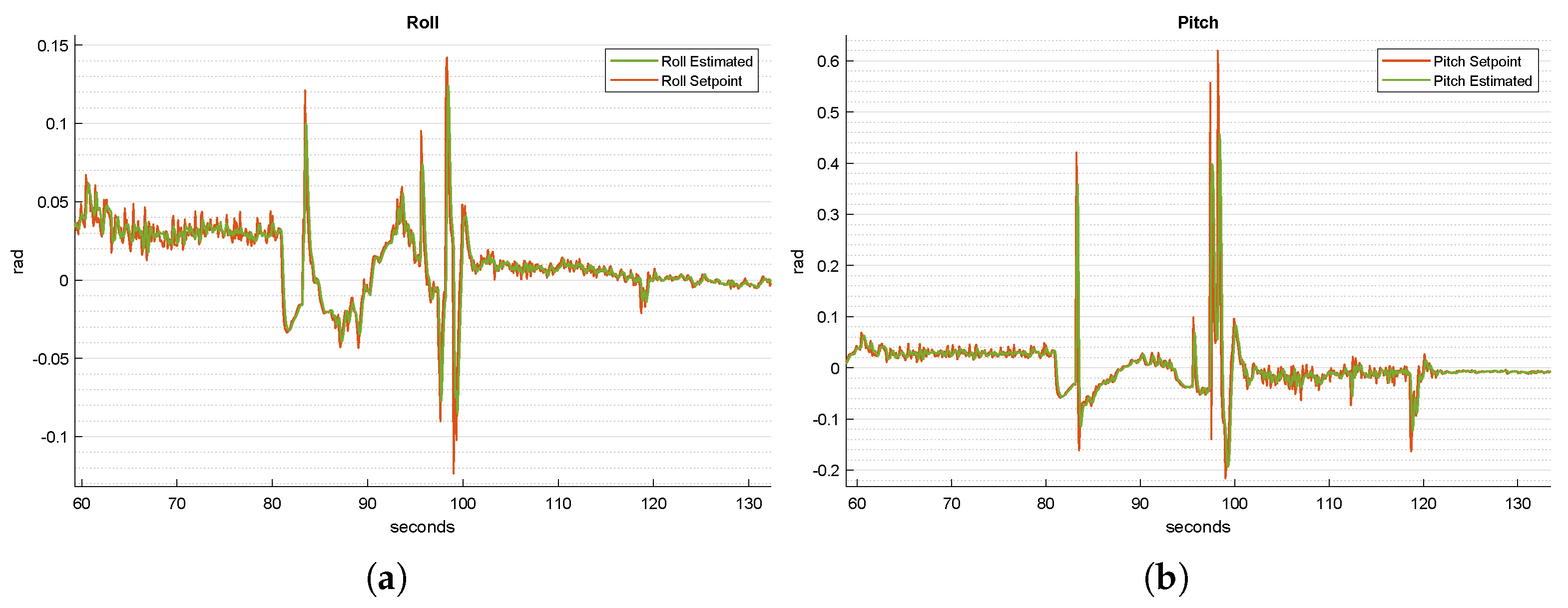
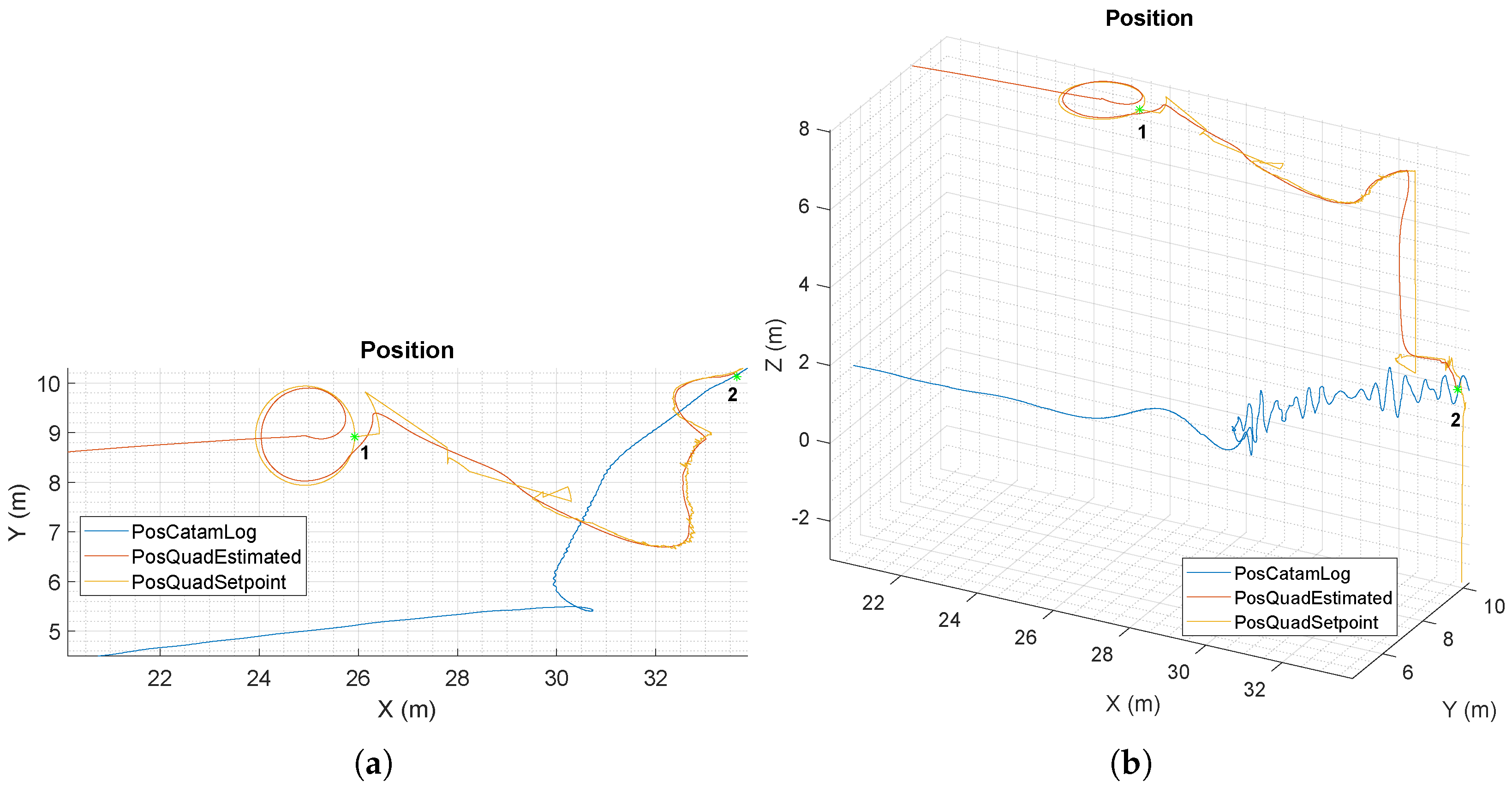
5.1. Software-in-the-Loop Simulation
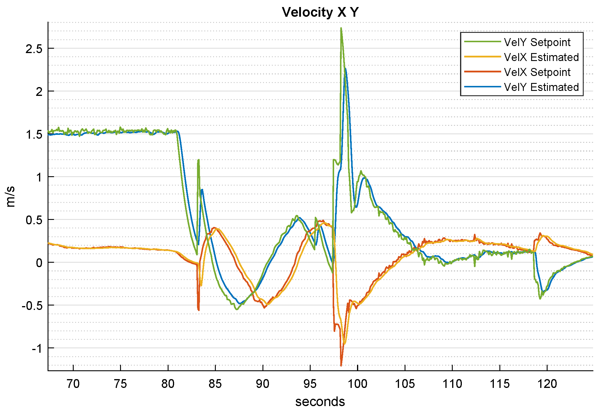
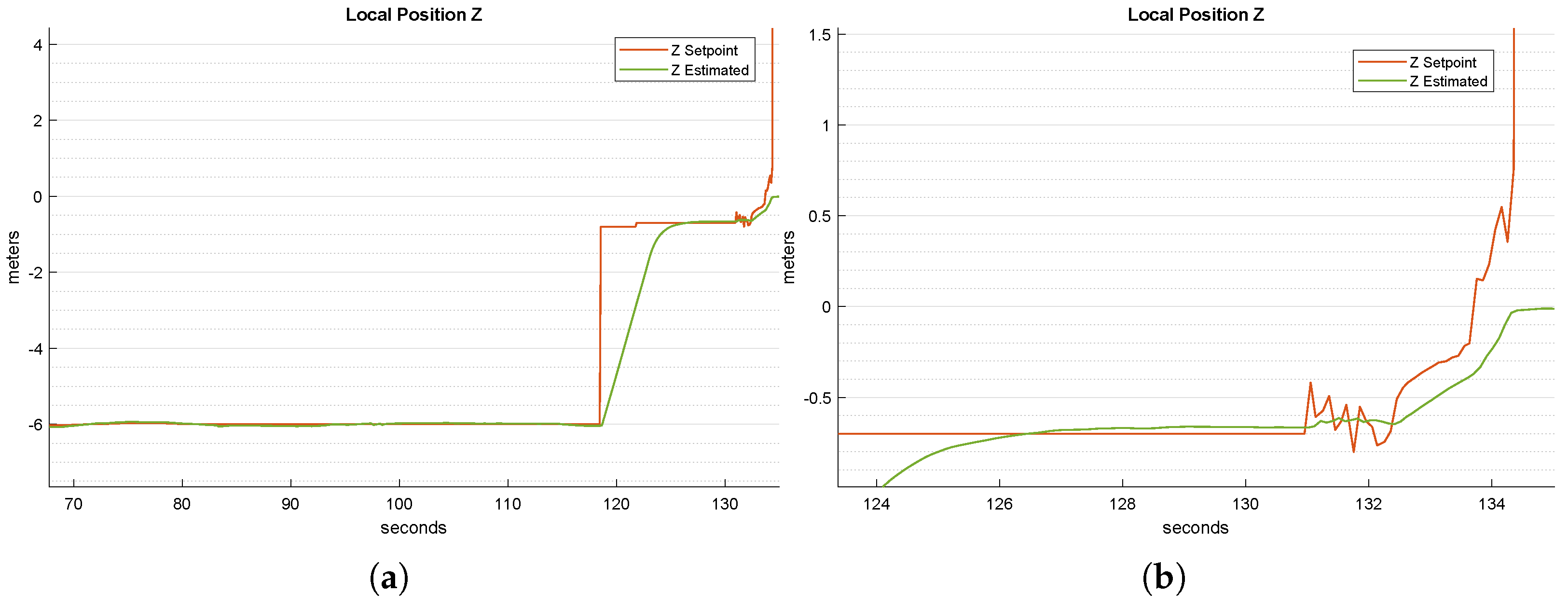
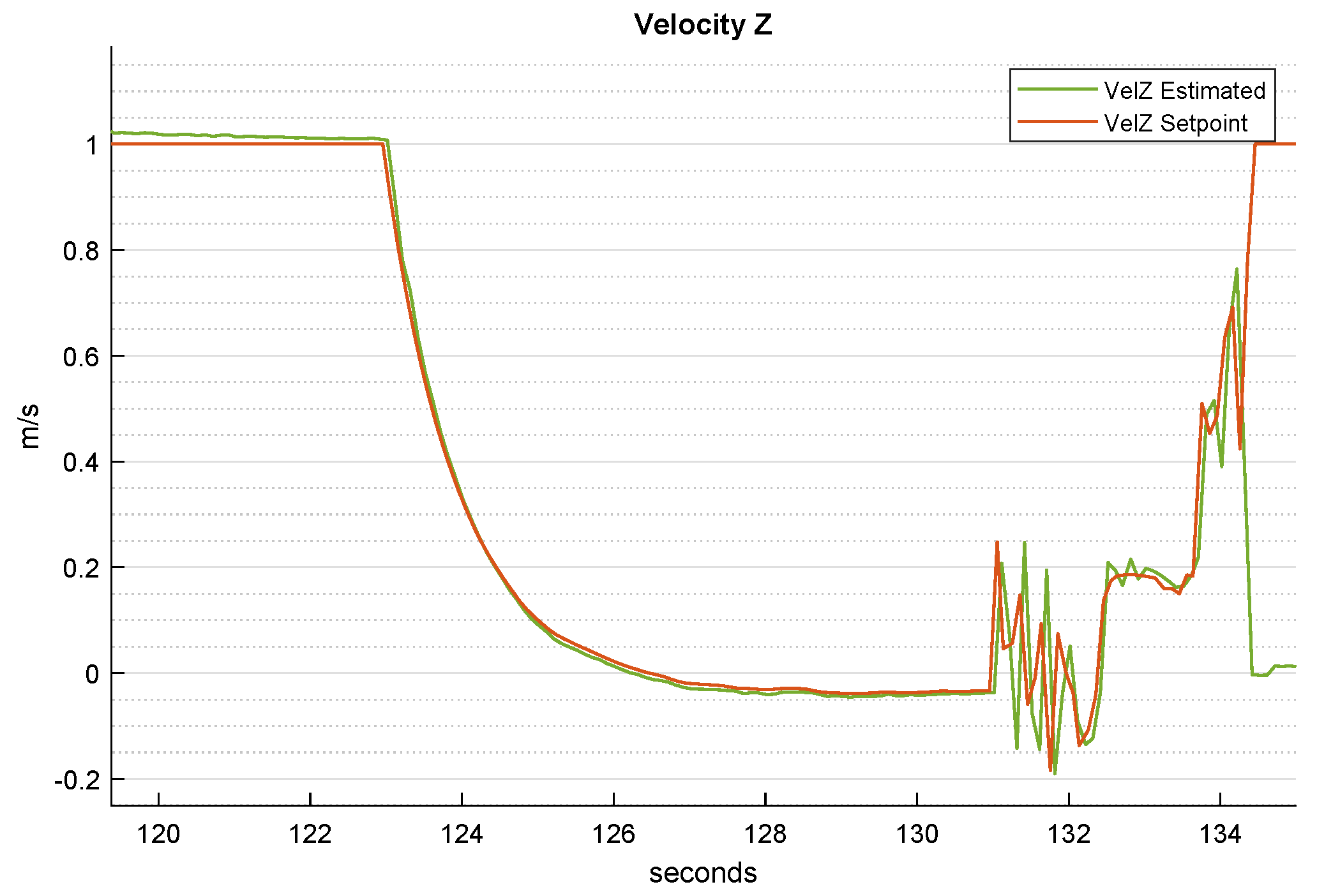
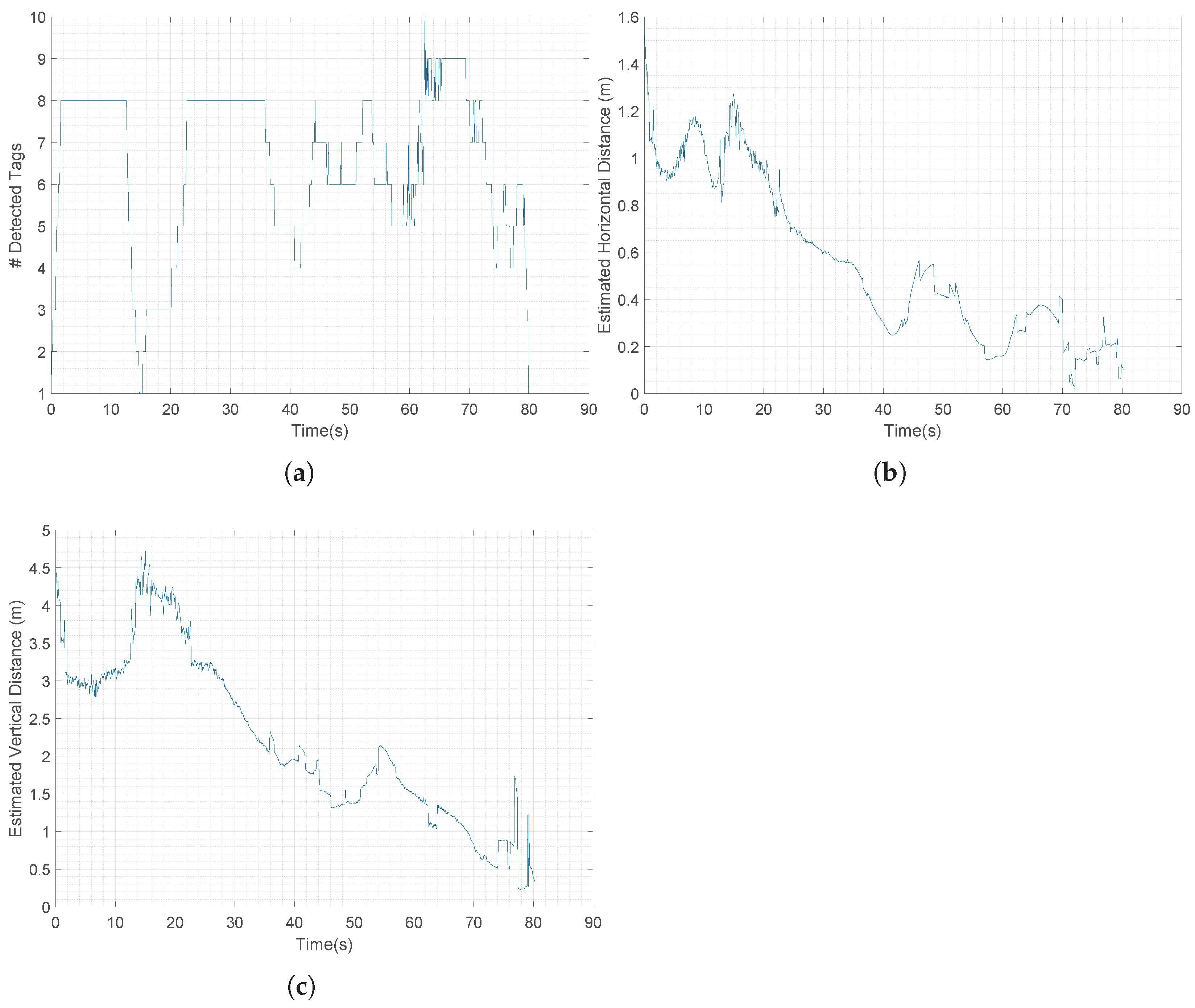
5.2. Vision System Validaton
6. Conclusions
Author Contributions
Funding
Institutional Review Board Statement
Informed Consent Statement
Data Availability Statement
Conflicts of Interest
References
- Tsouros, D.C.; Bibi, S.; Sarigiannidis, P.G. A Review on UAV-Based Applications for Precision Agriculture. Information 2019, 10, 349. [Google Scholar] [CrossRef] [Green Version]
- Boccardo, P.; Chiabrando, F.; Dutto, F.; Tonolo, F.G.; Lingua, A. UAV Deployment Exercise for Mapping Purposes: Evaluation of Emergency Response Applications. Sensors 2015, 15, 15717–15737. [Google Scholar] [CrossRef] [PubMed] [Green Version]
- Jordan, S.; Moore, J.; Hovet, S.; Box, J.; Perry, J.; Kirsche, K.; Lewis, D.; Tse, Z.T.H. State-of-the-art technologies for UAV inspections. IET Radar Sonar Navig. 2018, 12, 151–164. [Google Scholar] [CrossRef]
- Huang, J.; Tian, G.; Zhang, J.; Chen, Y. On Unmanned Aerial Vehicles Light Show Systems: Algorithms, Software and Hardware. Appl. Sci. 2021, 11, 7687. [Google Scholar] [CrossRef]
- Sharma, M.; Gupta, A.; Gupta, S.K.; Alsamhi, S.H.; Shvetsov, A.V. Survey on Unmanned Aerial Vehicle for Mars Exploration: Deployment Use Case. Drones 2022, 6, 4. [Google Scholar] [CrossRef]
- Simetti, E.; Indiveri, G.; Pascoal, A.M. WiMUST: A cooperative marine robotic system for autonomous geotechnical surveys. J. Field Robot. 2021, 38, 268–288. [Google Scholar] [CrossRef]
- Casalino, G.; Allotta, B.; Antonelli, G.; Caiti, A.; Conte, G.; Indiveri, G.; Melchiorri, C.; Simetti, E. ISME research trends: Marine robotics for emergencies at sea. In Proceedings of the 2016 OCEANS, Shanghai, China, 10–13 April 2016; pp. 1–5. [Google Scholar]
- Kong, W.; Zhou, D.; Zhang, D.; Zhang, J. Vision-based autonomous landing system for unmanned aerial vehicle: A survey. In Proceedings of the 2014 International Conference on Multisensor Fusion and Information Integration for Intelligent Systems (MFI), Beijing, China, 28–29 September 2014; pp. 1–8. [Google Scholar]
- Bastianelli Naticchi, N.; Baglietto, M.; Sperindé, A.; Simetti, E.; Casalino, G. Visual Servoed Autonomous Landing on a Surface Vessel. In Proceedings of the OCEANS 2019 MTS/IEEE, Marseille, France, 17–20 June 2019. [Google Scholar]
- Nisticó, A.; Baglietto, M.; Simetti, E.; Casalino, G.; Sperindé, A. Marea project: UAV landing procedure on a moving and floating platform. In Proceedings of the OCEANS 2017, Anchorage, AK, USA, 18–21 September 2017; pp. 1–10. [Google Scholar]
- Abdelkrim, N.; Aouf, N.; Tsourdos, A.; White, B. Robust nonlinear filtering for INS/GPS UAV localization. In Proceedings of the 2008 16 th Mediterranean Conference on Control and Automation, Ajaccio, France, 25–27 June 2008; pp. 695–702. [Google Scholar]
- Gautam, A.; Sujit, P.B.; Saripalli, S. A survey of autonomous landing techniques for UAVs. In Proceedings of the 2014 International Conference on Unmanned Aircraft Systems (ICUAS), Orlando, FL, USA, 27–30 May 2014; pp. 1210–1218. [Google Scholar]
- Yang, X.; Mejias, L.; Garratt, M. Multi sensor data fusion for UAV navigation during landing operations. In Proceedings of the 2011 Australian Conference on Robotics and Automation (ACRA), Melbourne, Australia, 7–9 December 2011; pp. 1–10. [Google Scholar]
- Wang, L.; Bai, X. Quadrotor Autonomous Approaching and Landing on a Vessel Deck. J. Intell. Robot. Syst. 2018, 92, 125–143. [Google Scholar] [CrossRef]
- Falanga, D.; Zanchettin, A.; Simovic, A.; Delmerico, J.; Scaramuzza, D. Vision-based autonomous quadrotor landing on a moving platform. In Proceedings of the 2017 IEEE International Symposium on Safety, Security and Rescue Robotics (SSRR), Shanghai, China, 11–13 October 2017; pp. 200–207. [Google Scholar]
- Verbandt, M.; Theys, B.; Schutter, J.D. Robust marker-tracking system for vision-based autonomous landing of VTOL UAVs. In Proceedings of the 2014 International Micro Air Vehicle Conference and Competition (IMAV), Delft, The Netherlands, 12–15 August 2014. [Google Scholar]
- Araar, O.; Aouf, N.; Vitanov, I. Vision Based Autonomous Landing of Multirotor UAV on Moving Platform. J. Intell. Robot. Syst. 2017, 85, 369–384. [Google Scholar] [CrossRef]
- Olson, E.; Strom, J.; Morton, R.; Richardson, A.; Ranganathan, P.; Goeddel, R.; Bulic, M.; Crossman, J.; Marinier, R. Progress toward multi-robot reconnaissance and the MAGIC 2010 competition. J. Field Robot. 2012, 29, 762–792. [Google Scholar] [CrossRef] [Green Version]
- Mersch, D.; Crespi, A.; Keller, L. Tracking Individuals Shows Spatial Fidelity Is a Key Regulator of Ant Social Organization. Science 2013, 340, 1090–1093. [Google Scholar] [CrossRef] [PubMed] [Green Version]
- Olson, E. AprilTag: A robust and flexible visual fiducial system. In Proceedings of the 2011 IEEE International Conference on Robotics and Automation, Shanghai, China, 9–13 May 2011; pp. 3400–3407. [Google Scholar]
- Simetti, E.; Indiveri, G. Control oriented modeling of a twin thruster autonomous surface vehicle. Ocean Eng. 2022, 243, 110260. [Google Scholar] [CrossRef]
- Huang, A.; Olson, E.; Moore, D.C. Lcm: Lightweight communications and marshalling. In Proceedings of the 2010 IEEE/RSJ International Conference on Intelligent Robots and Systems, Taipei, Taiwan, 18–22 October 2010; pp. 4057–4062. [Google Scholar]


Publisher’s Note: MDPI stays neutral with regard to jurisdictional claims in published maps and institutional affiliations. |
© 2022 by the authors. Licensee MDPI, Basel, Switzerland. This article is an open access article distributed under the terms and conditions of the Creative Commons Attribution (CC BY) license (https://creativecommons.org/licenses/by/4.0/).
Share and Cite
Delbene, A.; Baglietto, M.; Simetti, E. Visual Servoed Autonomous Landing of an UAV on a Catamaran in a Marine Environment. Sensors 2022, 22, 3544. https://doi.org/10.3390/s22093544
Delbene A, Baglietto M, Simetti E. Visual Servoed Autonomous Landing of an UAV on a Catamaran in a Marine Environment. Sensors. 2022; 22(9):3544. https://doi.org/10.3390/s22093544
Chicago/Turabian StyleDelbene, Andrea, Marco Baglietto, and Enrico Simetti. 2022. "Visual Servoed Autonomous Landing of an UAV on a Catamaran in a Marine Environment" Sensors 22, no. 9: 3544. https://doi.org/10.3390/s22093544