
Ultrasonic Sound Guide System with Eyeglass Device for the Visually Impaired


Abstract
:1. Introduction
2. Methods
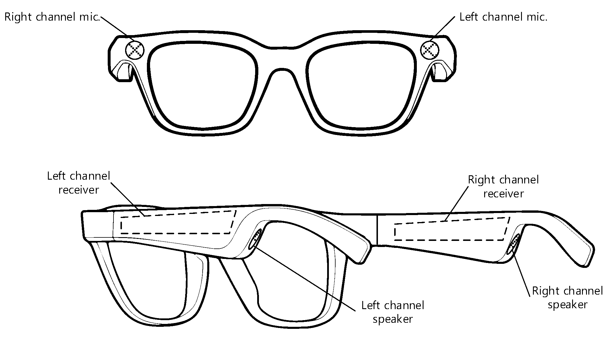
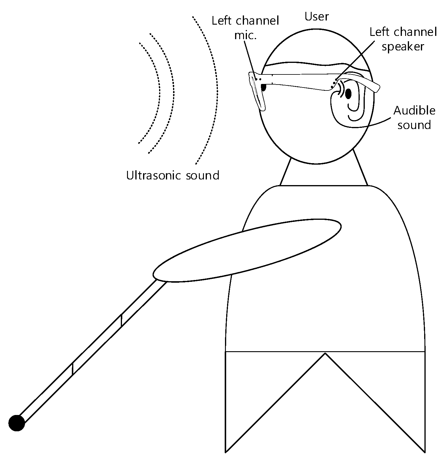
2.1. Receiver Device in the Shape of Eyeglasses
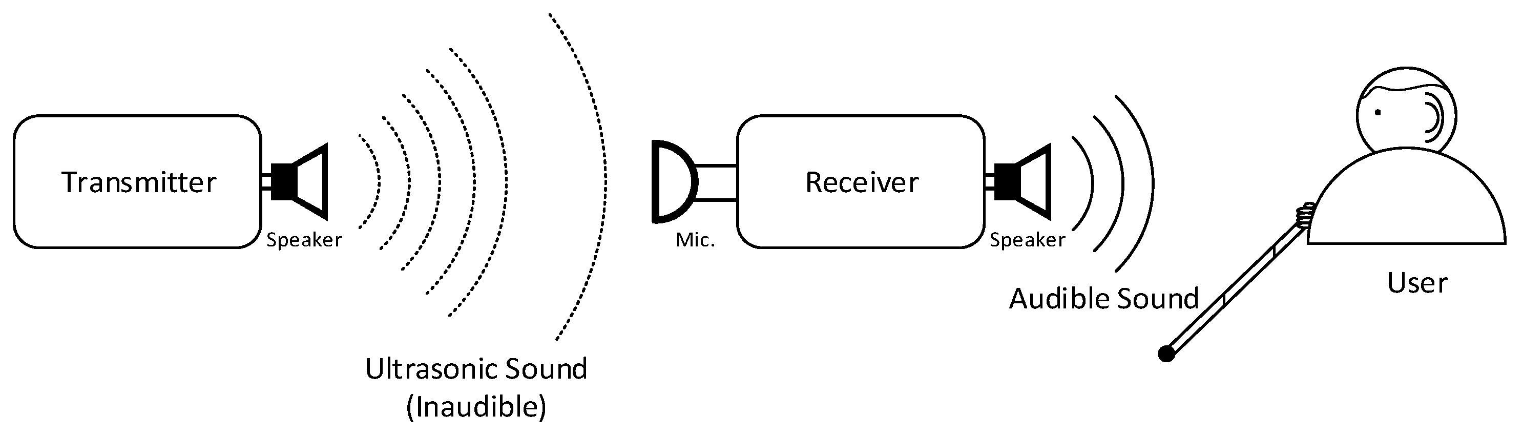
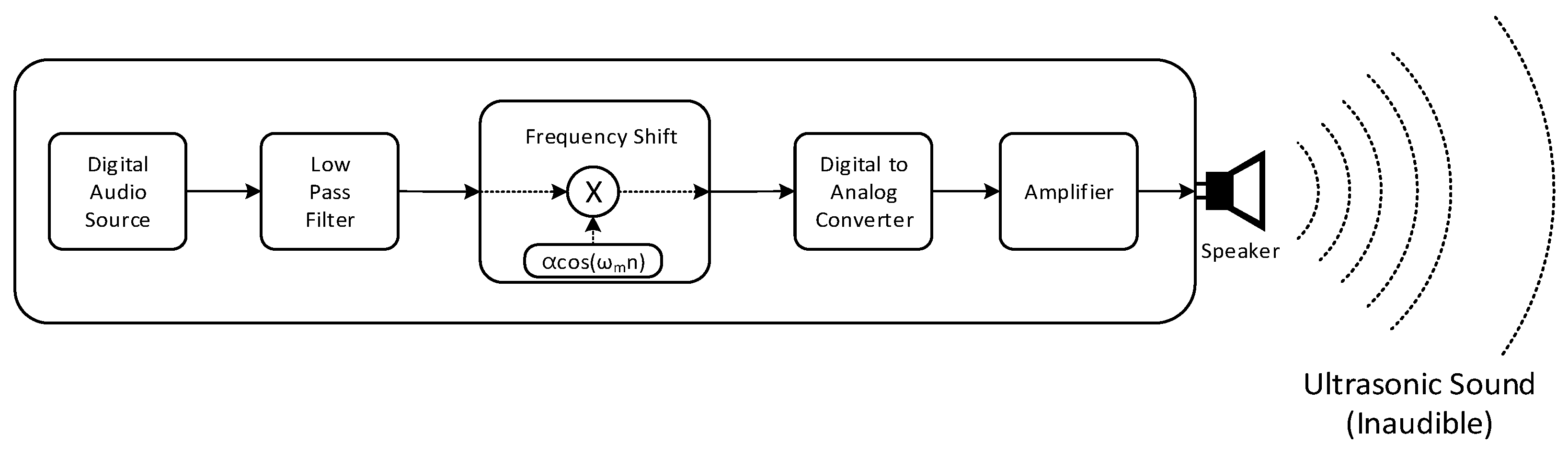
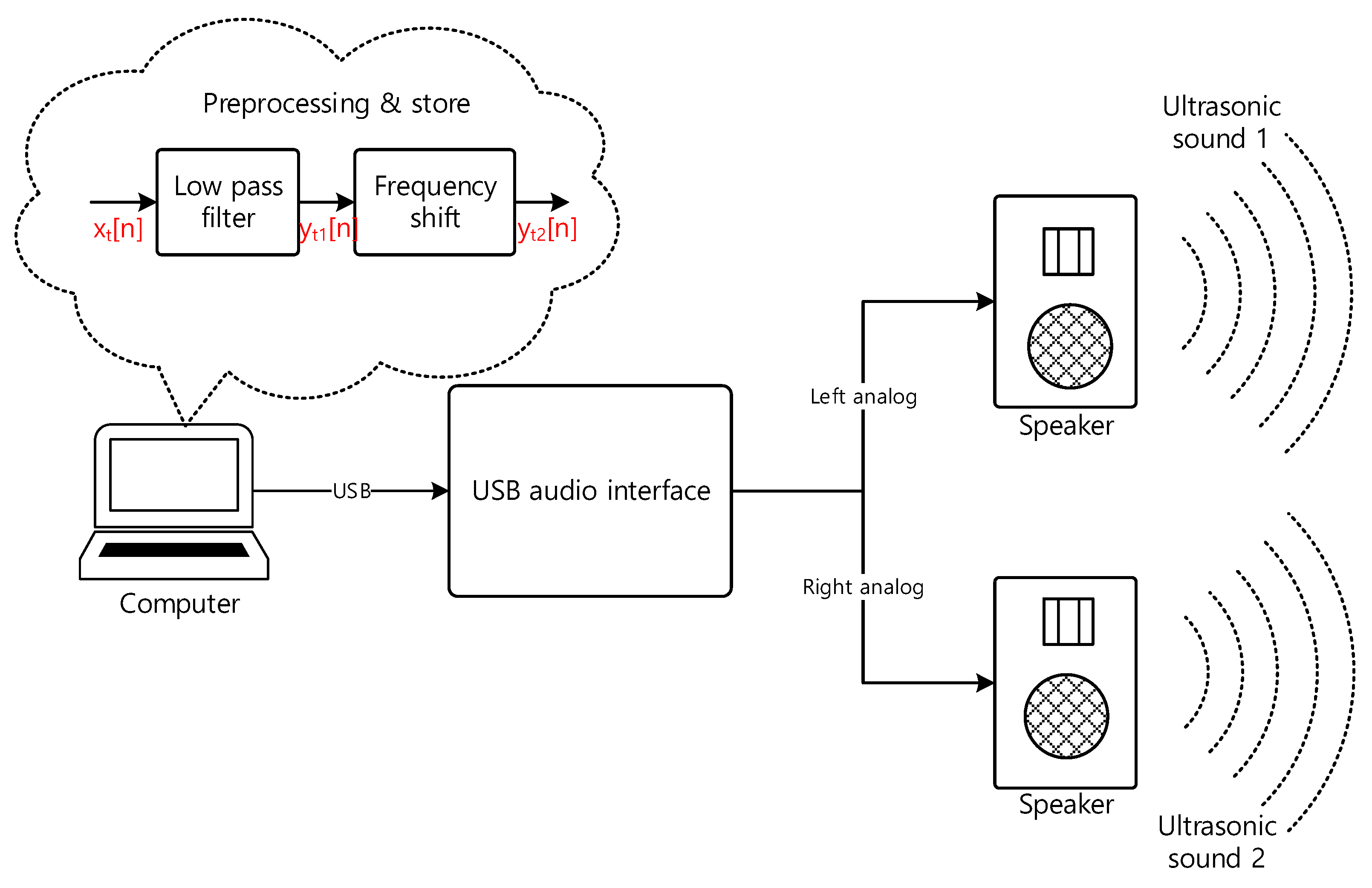
2.2. Transmitter
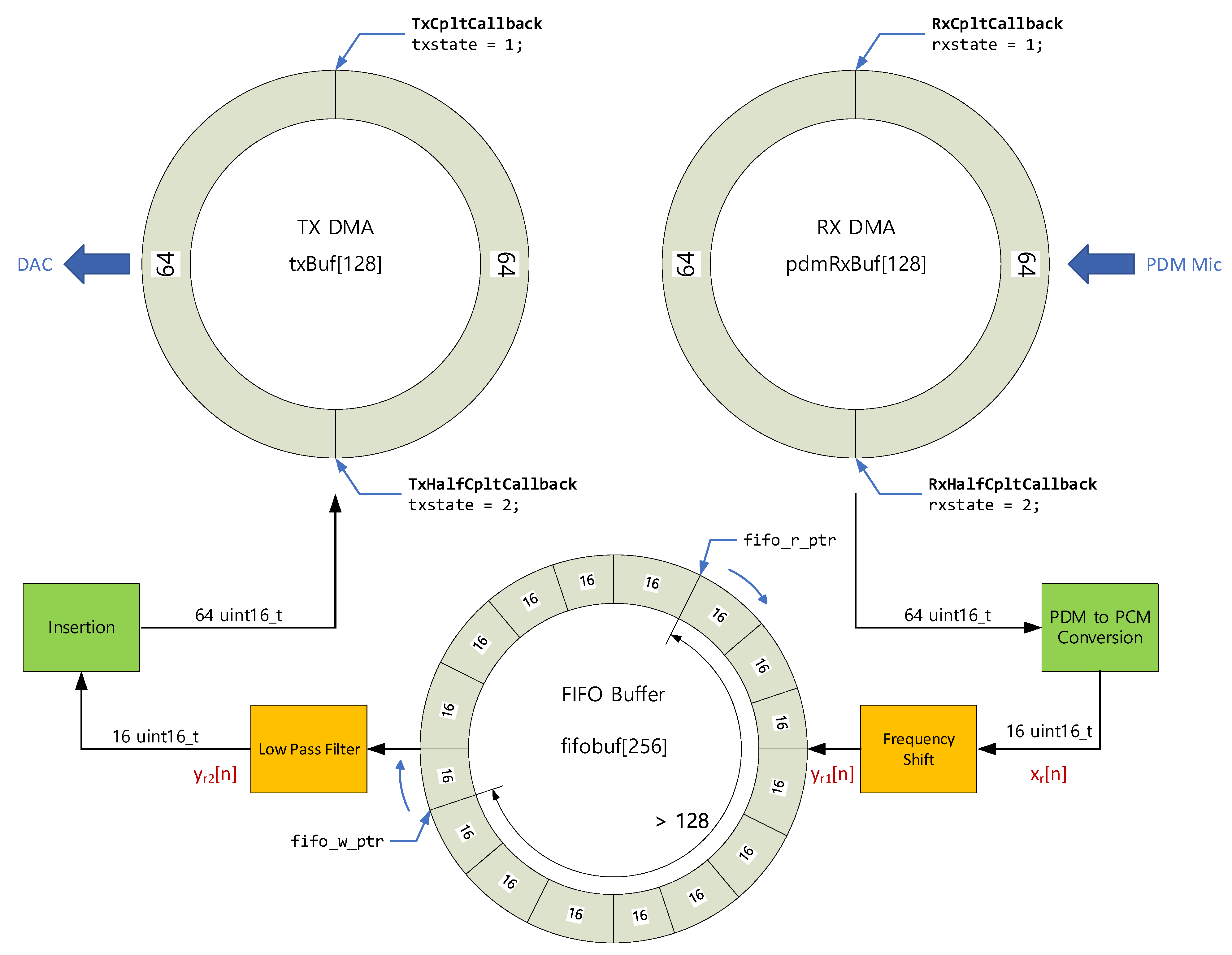
2.3. Receiver
2.4. Localization
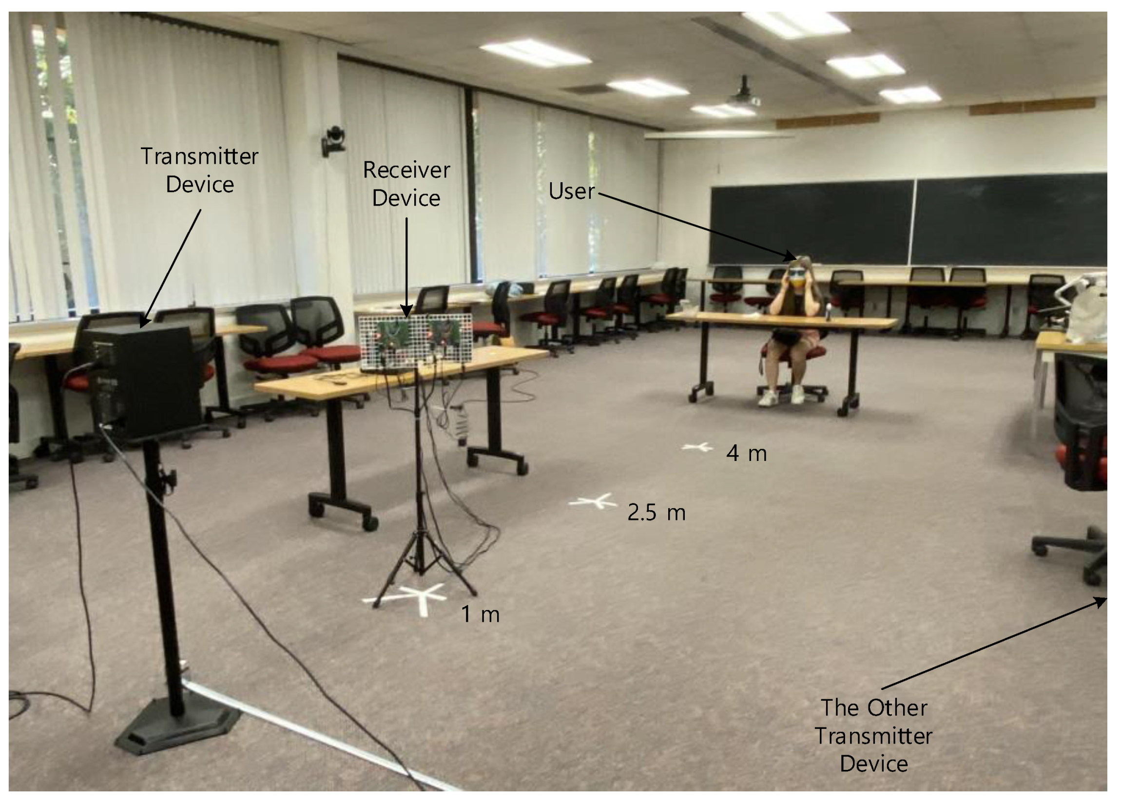
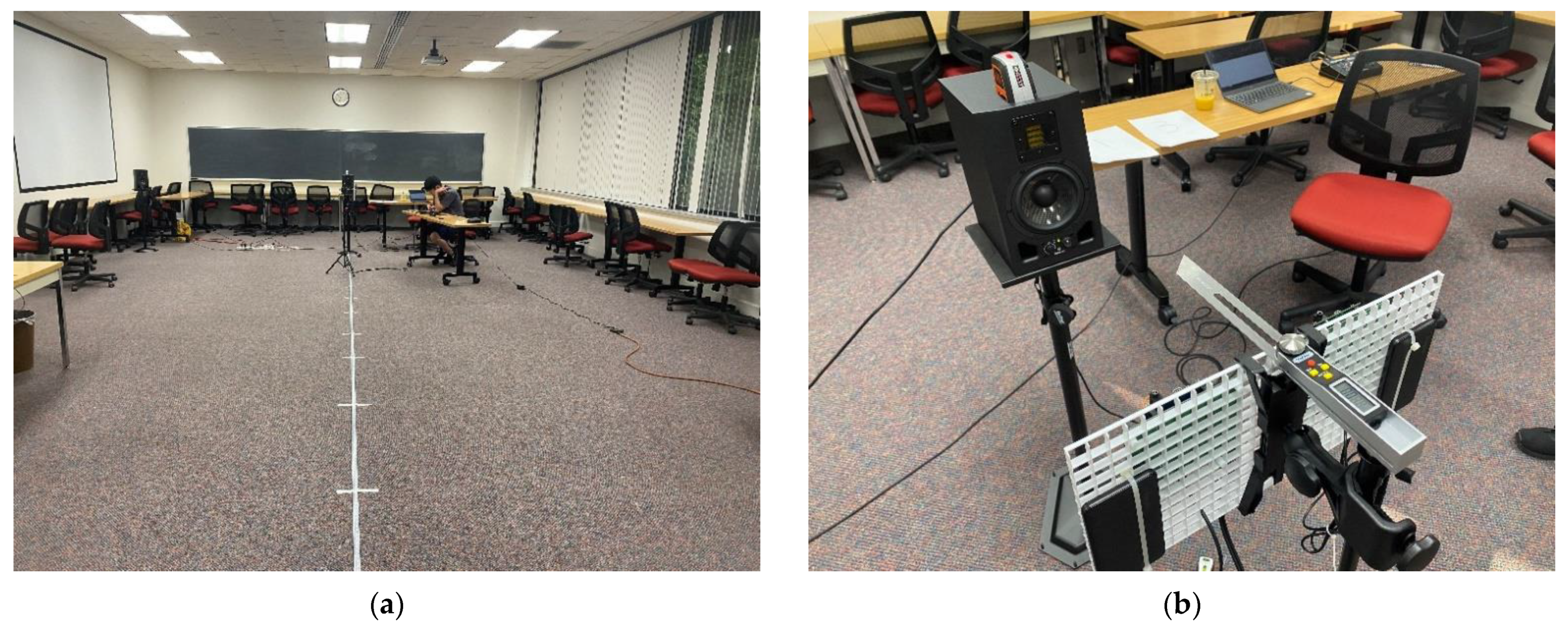
3. Experiments
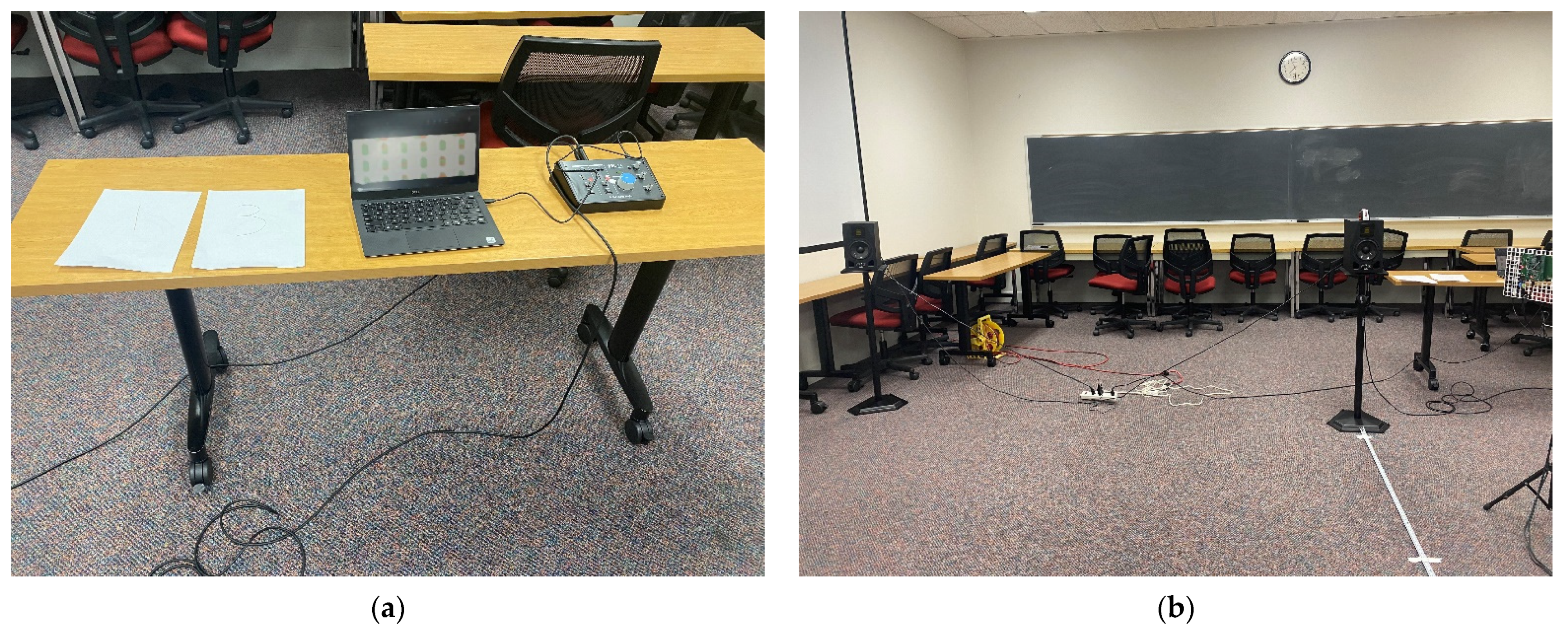
3.1. Realizations
3.1.1. Receiver Device
3.1.2. Transmitter Device
3.2. Scenarios
3.2.1. Human Perception
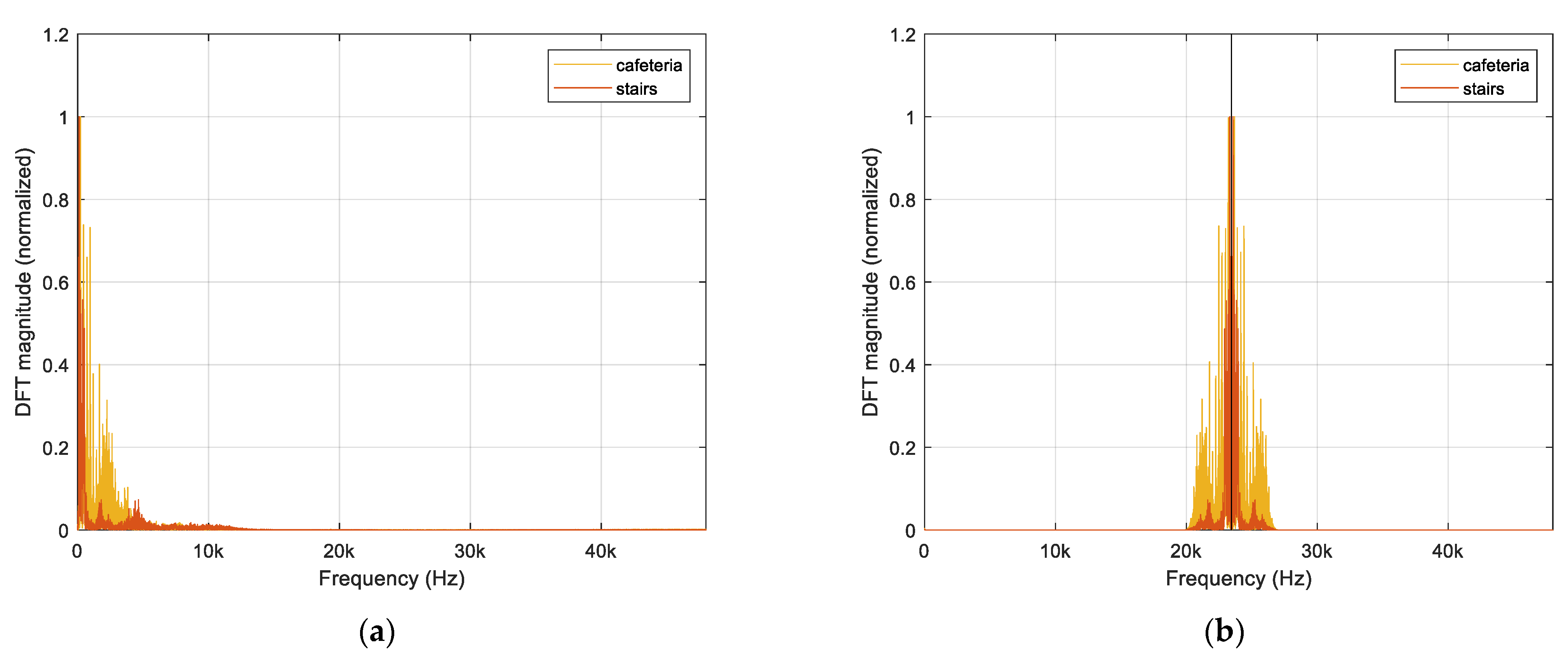
3.2.2. Acoustic Performance
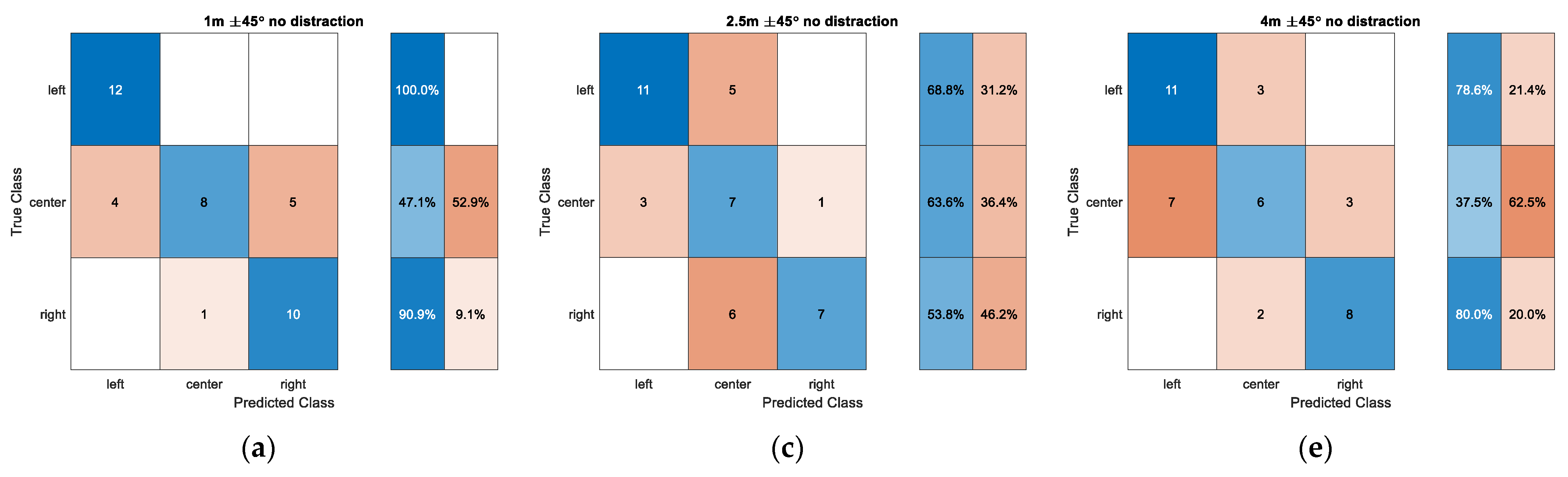
4. Results
5. Conclusions
6. Patents
Author Contributions
Funding
Institutional Review Board Statement
Informed Consent Statement
Data Availability Statement
Acknowledgments
Conflicts of Interest
Abbreviations
| GPS | Global positioning system |
| 3D | Three-dimensional |
| USG | Ultrasonic sound guide |
| ADC | Analog-to-digital converter |
| LPF | Low pass filter |
| DAC | Digital-to-analog converter |
| FPU | Floating-point unit |
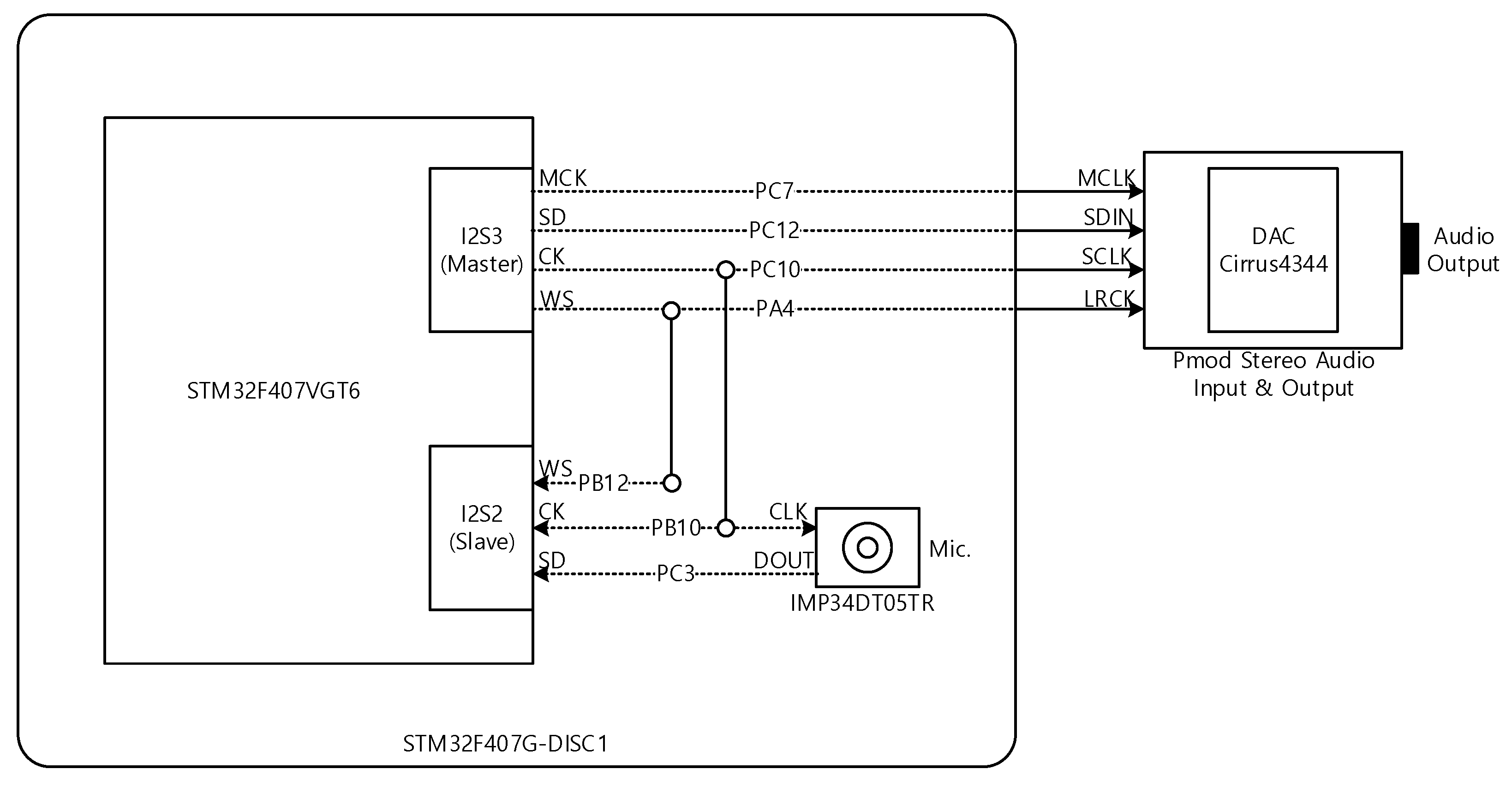
| I2S | Inter-IC sound |
| MCK | Master clock |
| CK | Serial clock |
| WS | Word select clock |
| SD | Serial data |
| PDM | Pulse density modulation |
| PCM | Pulse coded modulation |
| DMA | Direct memory access |
| FIFO | First-in first-out |
| DTFT | Discrete-time Fourier transform |
| FIR | Finite impulse response |
| SP | Single precision |
| CDC | Centers for disease control and prevention |
| SNR | Signal-to-noise ratio |
References
- Lin, B.-S.; Lee, C.-C.; Chiang, P.-Y. Simple smartphone-based guiding system for visually impaired people. Sensors 2017, 17, 1371. [Google Scholar] [CrossRef] [PubMed] [Green Version]
- Budrionis, A.; Plikynas, D.; Daniušis, P.; Indrulionis, A. Smartphone-based computer vision travelling aids for blind and visually impaired individuals: A systematic review. Assist. Technol. 2020, 32, 1–17. [Google Scholar] [CrossRef] [PubMed]
- Velázquez, R.; Pissaloux, E.; Rodrigo, P.; Carrasco, M.; Giannoccaro, N.I.; Lay-Ekuakille, A. An outdoor navigation system for blind pedestrians using GPS and tactile-foot feedback. Appl. Sci. 2018, 8, 578. [Google Scholar] [CrossRef] [Green Version]
- Sugimoto, T.; Nakashima, S.; Kitazono, Y. Development of guiding walking support device for visually impaired people with the GPS. In Applied Computing and Information Technology; Springer: Cham, Switzerland, 2017; pp. 77–89. [Google Scholar]
- Ramadhan, A.J. Wearable smart system for visually impaired people. Sensors 2018, 18, 843. [Google Scholar] [CrossRef] [PubMed] [Green Version]
- Plikynas, D.; Žvironas, A.; Budrionis, A.; Gudauskis, M. Indoor Navigation Systems for Visually Impaired Persons: Mapping the Features of Existing Technologies to User Needs. Sensors 2020, 20, 636. [Google Scholar] [CrossRef] [PubMed] [Green Version]
- Gustafson-Pearce, O.; Billett, E.; Cecelja, F. Comparison between audio and tactile systems for delivering simple navigational information to visually impaired pedestrians. Br. J. Vis. Impair. 2007, 25, 255–265. [Google Scholar] [CrossRef] [Green Version]
- Bharadwaj, A.; Shaw, S.B.; Goldreich, D. Comparing tactile to auditory guidance for blind individuals. Front. Hum. Neurosci. 2019, 13, 443. [Google Scholar] [CrossRef] [Green Version]
- Hartmann, W.M. How We Localize Sound. Phys. Today 1999, 52, 24–29. [Google Scholar] [CrossRef]
- Harkey, D.L.; Carter, D.L.; Barlow, J.M.; Bentzen, B.L. Accessible pedestrian signals: A guide to best practices. In National Cooperative Highway Research Program, Contractor’s Guide for NCHRP Project; Transportation Research Board: Washington, WA, USA, 2007; Available online: https://www.trb.org/Publications/Blurbs/164696.aspx (accessed on 10 November 2021).
- Teaching Students with Visual Impairments LLC, Teaching Students with Visual Impairments. Available online: https://www.teachingvisuallyimpaired.com/auditory-access-devices.html (accessed on 30 November 2021).
- Mashiba, Y.; Iwaoka, R.; Bilal Salih, H.E.; Kawamoto, M.; Wakatsuki, N.; Mizutani, K.; Zempo, K. Spot-Presentation of Stereophonic Earcons to Assist Navigation for the Visually Impaired. Multimodal Technol. Interact. 2020, 4, 42. [Google Scholar] [CrossRef]
- American Council of the Blind, The Audio Description Project. Available online: https://adp.acb.org/museums.html (accessed on 2 December 2021).
- Voicebot.ai., Google Pilots AI-Powered Audio Navigation Tool to Help Visually Impaired People Run Safely. Available online: https://voicebot.ai/2020/11/20/google-pilots-ai-powered-audio-navigation-tool-to-help-visually-impaired-people-run-safely/ (accessed on 5 December 2021).
- National Cooperative Highway Research Program, Guidelines for Accessible Pedestrian Signals. Available online: http://www.apsguide.org/chapter1_aps.cfm (accessed on 30 November 2021).
- Blauert, J. Spatial Hearing: The Psychophysics of Human Sound Localization, Revised ed.; Massachusetts Institute of Technology: Cambridge, MA, USA, 1997. [Google Scholar]
- Stecker, G.; Gallun, F. Binaural hearing, sound localization, and spatial hearing. Transl. Perspect. Audit. Neurosci. Norm. Asp. Hear. 2012, 383, 433. [Google Scholar]
- Wightman, F.L.; Kistler, D.J. Monaural sound localization revisited. J. Acoust. Soc. Am. 1997, 101, 1050–1063. [Google Scholar] [CrossRef] [PubMed] [Green Version]
- Takashima, R.; Takiguchi, T.; Ariki, Y. Monaural sound-source-direction estimation using the acoustic transfer function of a parabolic reflection board. J. Acoust. Soc. Am. 2010, 127, 902–908. [Google Scholar] [CrossRef] [PubMed]
- Ding, J.; Li, J.; Zheng, C.; Li, X. Wideband sparse Bayesian learning for off-grid binaural sound source localization. Signal Processing 2020, 166, 107250. [Google Scholar] [CrossRef]
- Pang, C.; Liu, H.; Zhang, J.; Li, X. Binaural sound localization based on reverberation weighting and generalized parametric mapping. IEEE/ACM Trans. Audio Speech Lang. Processing 2017, 25, 1618–1632. [Google Scholar] [CrossRef] [Green Version]
- Kim, U.-H.; Nakadai, K.; Okuno, H.G. Improved sound source localization in horizontal plane for binaural robot audition. Appl. Intell. 2015, 42, 63–74. [Google Scholar] [CrossRef]
- Baumann, C.; Rogers, C.; Massen, F. Dynamic binaural sound localization based on variations of interaural time delays and system rotations. J. Acoust. Soc. Am. 2015, 138, 635–650. [Google Scholar] [CrossRef] [PubMed]
- Tapu, R.; Mocanu, B.; Zaharia, T. Wearable assistive devices for visually impaired: A state of the art survey. Pattern Recogn Lett 2020, 137, 37–52. [Google Scholar] [CrossRef]
- Kandalan, R.N.; Namuduri, K. Techniques for Constructing Indoor Navigation Systems for the Visually Impaired: A Review. IEEE Trans. Hum. -Mach. Syst. 2020, 50, 492–506. [Google Scholar] [CrossRef]
- Simões, W.C.; Machado, G.S.; Sales, A.; de Lucena, M.M.; Jazdi, N.; de Lucena, V.F. A review of technologies and techniques for indoor navigation systems for the visually impaired. Sensors 2020, 20, 3935. [Google Scholar] [CrossRef]
- Kuriakose, B.; Shrestha, R.; Sandnes, F.E. Tools and Technologies for Blind and Visually Impaired Navigation Support: A Review. IETE Tech. Rev. 2020, 37, 1–16. [Google Scholar] [CrossRef]
- El-taher, F.E.-z.; Taha, A.; Courtney, J.; Mckeever, S. A Systematic Review of Urban Navigation Systems for Visually Impaired People. Sensors 2021, 21, 3103. [Google Scholar] [CrossRef] [PubMed]
- Bai, J.; Lian, S.; Liu, Z.; Wang, K.; Liu, D. Smart guiding glasses for visually impaired people in indoor environment. IEEE Trans. Consum. Electron. 2017, 63, 258–266. [Google Scholar] [CrossRef] [Green Version]
- Pulkki, V.; McCormack, L.; Gonzalez, R. Superhuman spatial hearing technology for ultrasonic frequencies. Sci. Rep. 2021, 11, 1–10. [Google Scholar]
- Tavares, N.P.; Ram, P.S.; Shen, M.C.-Q. Wearable Computing System for Assisting a Visually Impaired User. U.S. Patent 10639228B1, 5 May 2020. [Google Scholar]
- Hendrix, J. Route Guidance and Identification System. U.S. Patent 9429433B2, 30 August 2016. [Google Scholar]
- Sangok, K.; Byungoh, K.; Kim, D. Route Guidance Method and Apparatus for Visually Impaired Using Visible Light Communication Inside Subway Station. U.S. Patent 10441494B2, 15 October 2019. [Google Scholar]
- Campbell, T.L.; Karich, E.K. Mobility Device and Method for Guiding the Visually Impaired. U.S. Patent 8825389B1, 2 September 2014. [Google Scholar]
- Aladas, M. Integrated Accessible Pedestrian System. U.S. Patent 9672732B1, 6 June 2017. [Google Scholar]
- Stimpson, L.E. Assisted Walking Device. U.S. Patent 9044374B1, 2 June 2015. [Google Scholar]
- Hamadallah, H.W. Device, Method and Computer Program Product to Assist Visually Impaired People in Sensing Voice Direction. U.S. Patent 8766765B2, 1 July 2014. [Google Scholar]
- Olson, H.F. Acoustical Engineering; Van Nostrand: New York, NY, USA, 1957. [Google Scholar]
- Fahy, F. Foundations of Engineering Acoustics; Academic Press: Cambridge, MA, USA, 2001. [Google Scholar]
- Brüel & Kjær, Head and Torso Simulator Types 4128-C and 4128-D. Available online: https://www.bksv.com/-/media/literature/Product-Data/bp0521.ashx (accessed on 5 July 2021).
- HEAD Acoustics, HMS II.3 HEAD Measurement System, Basic Version with Right Ear Simulator. Available online: https://cdn.head-acoustics.com/fileadmin/data/global/Datasheets/Artificial_Heads_Binaural_Recording/HMS-II.3-Artificial-Head-1703-Data-Sheet.pdf (accessed on 5 July 2021).
- GRAS Sound & VibrationGRAS, Instruction Manual: GRAS 45BB KEMAR Head and Torso. Available online: https://www.grasacoustics.com/files/m/a/man_45BB_45BC.pdf (accessed on 5 July 2021).
- YetAnotherElectronicsChannel/STM32_PDM_Microphone, STM32 PDM Microphone with I2S Audio Output, GitHub. 2020. Available online: https://github.com/YetAnotherElectronicsChannel/STM32_PDM_Microphone (accessed on 20 June 2021).
- STMicroelectronics. Reference Manual: STM32F405/415, STM32F407/417, STM32F427/437 and STM32F429/439 Advanced Arm®-Based 32-bit MCUs. 2014, p. 902/1751. Available online: https://www.st.com/resource/en/reference_manual/dm00031020-stm32f405-415-stm32f407-417-stm32f427-437-and-stm32f429-439-advanced-arm-based-32-bit-mcus-stmicroelectronics.pdf (accessed on 7 July 2021).
- STMicroelectronics. Application Note: Floating Point Unit Demonstration on STM32 Microcontrollers. 2016, p. 16/31. Available online: https://www.st.com/resource/en/application_note/dm00047230-floating-point-unit-demonstration-on-stm32-microcontrollers-stmicroelectronics.pdf (accessed on 10 July 2021).
- Centers for Disease Control and Prevention, Loud Noise Can Cause Hearing Loss. Available online: https://www.cdc.gov/nceh/hearing_loss/what_noises_cause_hearing_loss.html (accessed on 10 August 2020).


| Block | Parameter | Transmitter Device | Receiver Device |
|---|---|---|---|
| ADC | Sampling frequency (Hz) | 96 kHz | 46.875 kHz |
| Bit resolution (bits/sample) | 16 bits/sample | 16 bits/sample | |
| Frequency shift | Shift amount (Hz) | 23.4375 kHz | 23.4375 kHz |
| LPF | Type/Length | FIR/101 | FIR/21 |
| Cutoff frequency (Hz) | 3.4 kHz | 3.4 kHz | |
| DAC | Sampling frequency (Hz) | 96 kHz | 46.875 kHz |
| Bit resolution (bits/sample) | 16 bits/sample | 24 bits/sample |
| Dist. vs. Ang. | 0.5 m | 1.0 m | 1.5 m | 2.0 m | 2.5 m | 3.0 m | 3.5 m | 4.0 m | 4.5 m | 5.0 m | 5.5 m | 6.0 m | 6.5 m | 7.0 m | Ideal |
|---|---|---|---|---|---|---|---|---|---|---|---|---|---|---|---|
| 90° | 65 | 68 | 48 | 63 | 58 | 48 | 52 | 45 | 43 | 65 | 58 | 67 | 44 | 47 | 54 |
| 60° | 63 | 64 | 53 | 61 | 50 | 60 | 46 | 35 | 59 | 45 | 58 | 59 | 54 | 44 | 46 |
| 30° | 27 | 36 | 26 | 37 | 18 | 35 | 15 | 17 | 30 | 25 | 33 | 28 | 25 | 31 | 27 |
| 0° | 0 | 0 | −2 | 5 | 5 | 6 | 2 | 11 | 12 | 14 | 0 | −4 | −1 | 1 | 0 |
| −30° | −25 | −24 | −25 | −31 | −31 | −40 | −31 | −30 | −24 | −18 | −40 | −22 | −34 | −21 | −27 |
| −60° | −58 | −43 | −47 | −53 | −42 | −59 | −44 | −60 | −53 | −40 | −57 | −40 | −42 | −49 | −46 |
| −90° | −58 | −42 | −55 | −-50 | −48 | −47 | −43 | −51 | −61 | −58 | −51 | −53 | −40 | −30 | −54 |
| Stat. | 90° | 60° | 30° | 0° | −30° | −60° | −90° |
|---|---|---|---|---|---|---|---|
| Mean | 54.92 | 53.61 | 27.49 | 3.62 | −28.12 | −49.11 | −48.95 |
| Stand. dev. | 9.27 | 8.59 | 7.07 | 5.46 | 6.74 | 7.56 | 8.31 |
| Ideal | 53.60 | 46.42 | 26.80 | 0.00 | −26.80 | −46.42 | −53.60 |
| 1.32 | 7.19 | 0.69 | 3.62 | 1.32 | 2.69 | 4.65 |
Publisher’s Note: MDPI stays neutral with regard to jurisdictional claims in published maps and institutional affiliations. |
© 2022 by the authors. Licensee MDPI, Basel, Switzerland. This article is an open access article distributed under the terms and conditions of the Creative Commons Attribution (CC BY) license (https://creativecommons.org/licenses/by/4.0/).
Share and Cite
Kim, K.; Kim, S.; Choi, A. Ultrasonic Sound Guide System with Eyeglass Device for the Visually Impaired. Sensors 2022, 22, 3077. https://doi.org/10.3390/s22083077
Kim K, Kim S, Choi A. Ultrasonic Sound Guide System with Eyeglass Device for the Visually Impaired. Sensors. 2022; 22(8):3077. https://doi.org/10.3390/s22083077
Chicago/Turabian StyleKim, Kevin, Saea Kim, and Anthony Choi. 2022. "Ultrasonic Sound Guide System with Eyeglass Device for the Visually Impaired" Sensors 22, no. 8: 3077. https://doi.org/10.3390/s22083077