1. Introduction
In human–robot cooperation scenarios, humans and robots perform different tasks that should be fulfilled simultaneously in terms of time and space [
1]. Regarding the workers’ safety, many efforts have been applied in order to identify safety areas for the worker to avoid possible collisions [
2,
3]. In addition, several works also pay attention to on the optimization of the task allocation in order to reduce the execution costs required to the worker [
4]. However, in this scenario workers may also have to deal with repetitive tasks, which can become an issue for their health [
5]. To quantify the human risk factors, a lot of methods and tools have been developed for ergonomics assessment. They are usually divided into four categories [
6]: self–report, observational tools, virtual simulations (where digital human models are constructed and their activities are simulated [
7]), and direct measurements (where real data are collected using motion capture system and/or wearable sensors [
8]). In the last category, direct measurements using wearable sensors can be effectively used in real workplaces. The use of inertial measurement units (IMU) allows the assessment of typical ergonomic indices, such as rapid upper limb assessment (RULA), rapid enter body assessment (REBA), posture evaluation index (PEI), workcell evaluation index (WEI), Ovako working posture analyzing system (OWAS), and European Assembly Work-Sheet (EAWS), as presented in different works [
7,
9,
10]. In addition, it has been demonstrated that significant biomechanical and physiological changes in fatigued muscles can be assessed using surface electromyography (sEMG) signals [
11]. In this context, a wearable sensors system composed of IMU and sEMG sensors has also been used in real time to monitor workers by measuring muscular efforts and postures for the evaluation in parallel with typical ergonomic indices such as RULA [
12].
Although this ergonomic analysis can also be carried out in real time, the possibility to have a continuous interaction with the industrial environment is very poor. In this context, a possible strategy is to use human–in–the–loop virtual reality (VR) technologies. Indeed, these technologies guarantee the accuracy of ergonomic analysis by incorporating human–in–the–loop in the simulation of a realistic environment. For this aim, consumer VR devices such as VR headsets (e.g., HTC Vive, Oculus Rift, and Samsung Gear VR) provide the users with an immersive experience [
13]. The usability of these technologies can be evaluated using different subjective multidimensional measures to assess the workload, such as NASA Task Load Index (NASA–TLI) or System Usability Scale (SUS) [
14]. These interactive technologies can be used to try different workplace configurations and, at the same time, to give the worker real–time feedback about his ergonomic status during the execution of the task. In this field, recently, the authors of [
15] developed a VR platform on Unity 3D, an open-source software with models of collaborative robot (i.e., cobot), enabling kinematic modeling and control of robots using tracked controllers. Another possible open–source software useful for robotic simulation in VR is CoppeliaSim. Indeed, the CoppeliaSim VR Toolbox provides a set of tools to experience robot simulation in VR and to return user interactions [
16].
The literature presents several VR systems with the integration of the ergonomic evaluation. For example, in [
17], the authors presented a VR system for ergonomic analysis in aircraft assembly using as VR platform Unity 3D with Oculus sensor as VR device. The ergonomic analysis was performed using MS Kinect data and the ergonomic evaluation was based on RULA and REBA scores. However, the system did not offer the possibility of a real–time evaluation. Another interesting example is the VR–Ergo log system [
18], an immersive VR system (developed using HTC Vive) combined with an IMU system (integrated with heart rate monitoring) that allows to obtain an ergonomic assessment. The data collected with the IMU system are used to move a digital human model (Jack from Siemens) and are processed in real time with the assessment of RULA, OWAS, OCRA, and lifting index. However, the system did not allow the acquisition of EMG data. This latter aspect has been underlined by the authors in [
18] as future work worth investigating.
In summary, although it is well established within the ergonomics discipline that muscular effort can lead to discomfort and injuries [
19], none of the presented VR systems show a real–time ergonomic assessment based on muscular activity evaluation. In this context, the main contribution of our VR system is to show, in real time, the EMG–based ergonomic evaluation within the immersive virtual environment. For this aim, we propose a VR system that combines the use of wearable sensors for a real–time assessment of cooperative workplaces from the ergonomic point of view. To this end, we used the robotic simulator CoppeliaSim in combination with sEMG sensors and an accelerometer. The proposed approach has been tested in a real use case of a cooperative workplace, which consists of a pick–and–place task in the automotive industry.
2. System Architecture
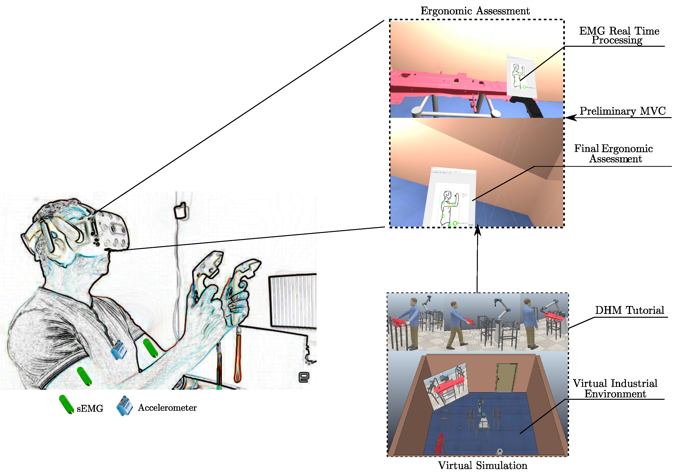
Figure 1 shows the architecture used in this work. In our system, we use a mixed–prototyping strategy involving VR environment, computer–aided design (CAD) objects, and human subject [
20,
21]. The real industrial environment is reconstructed in the robotic simulator CoppeliaSim. In particular, the objects of the virtual environment are created using a standard CAD software (i.e., CATIA) while the cobot is directly found in the CoppeliaSim model library. In the simulation, the user’s interaction with the environment is guaranteed by consumer virtual reality devices (i.e., headset, tracking system, and controllers). In addition, an associated tutorial through a digital human model (DHM) is implemented (first sequence of images in the block “virtual simulation” in
Figure 1). For the ergonomic assessment, a user is asked to perform all the tasks required by industrial use case. A tool for the real–time acquisition and processing of biosignals through wearable sensors is developed in Matlab environment (block “Ergonomic Assessment” in
Figure 1). In detail, the ergonomic assessment is performed using multiple sEMG sensors placed on a specific user’s muscle and one accelerometer located at the end of the vertebral column. Preliminary data related to maximum voluntary contraction (
) of the worker are required for a correct evaluation. The output of the ergonomic analysis, i.e., the “EMG Real Time Processing” and the “Final Ergonomic Assessment” (at the end of the task), are then shown within the immersive environment in real time. In the next two sections, the methodology used to realize the virtual reality simulations and ergonomic assessment are presented.
4. Ergonomic Assessment
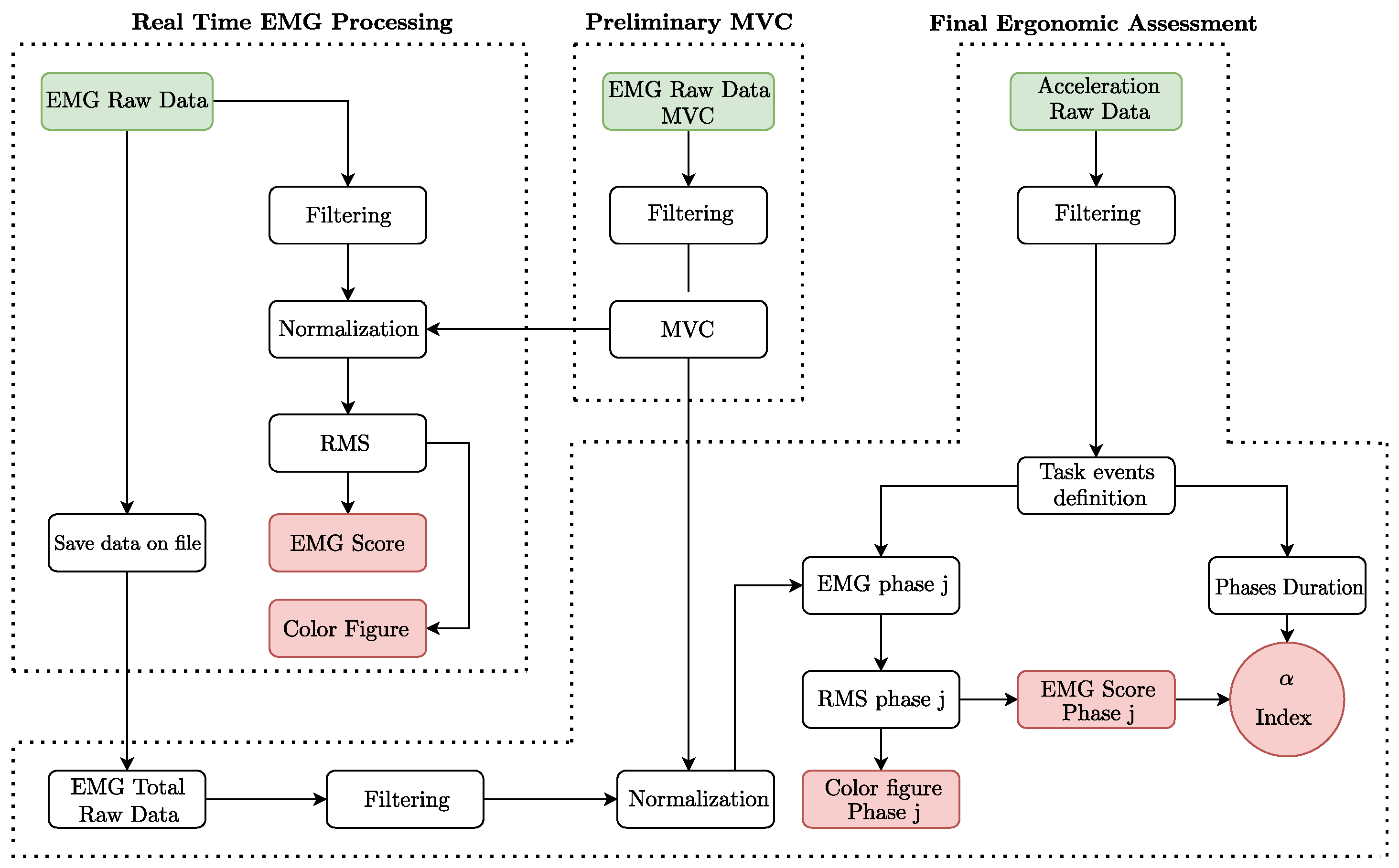
In this section, the operations defined for the ergonomic assessment in real–time and in post–processing are explained in detail. The sEMG sensors and an accelerometer are employed to acquire, respectively, muscle activation and kinematic data for biomechanical events assessment during the virtual reality simulation. The data processing, implemented in Matlab environment starting from the data collected with wearable sensors, is schematized in
Figure 2. It is divided into three main sections (see dashed lines in
Figure 2): preliminary MVC, real–time EMG processing, and final ergonomic assessment. The most important outputs of each section are contained in red blocks, as can be seen in
Figure 2.
4.1. Preliminary MVC
This is a preliminary section which takes place before the real–time acquisition. In this phase, the user’s s are acquired and filtered with a moving average filter and a Butterworth low–pass filter. These specific parameters are defined according to the characteristics of the industrial task. The final output is to obtain the for each muscle under investigation, which will be used during the real-time processing and for the final ergonomic assessment in order to normalize the sEMG signals.
4.2. Real Time EMG Processing
The purpose of this section is to collect and to process, in real time, the data from the sEMG sensors. This data processing is applied each second during the execution of the task. The processing starts with the same filtering operation described in the previous subsection. Then, using the
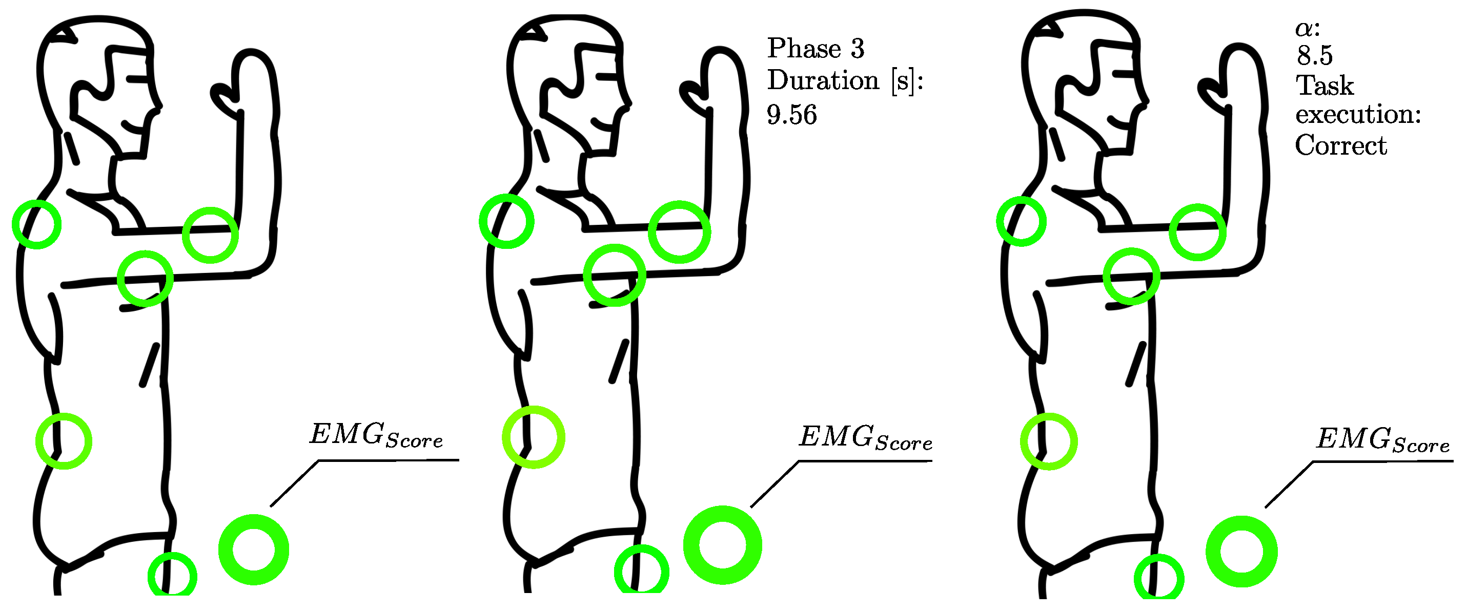
values previously obtained, the signals are normalized. Starting from the normalized sEMG values, the following operations are carried out: (i) calculation of RMS values; (ii) definition of a color based on RMS values; (iii) printing a specific image to show the level of muscle activation on the body (see
Figure 3); (iv) definition of the
, an average of the RMS values; and (v) saving data on a .txt (which will be the input of the final ergonomic assessment). For the point (ii), in order to obtain a specific color for each RMS value, we consider the RGB color space, in which all the colors are obtained from the combination of the red (R), green (G), and blue (B) colors. Thus, the definition of the color related to each index is carried out according to the following system of equations:
or:
The points (iii) and (iv) are the main outputs of this section. Indeed, once the colors are determined they are plotted on an image (showing a human body shape, see
Figure 3) through a circle for each muscle and a circle for the
. The
assessment is obtained according the following equation:
where
i is the generic index that represents the single muscle and
n is the total number of muscles involved in the ergonomic evaluation.
4.3. Final Ergonomic Assessment
This section starts as soon as the time specified for the real-time acquisition ends. Its main purpose is evaluating a synthetic ergonomic index for the specific phase of the task. For this aim, a set of phases are defined from the the identification of specific events on the center of mass (CoM) vertical acceleration graph of the whole task. In addition, in order to delete the phase shift, signals are filtered two times (in both the directions). Thus, also for this section, the sEMG signals are filtered and normalized, as descried in the previous subsection. Then, the RMS value and the
(with the related color) are assessed and, finally, a specific image is printed for each phase of the task. The last output of this section is a synthetic index, called
, that is a weighted average of the
evaluated for the single phases. It is defined according the following equation:
where
i is the generic index that represents a single phase of the task,
is the time duration of the generic phase
i,
m is the number of the phases composing the task, and
is the total time of the whole task.
5. Experiments
In this section, the proposed methodology exposed is applied in a real industrial use case. This use case is part of the Integrated and COllaborative Systems for the smArt Factory (ICOSAF) project, which aims to develop and integrate technologies and solutions for a collaborative factory with a growing integration of the operator with collaborative automation systems.
5.1. Use Case Description and Implementation
The use case of this work involves a human–robot workplace where the cobot is represented by a UR10 robot. The device automatically checks the quality of welds, through big data elaborations by a computer, and gives to the worker information about the quality of the process and about the maintenance status. The cobot checks the quality of the welds through an ultrasound tool placed as the end–effector. The work cycle hypothesized for the use case is divided into the following steps:
Pickup of a metal component from the load stand. The component is an assembly of metal parts that arrives to the control spot already assembled. It weighs 3.4 kg.
Manual transport of the component to the robot stand.
Wait until the robot analyzes each one of the 50 welding points on the component.
According to the overall work cycle description, the human task can be divided into the following phases: (i) bend and reach plus grasp (): the phase in which the worker leans to pick up the component; (ii) arise from bend, get (): the phase in which the worker stands up while holding the component; (iii) turn body and walk (): the phase in which the worker turns and walk to the examination stand while holding the component; (iv) bend and reach (): it is another leaning phase in which the user leans to place the component on the robot stand; (v) positioning (P): the user takes some time to place the component while he is leaning; (vi) arise from bend, put (): the phase in which the worker stands up not holding the component.
In order to recreate the virtual environment according to the system architecture exposed in
Section 2 in CoppeliaSim, the industrial use case was built with all objects required. In addition, the robot with an appropriate end–effector was able to move on the welds control points. A DHM included in the CoppeliaSim library is programmed to simulate the task for the development of the virtual tutorial. In addition, to make the training more effective, some panels with extra instructions about the task were created and programmed to appear during specific moments of the work cycle simulated by the DHM (e.g., when the DHM picks up the component or when he presses the button). The same scenario, without the DHM, was used for VR simulations where there is the possibility to interact with the objects in the scene using HTC–Vive controllers. In particular, for the user’s interaction, different functions were programmed: (i) to pick the component; (ii) to start robot examination; (iii) to help the user to put the component in the correct position. Finally, an additional feature was implemented to help the user in the positioning of the component on the examination stand based on the collision detection mechanism of CoppeliaSim.
5.2. Experimental Setup
The experiments were conducted in the MARTE laboratory of the University of Naples Federico II (Fraunhofer Joint Lab IDEAS—Cesma). The laboratory is equipped with an HTC-Vive system composed of a headset, two base stations, and two controllers. The base stations were mounted on two tripods with an inclination of 45
downward. They were positioned in the opposite corners of a square defining a tracking area of 25 m
2. The experiments involved a male volunteer, 166 cm tall, with body mass of 62 kg, who had to replicate the task described in
Section 5.1 while wearing wearable sensors.
According to the goal exposed in
Section 4, the wearable sensors chosen were part of the Bitalino Revolution Board Kit. It is a biosignals acquisition wearable board equipped with Bluetooth, with the possibility to connect at the same time up to six sensors. For the proposed methodology, five sEMG sensors (dynamic range ±1.64 mV; sample frequency: 1000 Hz) placed on specific muscles and one uniaxial accelerometer (dynamic range: ±3 g; sample frequency: 1000 Hz) placed at the bottom of the vertebral column at L5 level (approximately the height of CoM) were used.
The muscles to be monitored were chosen after carrying out a comparison with similar tasks, according to literature [
22] and after a research on muscles activation in response to specific movements, such as as the SENIAM project [
23]. The muscles considered were the following: biceps brachii (
), long head of the triceps brachii (
), anterior deltoid (
), erector spinae at L3 level (
), and rectus femoris (
). To place the electrodes on the selected muscles in the correct positions, the indications from the SENIAM project were followed [
23]. Before moving on with the real-time acquisition, the
for each muscle had to be collected to perform normalization on the EMG signals. For this aim, specific exercises suggested by SENIAM for each muscle under investigation were carried out. According to the characteristics of the industrial task, the following filter parameters were applied: moving average filter with a time window of 150 ms and a Butterworth low-pass filter fourth-order with a cut-off frequency of 2 Hz [
22]. For the acceleration, a fourth-order Butterworth low–pass filter was applied with a cut-off frequency of 2 Hz (six times the frequency of stride, according to [
24]). In order to make the Bitalino Revolution Board wearable, a 3D case specifically made for the board was 3D printed. It was attached to the user’s belt, so that he could easily drag it around during the acquisition. In addition, in order to give to the user the weight feedback of the handled metal component, he was equipped with two weights fixed on his wrists. In this way, actual responses from the sEMG sensors were obtained. The weights used are 2 kg each, which approximate the weight of the real metal component.
5.3. Experimental Results
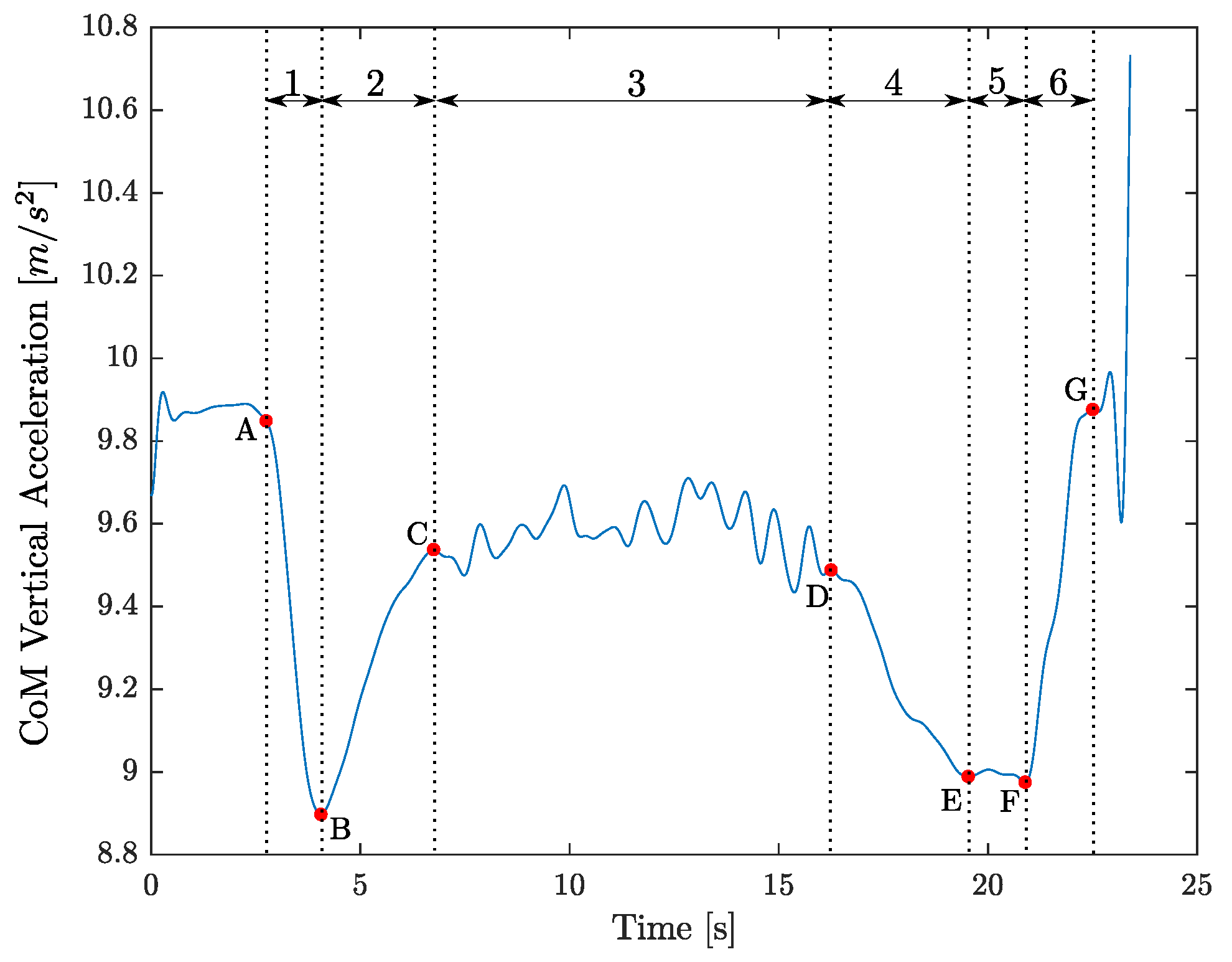
The industrial task was replicated by the voluntary. The phases of the whole task, individuated in
Section 5.1, were defined and described in relation to the vertical CoM acceleration graph through the identification of notable points related to the specific events (
Figure 4):
BRG: The
phase is defined as the time that elapses between the first instant of the worker bending in front of the load stand, called event A, and the instant in which the worker grasps the metal component (called event B). The
timing is so expressed equal to
where
is the first temporal instant of the minimum of the vertical CoM acceleration under a threshold (fixed equal to
= 0.9 g);
is assessed starting from the point B, coming back as the previous first temporal instant of the maximum.
ABG: The
phase is defined as the time that elapses between the event B and the instant in which the worker returns to standing up straight (called event C). The
timing is so expressed equal to
where
is assessed starting from the point B as the following first temporal instant of the maximum.
TBW: The
phase is defined as the time that elapses between the event C and the first instant of the worker bending in front of the robot (called event D). The
timing is so expressed equal to
where
is assessed starting coming back from the point E (related to
, that is the first temporal instant of the minimum of the vertical CoM acceleration under the threshold
after the point C) as the previous first temporal instant of the maximum.
BR: The
phase is defined as the time that elapses between the event D and the event E (the instant in which the worker starts the positioning of the metal component on the robot stand). The
timing is so expressed equal to
P: The
P phase is defined as the time that elapses between the event E and the instant in which the worker ends the positioning of the metal component on the robot stand (called event F). The
P timing is so expressed equal to
where
is assessed starting from the point E as the last temporal instant of the minimum under the threshold
.
ABP: The
phase is defined as the time that elapses between the event F and the instant in which the worker returns to standing up straight (called event G). The
timing is so expressed equal to
where
is assessed starting from the point F as the following first temporal instant of the maximum.
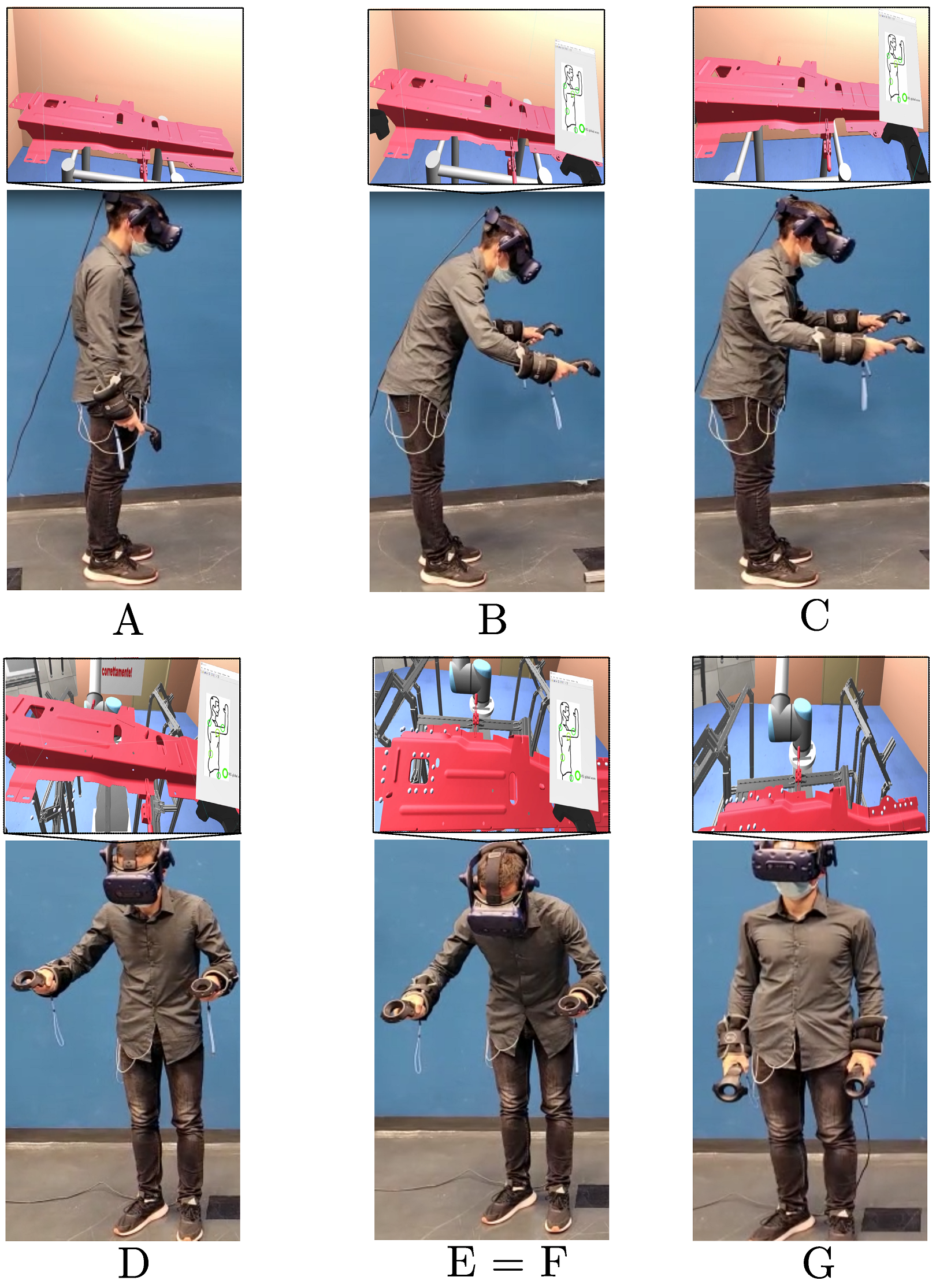
According to events defined on the vertical CoM acceleration graph (see
Figure 4), the related highlights from the real task and from the virtual task are shown in
Figure 5. A summary of the results collected for each phase is reported in
Table 1. According to these values, the obtained
index was equal to 8.5.
6. Discussion
The final ergonomic assessment obtained with the proposed system (shown in
Table 2) underlines how the task under investigation is not very demanding for the user. These results are in accordance with a typical ergonomic evaluation carried out by virtual simulation using a digital human model (Jack, Siemens) that defined the constraints according to the use case characteristics (described in
Section 5.1). Indeed, the ergonomic indices obtained for the fifth male percentile (which represents the volunteer’s characteristics) show values of no risk (i.e., RULA < 3 and REBA < 2) or low risk (i.e., RULA < 5 and REBA < 4). In addition, the
values are included in a non-critical range. Indeed, they are between 0.66 and 1.31 with none of the three terms assuming values above 1.
In addition, we also tested the usability of the proposed system. The evaluation of the task obtained using the NASA–TLI questionnaires, according to the data collected by the volunteer, is reported in
Table 3. The “Weights” underline how “Mental Demand” and “performance” are considered as the most important variables, while “temporal demand” is the least important one. For the “Rating” assessment, “mental demand”, “physical demand”, and “effort” had the highest loading (i.e., between 25 and 30) that, in accordance with the literature, can be interpreted as a medium workload [
25]. Finally, starting from the collected data, the global score of the NASA-TLI is equal to 24 (which can also be considered as a medium workload [
25]).
Limitations
Firstly, the sample size was very limited; indeed, the VR system was tested in only one scenario and with only one unskilled volunteer. Future works will be focused on testing the proposed system architecture with a statistically significant sample of industrial workers with different genders that cover a wide range of stature percentiles of the selected population. Despite this limitation, the main goal of this work, consisting of presenting a new sensor-based framework for VR, was achieved. Secondly, regarding the ergonomic evaluation, the main limitation is that our VR system does not consider classical ergonomic indices (such as RULA, REBA, and OWAS). Although for these indices a comparative evaluation in virtual simulation was carried out through Jack software, future development will consider the integration of an IMU sensor system to integrate the actual ergonomic analysis with RULA and REBA scores in the real-time ergonomic assessment. Despite this limitation, this work uses an established approach for ergonomic analysis through the use of sEMG sensors. Thirdly, regarding usability, an actual limitation of the proposed system is the users’ difficulties in wearing the sEMG sensors. This issue, also common for other sensors used in VR systems [
26], can be overcome with the use of wearable clothes with textile electrodes [
27].
7. Conclusions
In this work, we presented the definition of a virtual reality system composed of a robotic simulator (with headset and controllers) combined with the use of surface electromyography sensors and accelerometer for real-time testing and validation of cooperative workplaces. Then, we applied the system to a real industrial use case related to a human–robot task in the automotive industry. The results showed that a worker is able to understand and perceive his ergonomic status and safety conditions while he is directly performing the task in the immersive virtual environments. We report two evaluations: (1) quantitative evaluation, with respect to empirical methods for ergonomic assessment; (2) qualitative evaluation, in terms of usability of the proposed EMG-based VR system. With respect to the first evaluation, we can consider the EMG-based ergonomic indices valid. With respect to the second evaluation, we can consider that the global workload on the operator can be considered as medium. Future works can be focused on testing the proposed system with a statistically significant sample of industrial workers with different anthropometric characteristics, including multiple IMU to obtain more kinematic data, and using textile electrodes for sEMG sensors to improve the wearability of the system.


