
Wideband Versatile Receiver for CubeSat Microwave Front-Ends

Abstract
:1. Introduction
2. Related Works
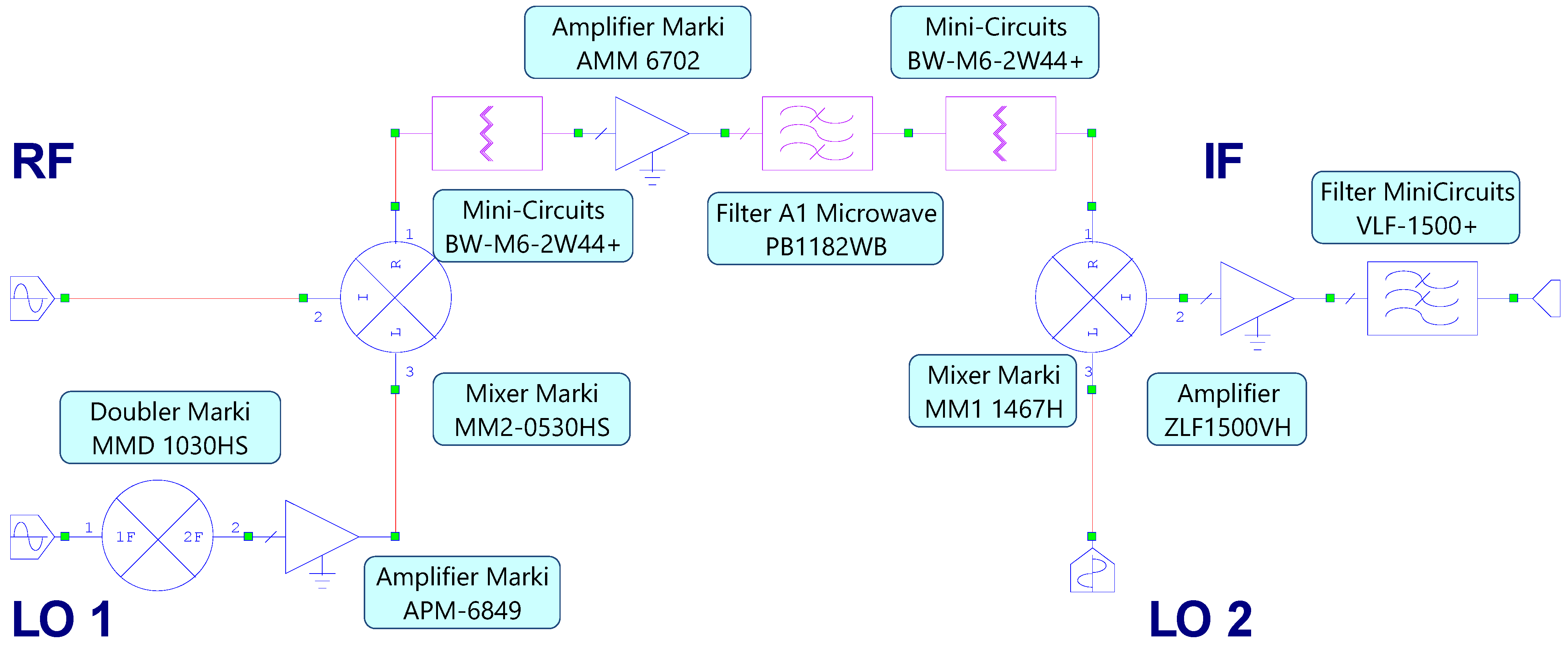
3. Receiver Design, Simulation and Components Characterization
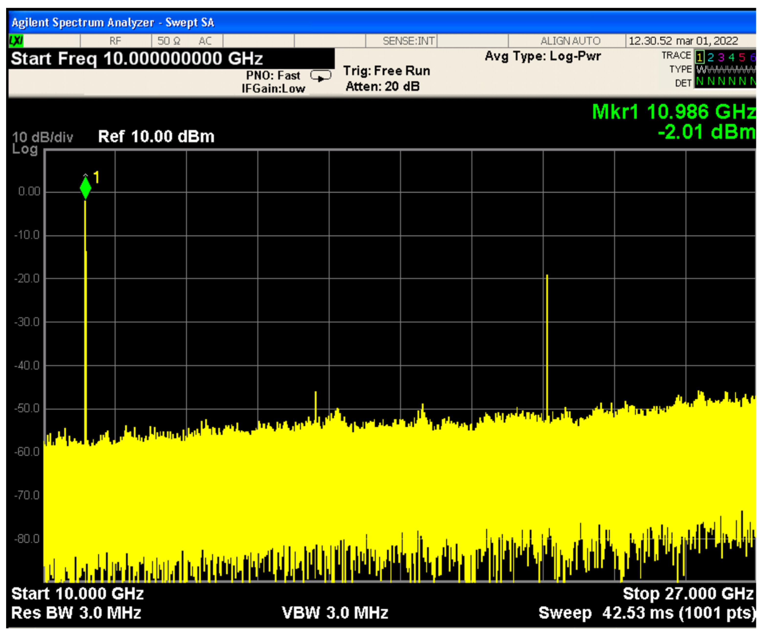
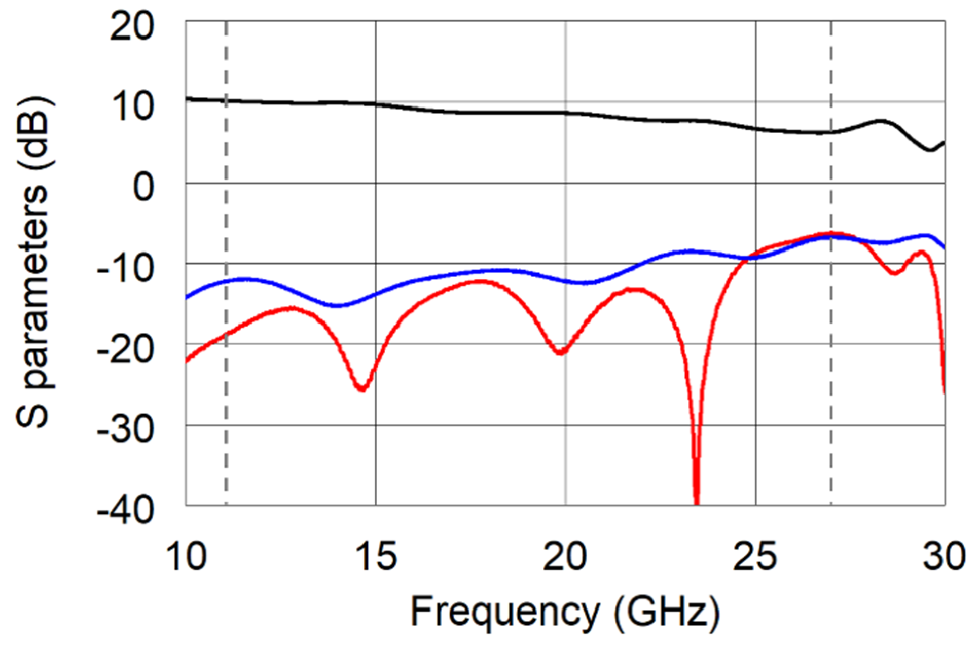
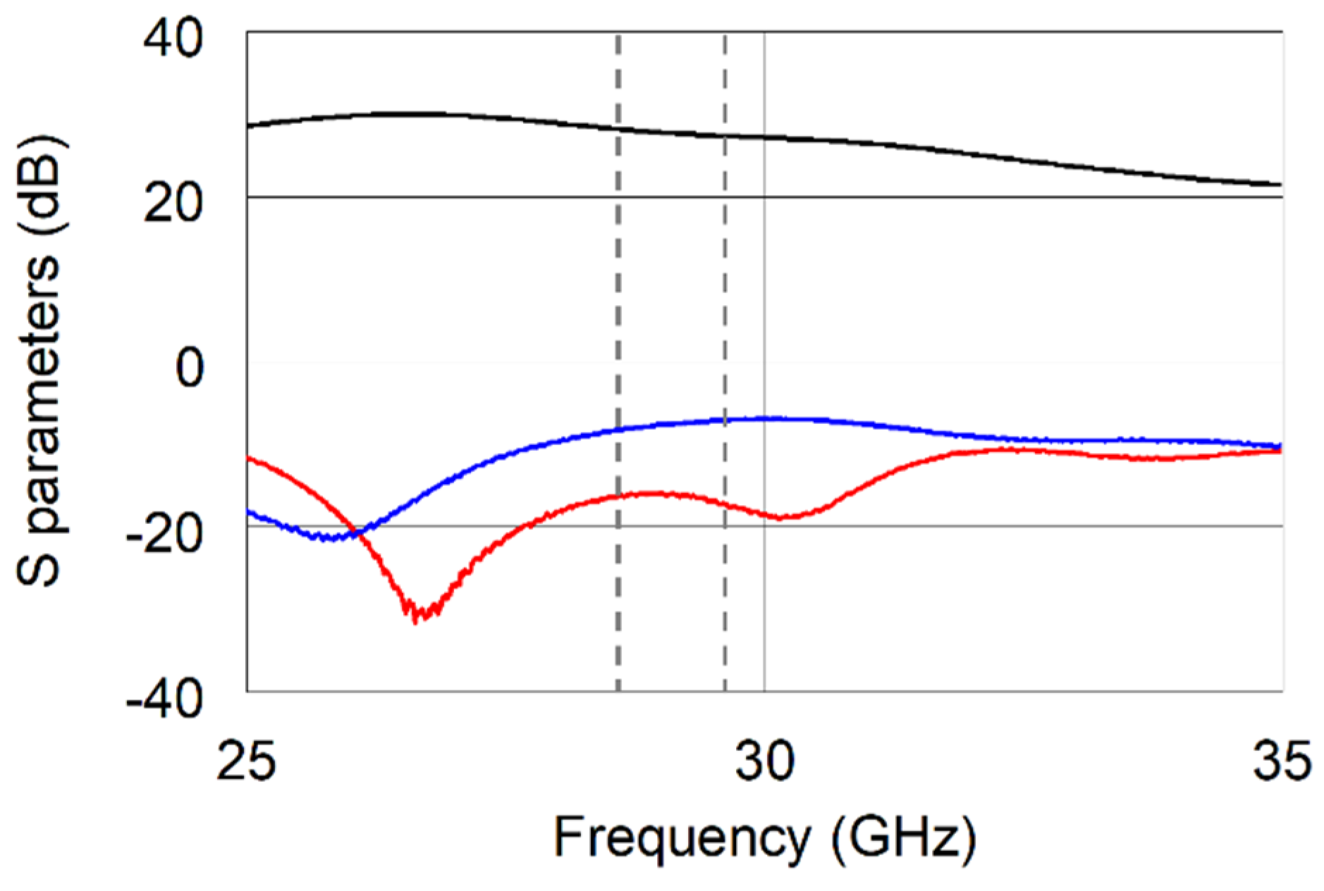
4. Receiver Performance
5. Conclusions
Author Contributions
Funding
Institutional Review Board Statement
Informed Consent Statement
Data Availability Statement
Conflicts of Interest
References
- Bouwmeester, J.; Guo, J. Survey of worldwide pico- and nanosatellite missions, distributions and subsystem technology. Acta Astronaut. 2010, 67, 854–862. [Google Scholar] [CrossRef]
- Nanosatellite & CubeSat Database—Kulu, Erik. Available online: https://www.nanosats.eu/ (accessed on 4 July 2022).
- Liu, S.; Theoharis, P.I.; Raad, R.; Tubbal, F.; Theoharis, A.; Iranmanesh, S.; Abulgasem, S.; Khan, M.U.A.; Matekovits, L. A Survey on CubeSat Missions and Their Antenna Designs. Electronics 2022, 11, 2021. [Google Scholar] [CrossRef]
- Seman, L.O.; Ribeiro, B.F.; Rigo, C.A.; Filho, E.M.; Camponogara, E.; Leonardi, R.; Bezerra, E.A. An Energy-Aware Task Scheduling for Quality-of-Service Assurance in Constellations of Nanosatellites. Sensors 2022, 22, 3715. [Google Scholar] [CrossRef] [PubMed]
- Luglio, M.; Marchese, M.; Patrone, F.; Roseti, C.; Zampognaro, F. Performance Evaluation of a Satellite Communication-Based MEC Architecture for IoT Applications. IEEE Trans. Aerosp. Electron. Syst. 2022, 58, 3775–3785. [Google Scholar] [CrossRef]
- Lepcha, P.; Malmadayalage, T.D.; Örger, N.C.; Purio, M.A.; Duran, F.; Kishimoto, M.; El-Megharbel, H.A.; Cho, M. Assessing the Capacity and Coverage of Satellite IoT for Developing Countries Using a CubeSat. Appl. Sci. 2022, 12, 8623. [Google Scholar] [CrossRef]
- Lin, W.; Dong, Z.; Wang, K.; Wang, D.; Deng, Y.; Liao, Y.; Liu, Y.; Wan, D.; Xu, B.; Wu, G. A Novel Load Balancing Scheme for Satellite IoT Networks Based on Spatial–Temporal Distribution of Users and Advanced Genetic Algorithms. Sensors 2022, 22, 7930. [Google Scholar] [CrossRef]
- Krondorf, M.; Bittner, S.; Plettemeier, D.; Knopp, A.; Wikelski, M. ICARUS—Very Low Power Satellite-Based IoT. Sensors 2022, 22, 6329. [Google Scholar] [CrossRef]
- Fernandez, L.; Sobrino, M.; Ruiz-de-Azua, J.A.; Calveras, A.; Camps, A. Design of a Deployable Helix Antenna at L-Band for a 1-Unit CubeSat: From Theoretical Analysis to Flight Model Results. Sensors 2022, 22, 3633. [Google Scholar] [CrossRef]
- Nakayama, D.; Yamauchi, T.; Masui, H.; Kim, S.; Toyoda, K.; Malmadayalage, T.L.D.; Cho, M.; the BIRDS-4 Project Team. On-Orbit Experimental Result of a Non-Deployable 430-MHz-Band Antenna Using a 1U CubeSat Structure. Electronics 2022, 11, 1163. [Google Scholar] [CrossRef]
- El Bakkali, M.; El Bekkali, M.; Gaba, G.S.; Guerrero, J.M.; Kansal, L.; Masud, M. Fully Integrated High Gain S-Band Triangular Slot Antenna for CubeSat Communications. Electronics 2021, 10, 156. [Google Scholar] [CrossRef]
- Abulgasem, S.; Tubbal, F.; Raad, R.; Theoharis, P.I.; Liu, S.; Ali Khan, M.U. A Wideband Metal-Only Patch Antenna for CubeSat. Electronics 2021, 10, 50. [Google Scholar] [CrossRef]
- Martinez-de-Rioja, E.; Martinez-de-Rioja, D.; López-Sáez, R.; Linares, I.; Encinar, J.A. High-Efficiency Polarizer Reflectarray Antennas for Data Transmission Links from a CubeSat. Electronics 2021, 10, 1802. [Google Scholar] [CrossRef]
- Kovář, P.; Puričer, P.; Kovářová, K. Study of the Two-Line Element Accuracy by 1U CubeSat with a GPS Receiver. Sensors 2022, 22, 2902. [Google Scholar] [CrossRef] [PubMed]
- Finance, A.; Dufour, C.; Boutéraon, T.; Sarkissian, A.; Mangin, A.; Keckhut, P.; Meftah, M. In-Orbit Attitude Determination of the UVSQ-SAT CubeSat Using TRIAD and MEKF Methods. Sensors 2021, 21, 7361. [Google Scholar] [CrossRef]
- Lelekov, A. Estimation of the CubeSat’s Available Energy for Free-Orientation Scenario. IEEE Trans. Aerosp. Electron. Syst. 2021, 36, 6–14. [Google Scholar] [CrossRef]
- Edpuganti, A.; Khadkikar, V.; Moursi, M.S.E.; Zeineldin, H. A Novel Multiport Converter Interface for Solar Panels of CubeSat. IEEE Trans. Power Electron. 2022, 37, 629–643. [Google Scholar] [CrossRef]
- Morishita, Y.; Hanssen, R.F. Temporal decorrelation in L-, C-, and X-band satellite radar interferometry for pasture on drained peat soils. IEEE Trans. Geosci. Remote Sens. 2015, 53, 1096–1104. [Google Scholar] [CrossRef]
- Tings, B.; Pleskachevsky, A.; Velotto, D.; Jacobsen, S. Extension of ship wake detectability model for non-linear influences of parameters using satellite based X-band synthetic aperture radar. Remote Sens. 2019, 11, 563. [Google Scholar] [CrossRef] [Green Version]
- Cardillo, E.; Li, C.; Caddemi, A. Heating, ventilation, and air conditioning control by range-doppler and micro-Doppler radar sensor. In Proceedings of the 18th European Radar Conference (EuRAD), London, UK, 5–7 April 2022; pp. 21–24. [Google Scholar] [CrossRef]
- Cardillo, E.; Caddemi, A. Automotive Anti-Abandon Systems: A Millimeter-Wave Radar Sensor for the Detection of Child Presence. In Proceedings of the 14th International Conference on Advanced Technologies, Systems and Services in Telecommunications (TELSIKS), Nis, Serbia, 23–25 October 2019; pp. 94–97. [Google Scholar] [CrossRef]
- Cardillo, E.; Cananzi, R.; Vita, P.; Caddemi, A. Dual-Conversion Microwave Down Converter for Nanosatellite Electronic Warfare Systems. Appl. Sci. 2022, 12, 1524. [Google Scholar] [CrossRef]
- Caddemi, A.; Cardillo, E.; Crupi, G. Light activation of noise at microwave frequencies: A study on scaled gallium arsenide HEMT’s. IET Circuits Devices Syst. 2018, 12, 242–248. [Google Scholar] [CrossRef]
- Uzun, A.; Ghani, F.A.; Ahmadi Najafabadi, A.M.; Yenigün, H.; Tekin, İ. Indoor Positioning System Based on Global Positioning System Signals with Down- and Up-Converters in 433 MHz ISM Band. Sensors 2021, 21, 4338. [Google Scholar] [CrossRef]
- Abdullah, H.H.; Elboushi, A.; Gohar, A.E.; Abdallah, E.A. An Improved S-Band CubeSat Communication Subsystem Design and Implementation. IEEE Access 2021, 9, 45123–45136. [Google Scholar] [CrossRef]
- Lovascio, A.; D’Orazio, A.; Centonze, V. Characterization of a COTS-Based RF Receiver for Cubesat Applications. Sensors 2020, 20, 776. [Google Scholar] [CrossRef] [Green Version]
- Bhavsar, M.L.; Kumar, P.; Chaturvedi, I.; Srivastava, P.; Singh, D.K.; Bhattacharya, A. LTCC based multi chip modules at C-band and Ka-band for satellite payloads. In Proceedings of the IEEE MTT-S International Microwave and RF Conference, Ahmedabad, India, 11–13 December 2017. [Google Scholar]
- Caddemi, A.; Cardillo, E.; Patanè, S.; Triolo, C. An accurate experimental investigation of an optical sensing microwave amplifier. IEEE Sens. J. 2018, 18, 9214–9221. [Google Scholar] [CrossRef]
- Caddemi, A.; Cardillo, E.; Crupi, G. Comparative analysis of microwave low-noise amplifiers under laser illumination. Microw. Opt. Technol. Lett. 2021, 58, 2437–2443. [Google Scholar] [CrossRef]
- Giggenbach, D. Free-Space Optical Data Receivers with Avalanche Detectors for Satellite Downlinks Regarding Background Light. Sensors 2022, 22, 6773. [Google Scholar] [CrossRef]
- Chen, Q.; Wang, Z.; Pedersen, G.F.; Shen, M. Joint Satellite-Transmitter and Ground-Receiver Digital Pre-Distortion for Active Phased Arrays in LEO Satellite Communications. Remote Sens. 2022, 14, 4319. [Google Scholar] [CrossRef]
- Zou, L.; Dempster, A.G. Multiband Quadrature Bandpass Sampling. IEEE Trans. Aerosp. Electron. Syst. 2022, 58, 2083–2092. [Google Scholar] [CrossRef]


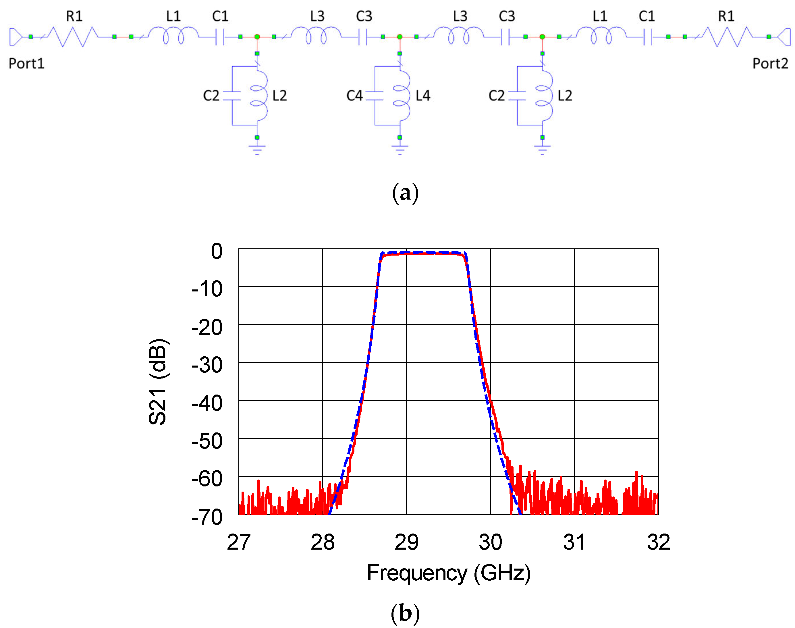
| Element Type | Element ID | Value |
|---|---|---|
| Resistor | R1 | 5 Ω |
| Inductor | L1 | 10.92 nH |
| Inductor | L2 | 6.77 pH |
| Inductor | L3 | 18.11 nH |
| Inductor | L4 | 6.22 pH |
| Capacitor | C1 | 2.72 fF |
| Capacitor | C2 | 4.39 pF |
| Capacitor | C3 | 1.64 fF |
| Capacitor | C4 | 4.78 pF |
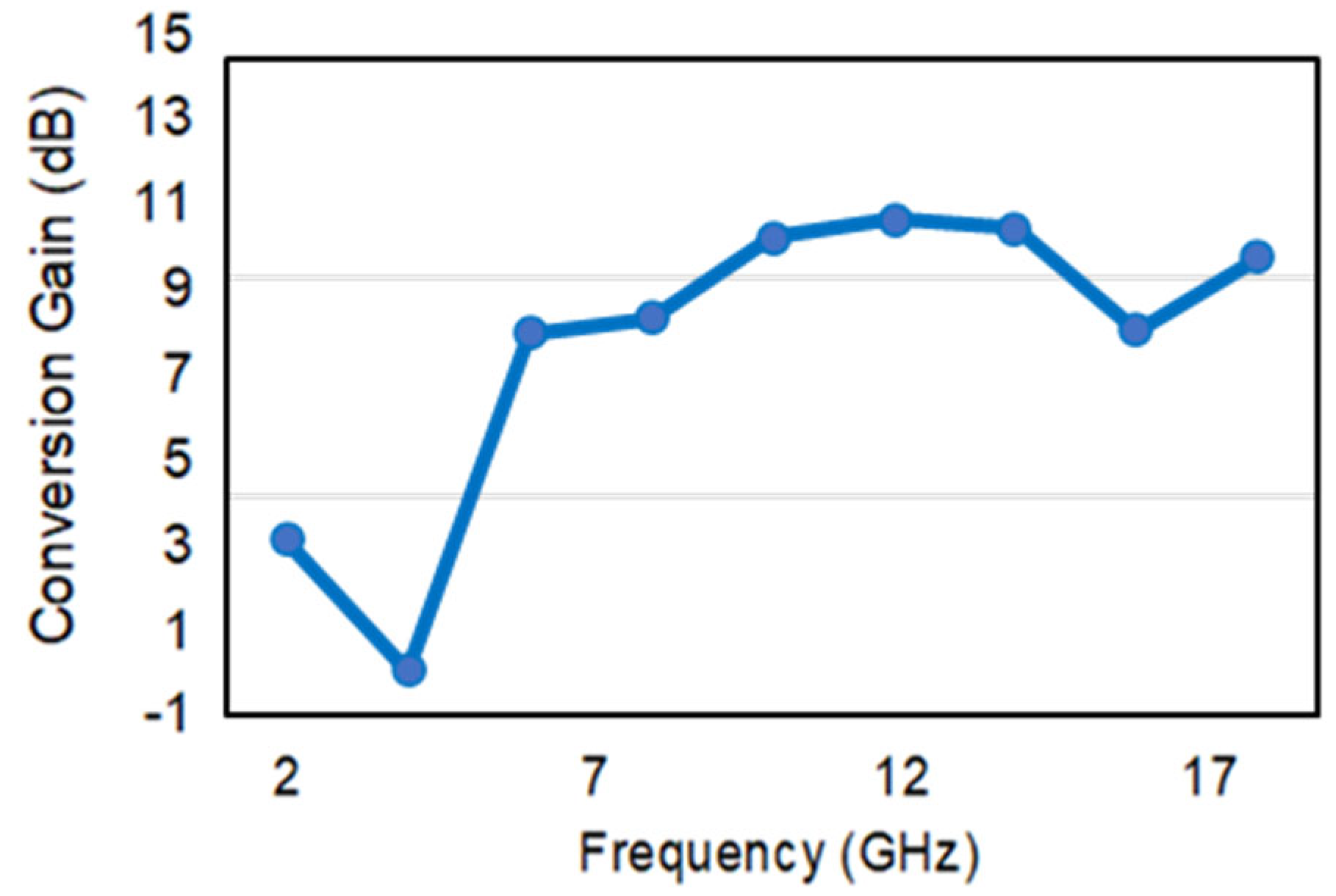
| Frequency (GHz) | 2–18 |
| Average CG (dB) | 8.4 |
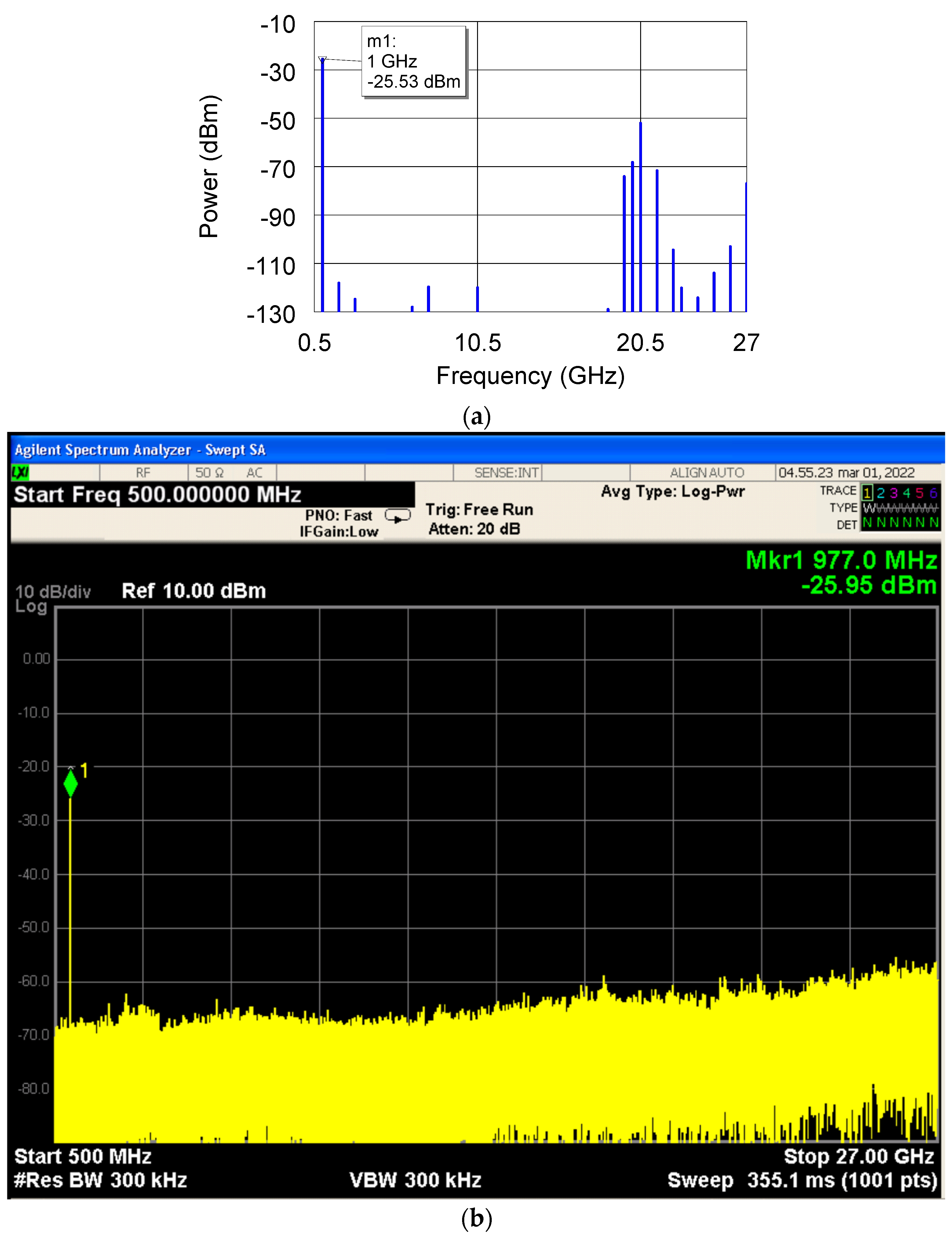
| Minimum spurious suppression level (dBc) | −45 |
| Microwave section power consumption (W) | 1 |
Publisher’s Note: MDPI stays neutral with regard to jurisdictional claims in published maps and institutional affiliations. |
© 2022 by the authors. Licensee MDPI, Basel, Switzerland. This article is an open access article distributed under the terms and conditions of the Creative Commons Attribution (CC BY) license (https://creativecommons.org/licenses/by/4.0/).
Share and Cite
Cardillo, E.; Cananzi, R.; Vita, P. Wideband Versatile Receiver for CubeSat Microwave Front-Ends. Sensors 2022, 22, 9004. https://doi.org/10.3390/s22229004
Cardillo E, Cananzi R, Vita P. Wideband Versatile Receiver for CubeSat Microwave Front-Ends. Sensors. 2022; 22(22):9004. https://doi.org/10.3390/s22229004
Chicago/Turabian StyleCardillo, Emanuele, Renato Cananzi, and Paolo Vita. 2022. "Wideband Versatile Receiver for CubeSat Microwave Front-Ends" Sensors 22, no. 22: 9004. https://doi.org/10.3390/s22229004