1. Introduction
6G will provide all-around wireless coverage and interconnection of all things [
1]. Intelligent Reflecting Surface (IRS) is one of the key technologies for 6G, which has the advantages of low energy consumption and simple deployment [
2,
3,
4]. Specifically, IRS is a planar surface comprising a large number of reconfigurable passive electrical components that can adjust the phase shift of incident signal according to different channel conditions, leading to more reliable communication links, greater transmission capacity and higher spectral and energy efficiency [
5,
6].
Owing to these advantages, IRSs have attracted intensive attention and have been applied in several scenarios, including IRS-assisted integrated satellite unmanned aerial vehicle (UAV) terrestrial networks [
7], IRS-assisted anti-jamming communications [
8,
9], cell-free massive multiple-input multiple-output (MIMO) system with IRS assistance [
10] and IRS-assisted secure integrated terrestrial-aerial networks [
11]. However, the deployment of IRS in different scenarios can greatly affect the performance and coverage of the system. To further improve the spectral efficiency and coverage of the system, how to jointly design beamforming according to the deployment scheme is a challenge to be solved.
Recently, most beamforming research is generally performed in single IRS-assisted systems [
12,
13]. In [
12], the authors studied a single IRS-assisted multi-user downlink transmissions model under perfect and imperfect channel state information (CSI), respectively, and proposed a block coordinate descent (BCD) method to maximize the weighted sum rate (WSR). Furthermore, in [
13], in the process of jointly active and passive vector optimization design, a low-complexity beamforming algorithm based on closed-form expressions of optimization variables was proposed. The aforementioned works mainly studied the single IRS-assisted models, which are not flexible, resulting in low coverage of wireless communication systems.
To further obtain higher spatial multiplexing gain and enhance coverage, the authors extended the scenario to distributed IRSs in [
14], which broke the rank-one constraint of the base station (BS) to the IRS channel and developed a higher-rank channel, and they proposed an alternating optimization (AO) method to jointly design active and passive beamforming. Then, in [
15], a hybrid active and passive wireless network with large-scale deployment of BSs and distributed IRSs was investigated to achieve network capacity growth by adjusting the optimal IRS to the BS density ratio.
In both [
14,
15], the distributed IRSs independently serve the related users in the local coverage area without considering the cooperation power between IRSs, which simplifies the beamforming design scheme. However, there will be signal reflections between IRSs in practice, and the role in a small range of environments is clear. The above passive beamforming scheme is no longer optimal when considering the inter-IRS reflection channel. Therefore, a new cooperative beamforming design is required.
To solve the signal interaction problem between cooperative IRSs, some recent works have investigated cooperative IRSs beamforming. In [
16], the authors made a preliminary attempt to achieve far more than a conventional single IRS system by designing the passive beamforming of two cooperative IRSs; however, they only investigated the cooperative power gain of the double-reflection link without considering the spatial multiplexing gain brought by the two single-reflection links.
Moreover, in [
17], the capacity maximization problem of MIMO system with double-IRS assistance was studied by jointly optimizing the transmit covariance matrix and the passive beamforming matrix under the line-of-sight (LoS) channel characteristics. However, the LoS path considered in [
17] is an ideal model, and the application scenario is limited due to the failure to consider small-scale fading.
Then, the paper [
18] considered double IRS-assisted the uplink communication system under the general channel conditions and adopted semidefinite relaxation (SDR) and the bisection method to effectively solve the problem of maximizing the minimum signal-to-interference-plus-noise ratio (SINR). However, the SDR method not only has a large number of iterations but also can only obtain approximate solutions because of Gaussian randomization. The results suggest that double-IRS model has a huge potential for improving spectral efficiency.
Inspired by the above works, we aim to maximize the WSR of the cooperative IRS-assisted millimeter wave (mmWave) downlink communication and propose a joint beamforming design scheme. The main contributions of this paper are as follows:
First, for multivariate coupled non-convex optimization problems, we implement the decoupling of optimization variables based on fractional programming (FP) and convert the original problem equivalently into four subproblems in this paper.
Next, we design an extended AO algorithm to solve the joint beamforming design problem under continuous phase shift to maximize the WSR of the system. In terms of the active transmission vector, quadratic transform (QT) is adopted to reconstruct the optimization problem and obtain a closed-form expression for the optimization variable. Regarding reflection vector optimization, the twice stochastic successive convex approximations (SCA) technique is adopted to find the optimal step size separately to achieve a joint optimization of the passive phase shifts.
In addition, we extend the passive beamforming scheme to the case of discrete phase shifts of the IRS. The simulation results show that, for both continuous and discrete phase shifts, the proposed beamforming scheme of the double IRS-assisted system outperforms the conventional single IRS-assisted system.
The remainder of this paper is structured as follows. The double IRS-assisted system model and problem formulation are introduced in
Section 2. In
Section 3, we present the detailed derivations of the proposed low-complexity AO algorithm. The simulation results are analyzed in
Section 4 to demonstrate the effectiveness of the proposed algorithm. Finally, we give our conclusions in
Section 5.
The notations used in this paper are listed as follows. denotes statistical expectation. denotes the circularly symmetric complex Gaussian (CSCG) distribution with mean and variance . denotes the minimum between two real numbers and . ⊗ denotes the Kronecker product. Superscripts , and denote the conjugate, the transpose and the conjugate transpose of , respectively. denotes the space of complex-valued matrices. For any vector , is the i-th element, and denote the Euclidean norm and the Frobenius norm, respectively. Furthermore, denotes the diagonal matrix of vector . represents the identity matrix. For any complex variable , denotes the absolute value of a complex variable , and represents the real part.
2. System Model and Problem Formulation
In this section, we present the transmission and channel model of a double IRS-assisted mmWave communication system and propose the problem formulation.
2.1. Transmission Model
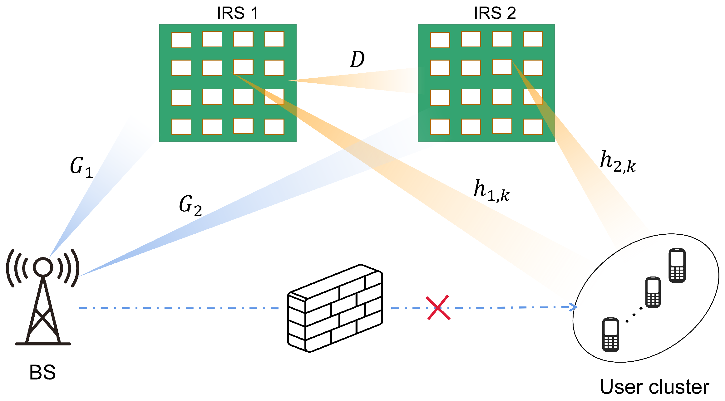
As shown in
Figure 1, we consider a double IRS-assisted multi-user multiple-input single-output (MISO) downlink communication system, which consists of one BS equipped with
M antennas and a cluster of
K sigle-antenna users. Two cooperative IRSs are deployed in the network to provide high-quality transmission links. Considering the impact of path loss on the cooperative IRSs model, a realistic deployment scenario is developed in which IRS 1 and IRS 2 are placed near the user cluster and BS, respectively, to minimize the path loss.
To better represent the enhanced effect of IRS, we also consider that the direct links between the user equipment (UE) and the BS are blocked. Additionally, two IRSs are properly deployed to construct a LoS path from the IRSs to the BS and the users, so that the BS can effectively serve the users through the reflection link created by them.
To facilitate comparison with the single IRS deployment scheme, we assume that the total reflection elements of the single IRS and cooperative IRSs model consist of N elements, with IRS 1 and IRS 2 consisting of and reflection elements, respectively, with . The corresponding phase shift matrix of IRS is denoted as , in which denotes the equivalent reflection coefficient.
Then, the continuous phase feasible set can be expressed as . In this case, the reflection amplitude of all elements is set to 1 to maximize the signal power and thus . The feasible set corresponding to the discrete phase is given by , where B is the phase resolution in the number of bits.
Each IRS consists of an arbitrary number of adjoining reflection elements, which, on the one hand, produce the same phase shift for the incident signal, bringing a high aperture gain, and on the other hand, their near-passive feature significantly reduces the cost of channel estimation and reflection optimization [
19,
20].
Let
,
,
,
and
denote the equivalent channels for
,
,
,
,
, respectively, where
. Under the above conditions, the channels from
to user
k via a double-reflection link, and two single reflection links can be expressed as
To highlight the fundamental performance gain of the double-IRS cooperative system, we assume that the CSI of all the above channels can be obtained accurately. In addition, we assume that all the channels are the quasi-static flat-fading channel model, which remains approximately constant within each channel coherence interval.
We set
denote the transmitted signal from the BS to user
k with
,
. Then, the transmitted signals for all users can be defined as
where
is the corresponding transmit beamforming vector. During downlink data transmission, the signal received at user
k can be expressed as
where
. The
k-th user is subject to interference from other users; thus, the corresponding SINR can be designated as
In addition, the transmit power constraint at BS is modeled as
where
represents the maximum transmit power, and
denotes the overall beamforming matrix at the BS.
2.2. Channel Model
Due to the sparse scattering characteristics of mmWave channels, this paper uses the 3D Saleh–Valenzuela channel model [
21,
22], where the BS is equipped with a uniform linear array (ULA), and the two IRSs are uniform planar arrays (UPA). Then,
and
can be expressed as
where
and
represent the number of non-line-of-sight (NLoS) paths,
denotes the LoS path, and
is the complex gain of the
ℓ-th path. The mmWave channels typically contain only a small number of major multipath components. Here, the azimuth and elevation angles are denoted by
and
,
denotes the array steering vector of IRS, and the array steering vector of the BS is expressed as
where
is the signal wavelength, and
denotes the spacing between the antennas. It is assumed that each IRS unit has
elements horizontally and
elements vertically. Then, the array steering vector of IRS is expressed as
where
and
are defined in the same manner as
.
Typically, because the IRS is widely distributed in hotspot locations, the probability of LoS paths is high. The IRS-user channel model ignores the transmit power of more than two reflections due to suffering from severe path loss and only considers the LoS path [
9]. Thus, the channel between the IRS and the
k-th user is modeled by
where the
and
are the transmit and receive antenna gains,
is the channel gain.
2.3. Proposed Problem Formulation
In this paper, we aim to maximize the WSR at the downlink transmission by jointly optimizing the active and the cooperative passive vector, subject to maximum transmit power and phase shift constraints. The optimization problem is formulated as
where the weight
represents the priority of the
k-th user. Since the non-convexity and non-linearity of problem
, it is difficult to solve it optimally. In addition, the optimization variables
,
and
are deeply coupled; therefore, finding the global optimal solution is a challenge.
Problem
is to maximize a sum-of-log-of-ratio objective, which is a typical FP problem [
23]. To solve the multi-variate coupled problem, we first transform
into a much low-complex problem by introducing optimization variable. It can be rewritten as
where
The parameters
are the auxiliary variables introduced for each user by the Lagrangian dual transform [
24], and then
is the auxiliary vector.
For ease of reading,
Table 1 summarizes the main symbol notations used in this paper and their physical meanings.
3. Joint Active and Passive Beamforming
The above-mentioned original problem is transformed into an optimization problem containing , , and . To solve the problem efficiently, we first, decouple the problem into four disjoint optimization subproblems. Then, we propose an extended low-complecity AO algorithm. In other words, we optimize the beamforming of the transmission vector and the cooperative reflection vector in an alternating iterative form. In addition, we choose the traditional single IRS-assisted scheme as the benchmark for performance analysis comparison. The details on how to optimize the variables alternately are given as follows.
First, we aim to find the optimal closed-form expression for with given , and . Specifically, when fixed , and , the problem can be viewed as an unconstrained optimization problem for .
Proposition 1. When , and are fixed, the optimal can be obtained as Proof. Taking the partial derivative of
with respect to
yields
Let , we can obtain that makes the objective function maximized. As when , when . □
Based on the obtained closed-form expression about , we propose solutions for the active vector and the cooperative passive vector and in the next two subsections, respectively.
3.1. Active Beamforming Scheme
When
is fixed, we can formulate a new optimization problem with respect to the active vector
and the cooperative passive vector
and
, which can be rewritten as
where
, and the
can be rewritten as
when
,
and
are fixed, we ignore irrelevant variables and substitute (17) into (16), the problem
can be formulated as
The above problem is a multi-ratio sum problem with respect to
, and it can be reformulated as a biconvex optimization problem by QT [
24]. Thus, the objective function can be reformulated as
where
are the introduced complex auxiliary variables, and
is the auxiliary vector. Problem
is therefore equated to solving the biconvex problem with respect to
and
as follows
Proposition 2. When is fixed, the optimal can be updated by Then, the optimal beamforming vector is obtained by the Lagrange multiplier method, which can be expressed as Proof. When
is fixed, taking the partial derivative of
with respect to
yields
Let
, then the above Equation (
21) is obtained. When
is fixed, considering the maximum transmit power constraint, the Lagrangian function of
can be obtained as
where
is the dual variable introduced by considering about the power constraint and the partial derivative of
with respect to
as follows
let
, the above expression (22) can be obtained. □
In general, the optimal
can be obtained using the bisection method, and a large number of iterations of searching is generally required to obtain a high-accurate
. However, to avoid operating the matrix inverse too many times, we take the following update form of
[
12].
where
, the gradient is expressed as
where
is the extrapolation point,
is the value of the last alternate iteration,
is the value of
before it was updated to
, and
denotes the extrapolation weight. The updated expression for
is
Using this linear approximation eliminates the need for a bisection search. We let
represent the value of the previous iteration and
is the value of the current iteration.
is the Lipschitz constant of the gradient function
. Furthermore, the extrapolation weight is taken by
where
is defined as
with initial value 1.
3.2. Passive Beamforming Scheme
When optimizing cooperative reflection vector
, we first, fix
,
and
. Then, by denoting
, we can transform the channel
to be further expressed as
where
and
represent the channel components of the two single-reflection links, respectively.
represents the channel components of the cooperative double-reflection link. Then,
is further expressed as
Then, the sub-optimization problem with respect to
can be transformed to be
where
and
are
with
and
. We further replace
by
with
. Then, we can obtain as follows
where
; however,
is still non-convex. Thus, we further exploit the SCA technique to solve this problem, with the construction of surrogate function referring to [
25]. We use the second order Taylor expansion at
to construct the surrogate function which can be expressed as
where
, and the optimization problem can be expressed as
The expression for the iteration with respect to
is given by
In order to speed up the iteration of the algorithm, a proper search step size
in (39) is needed. Furthermore, we consider optimization problem as follows
To solve problem (
), we construct function as follows
It is known that
is a continuously differentiable function, and the gradient of
is
The step size
in this paper can be determined by the Armijo rule [
26].
where
,
is the largest element in the
and
.
Next, we optimize the reflection vector
of IRS 2, meanwhile the remaining variables are fixed. The problem
can be rewritten as
we construct
and
as follows
where
and
. Following the similar transformations from (36) to (43), we can again obtain the optimal reflection vector
of IRS 2 by determining the appropriate step size based on the Armijo rule.
In the proposed AO algorithm, we transform the original problem into four subproblems, and the beamforming algorithm design accommodated to the cooperative double IRS-assisted model is implemented by iteratively solving the four subproblems. In particular, the solution obtained in each iteration is used as the initial point for the next iteration. The details of the proposed algorithm to achieve WSR maximization are summarized in Algorithm 1.
| Algorithm 1: The AO Algorithm for joint design of active and cooperative passive beamforming. |
1. Initialization: Set feasible values of . Set the threshold value and the maximum mumber of iterations . Iteration . 2. Repeat 3. Update according to (14). 4. Update according to (21). 5. Update according to (28) and (29). 6. Construct and by (34) and (35). 7. Update according to (39). 8. With given , update . 9. Construct and by (45) and (46). 10. Update . 11. With given , update . 12. Set . 13. Until the increase of the WSR value is below the threshold or the interation number i reaches the . 14. Perform the quantized phase projection. |
4. Simulation Results
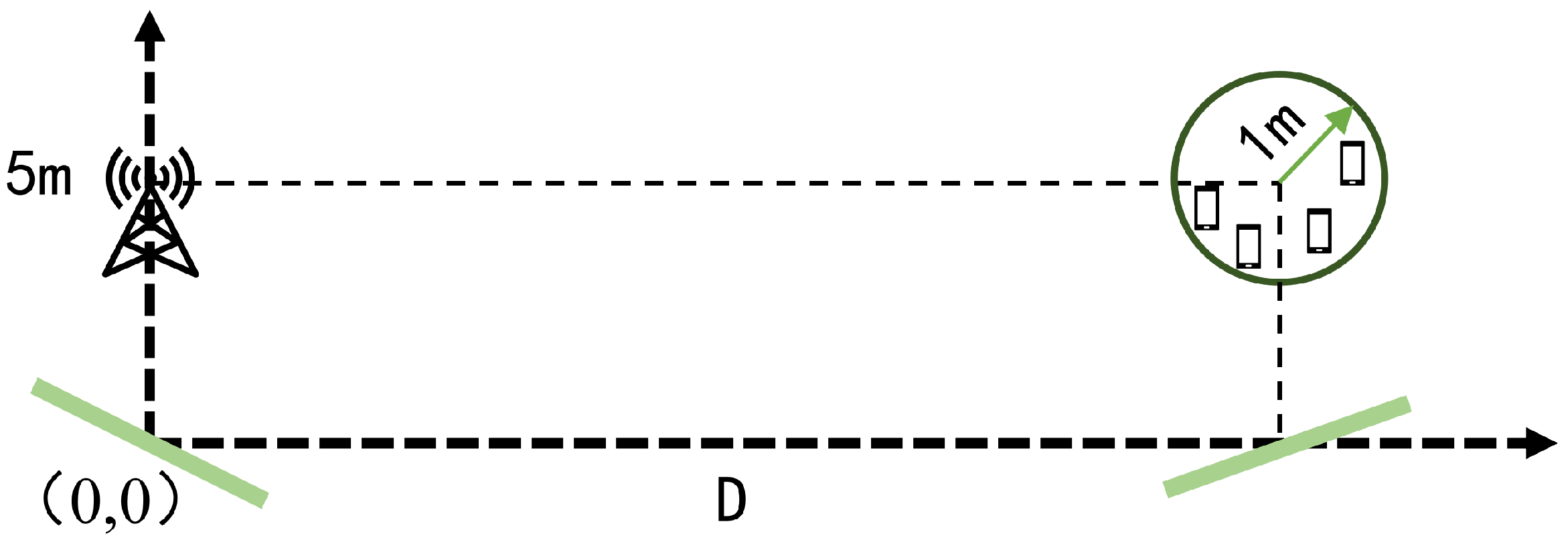
In this section, simulation results are used to examine the performance of the cooperative double IRS-assisted multi-user system and to verify the feasibility of AO algorithm. The considered system is depicted in
Figure 2, in which one BS is equipped with 4 antennas and 4 single-antenna users
randomly distributed in a circle center at
with a radius of 1 m. Since the direct link channel from the BS to the UE is not considered, our weight value is chosen as
.
According to [
21], the channel gain is taken as
where
with
. The channel realizations are produced by setting
,
,
,
,
,
. The BS is located at (0 and 5 m), and two IRSs with the number of elements
are located at
and
, respectively. Furthermore, we consider the transmit power of the BS is set to
, and the number of quantized bits is
.
We focus on the impact of the main system parameters on the WSR, adopting three benchmarks to evaluate the performance of the model and algorithm: (1) cooperative IRS phase randomization, and then
is optimized using the weighted minimum mean square error (WMMSE) [
27] (Random Phase); (2) single IRS scheme near the BS; and (3) single IRS scheme near the UE.
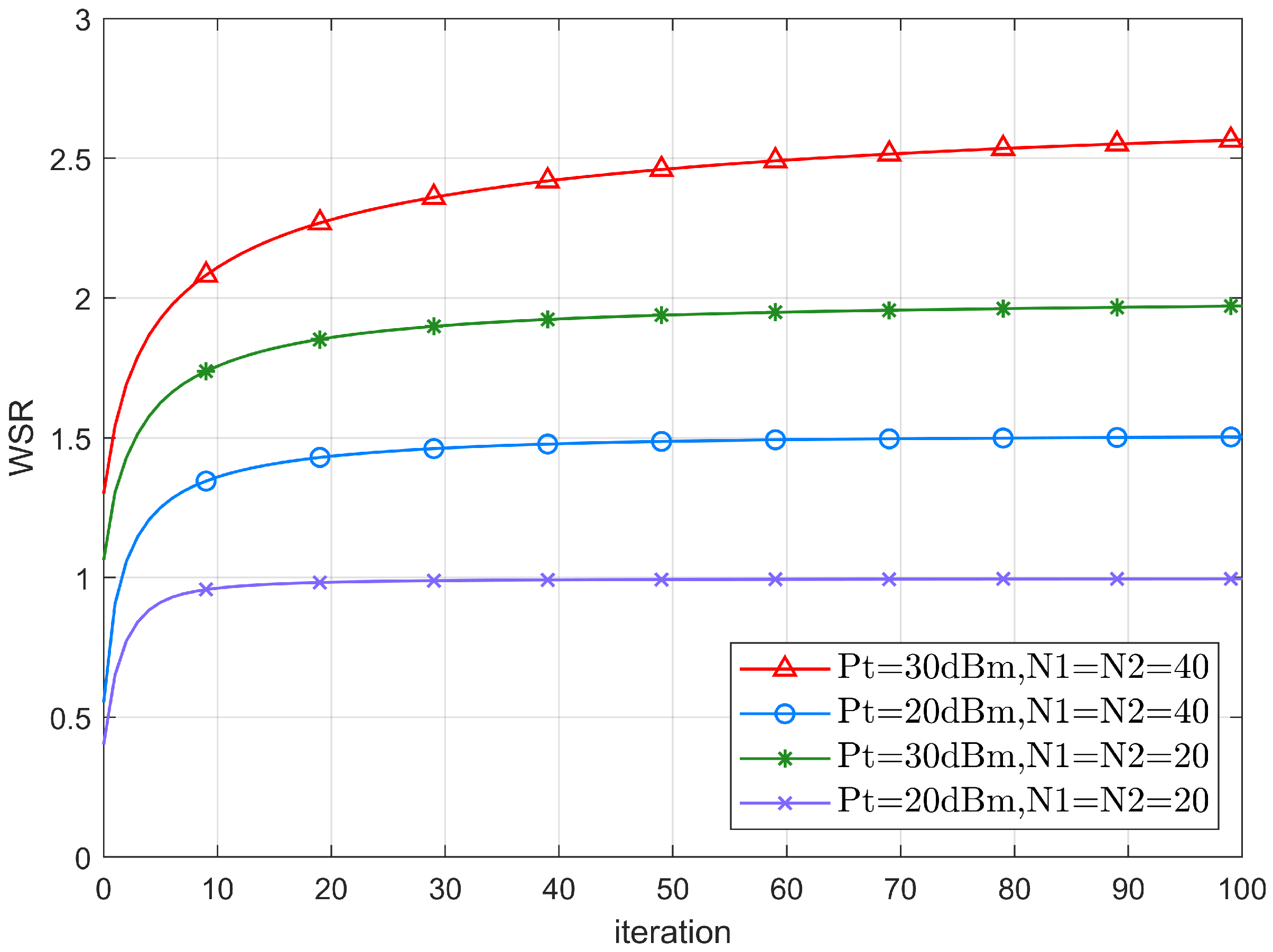
Figure 3 shows the WSR convergence behaviors of the system for different transmit power and the number of IRS reflection elements. It can be seen that for different
and reflection elements, the WSR gradually converges to a smooth level as the number of iterations increases, proving the practicality of the proposed algorithm. In particular, at the transmit power of
, the WSR converges in about 20 iterations when the number of two IRSs reflection elements is 20.
Still, when the number of two IRSs reflection elements is increased to 40, it takes 40 iterations before the WSR converges. This is because as the number of reflection elements gradually increases, the number of variables to be optimized increases, resulting in a decrease in the convergence rate. As the transmit power increases, the SINR increases and better performance of the system is obtained, and thus the number of iteration steps required to achieve a higher convergence value increases accordingly.
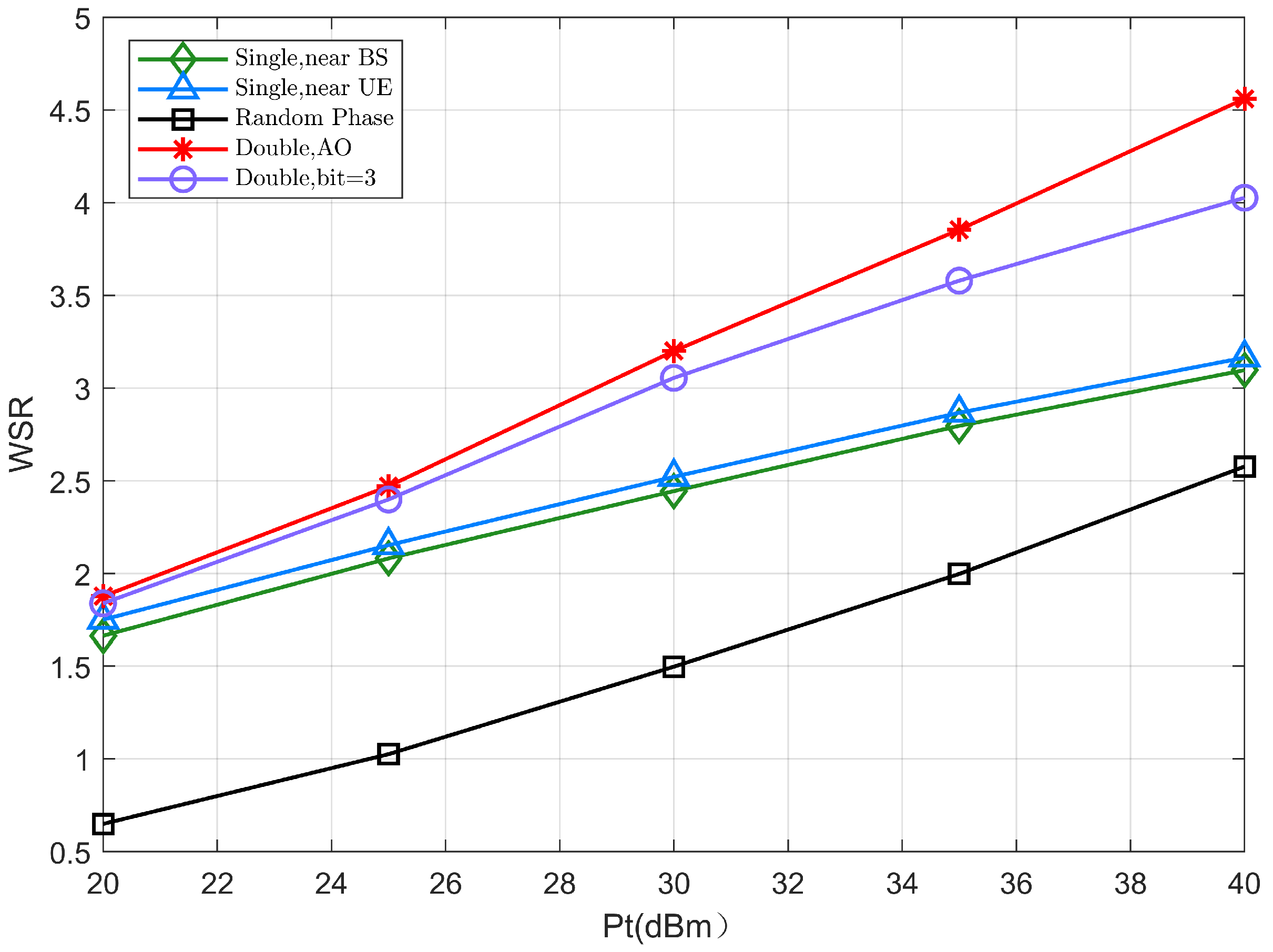
In
Figure 4, we fix the number of reflection elements of the two IRSs to be
, demonstrating the variation in performance of the WSR with varying transmit power
. It can be seen that the double-IRS model shows better performance than the single IRS
model for both continuous and discrete phase shift scenarios. Especially, considering a reference value at
, the joint beamforming based on the double-IRS scheme can achieve about
gain compared to the single IRS scheme.
This is mainly because the cooperative double-IRS system has the spatial multiplexing gain of the two single-reflection links in addition to the cooperative power gain of the double-reflection link, which helps to improve the WSR of the system. In addition, the WSR in the single IRS scheme is not sensitive enough to the transmit power, the cooperative double IRS scheme has an increasingly faster performance improvement in case of the transmit power gradually increases, and the difference between them is more pronounced as the transmit power increases.
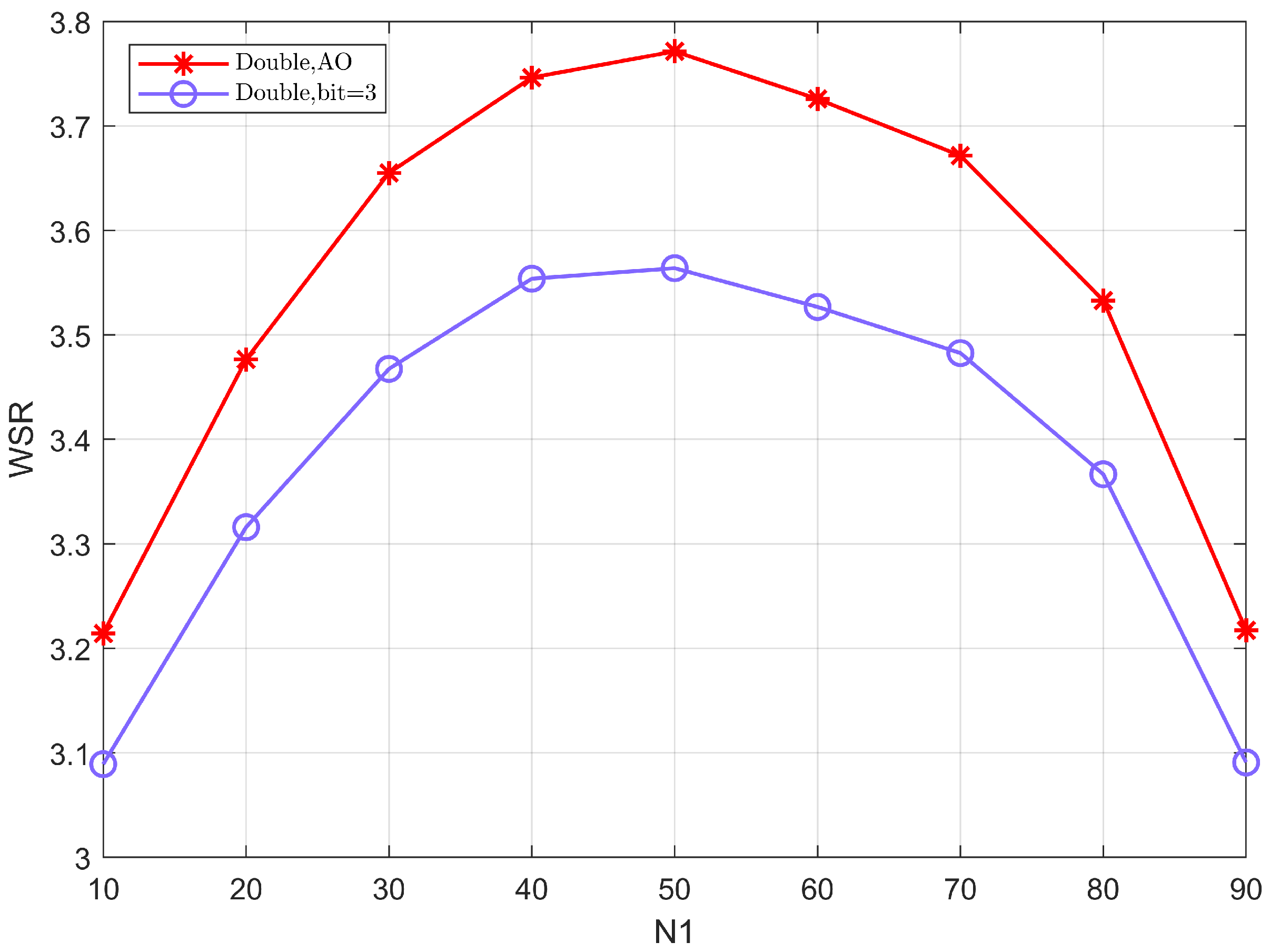
Figure 5 shows the WSR versus the number of the reflection elements
assigned to IRS 1 when other conditions are the same and we fix the total number of elements to be
. From the figure, it can be seen that the value of WSR is greatest when the number of elements of the two cooperative IRSs is equal. This is primarily because reasonably assigned elements can efficiently balance the passive beamforming gain, resulting in improved system performance.
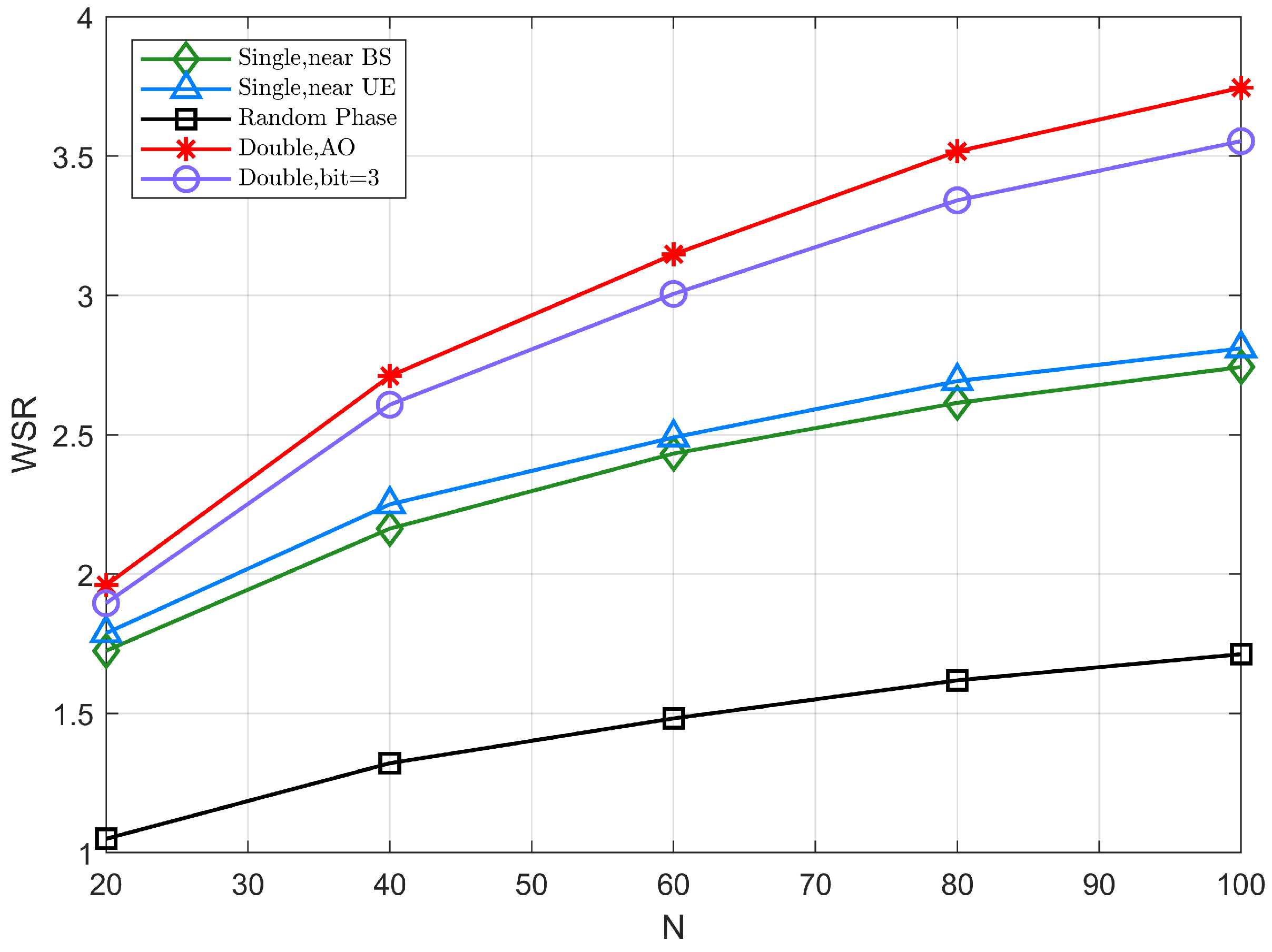
Figure 6 illustrates the WSR of different schemes with respect to the number of reflection elements N when
, where
. The WSR gradually increases with the number of reflection elements in each of the different scenarios, as the increase in the number of reflection elements improves the array gain of the IRS. Among them, the cooperative IRS model significantly improves spectral efficiency than the single IRS model.
Considering a reference value at , the joint beamforming based on the double-IRS scheme can achieve about 3dB gain compared with a single IRS scheme, because the cooperative system obtains better channel rank conditions by adopting the double-IRS deployment. In addition, while the growth of WSR in the single IRS model varies smoothly with the number of reflection elements, the double-IRS model improves its performance at an increasing rate with the increase in the number of reflection elements, consistently maintaining superior system performance. Furthermore, their difference is more obvious as the number of reflection elements increases.
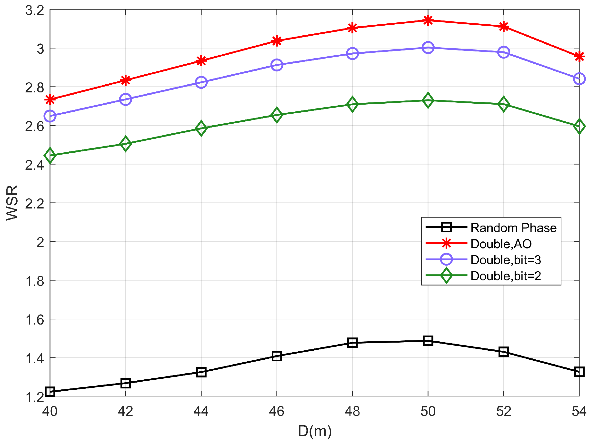
Figure 7 shows the relationship between the WSR of the system as IRS 2 is moved from
to
. D represents the horizontal coordinate of IRS 2 i.e., the horizontal distance between two IRSs. It depicts that when D increases from
to
, the system performance gradually decreases as the path loss of channel D becomes larger. Moreover, the WSR increases as the IRS 2 moves from
to
, indicating that it is not the case that the closer the distance between the two IRSs is the better.
This is because the decrease in the inter-IRS distance decreases the path loss of the channel D; however, along with the change in D, the distance between the user and the IRS 2 also changes. In addition, the reduction of the sum of transmission distances does not necessarily mean that the transmission conditions become better. Therefore, when deploying locations of IRSs, it is necessary to consider not only the factor of path loss, but also the location of the users.
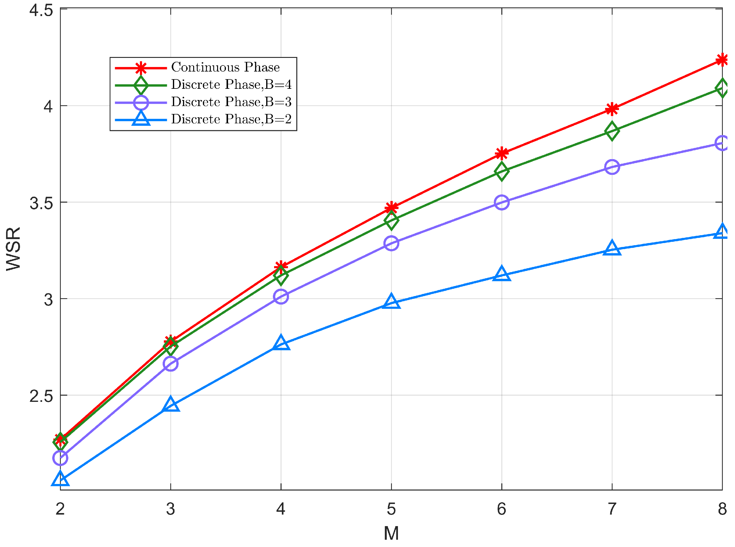
Figure 8 shows the variation of WSR with the number of antennas at the BS for both discrete and continuous schemes. According to the figure, in the discrete phase shift case, the larger the number of quantized bits (B = 4), the closer the system WSR is to the continuous case. This is because the performance loss caused by the rounding process during quantization is smaller at higher bit counts. It also shows that the proposed approach is suitable for discrete phase shifter with a high level of phase shift. However, the implementation difficulty increases as the number of quantized bits increases in practice. Thus, we only need to use a small number of quantized bits (B = 3) to achieve satisfactory system performance.
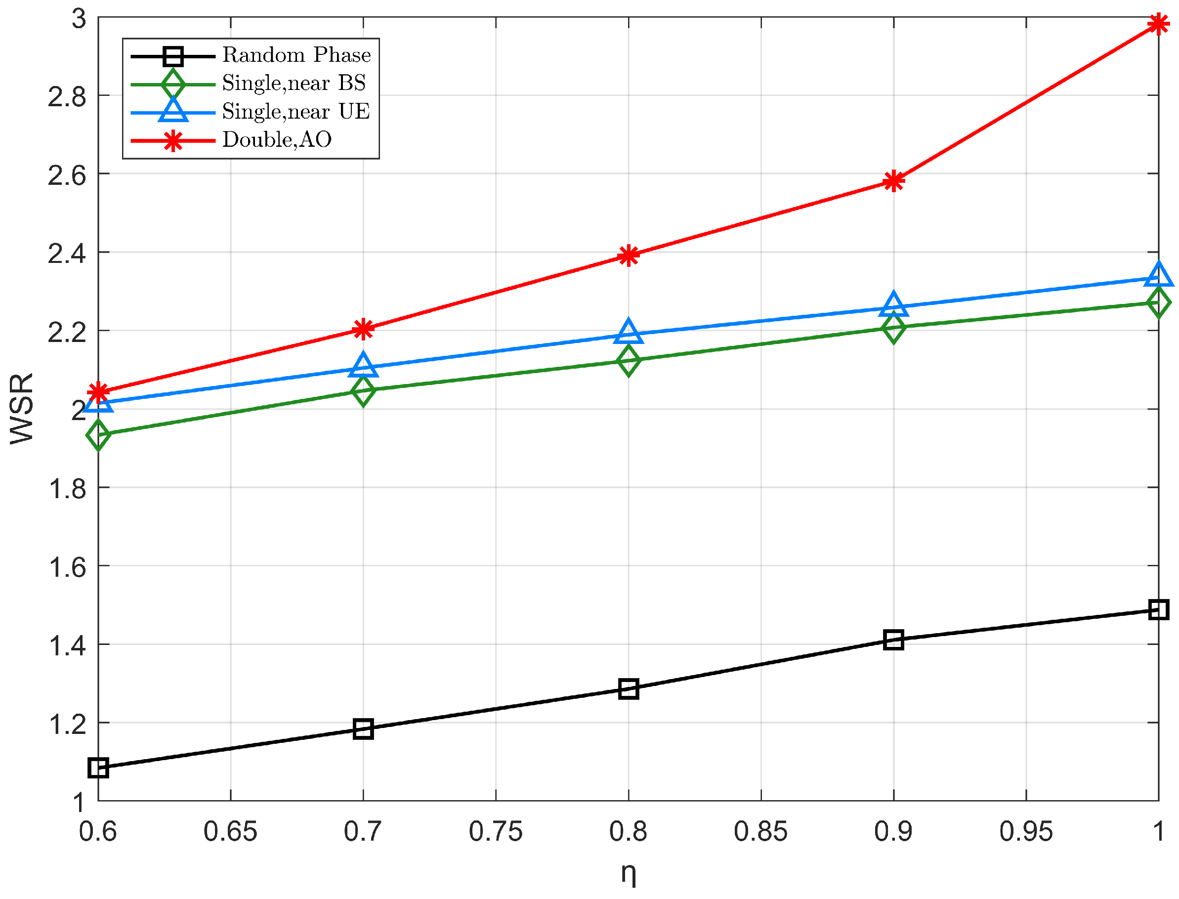
Considering the practical application, there may be power loss at the IRS due to the absorption reflection of the phase shifter of the IRS, which we define as
with
.
Figure 9 investigates the effect of
on the WSR of the system, and as the power loss decreases, the WSR of the system increases significantly. Specifically, the enhancement effect of cooperative IRS scheme is more obvious when
is close to 1. Furthermore, when
increases from 0.6 to 1, the WSR based on the double IRS-assisted scheme achieves about 4 dB gain.


