
Radio Frequency Energy Harvesting Technologies: A Comprehensive Review on Designing, Methodologies, and Potential Applications


 , , and
Abstract
:1. Introduction
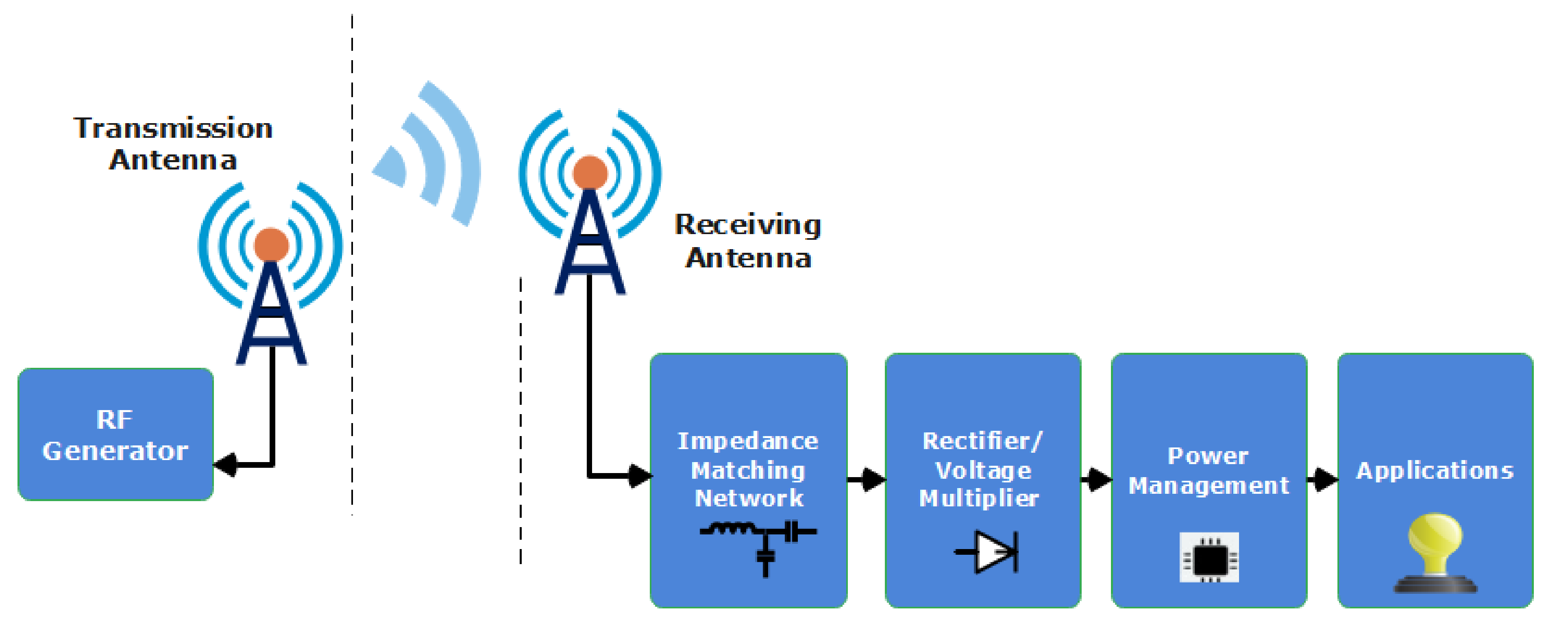
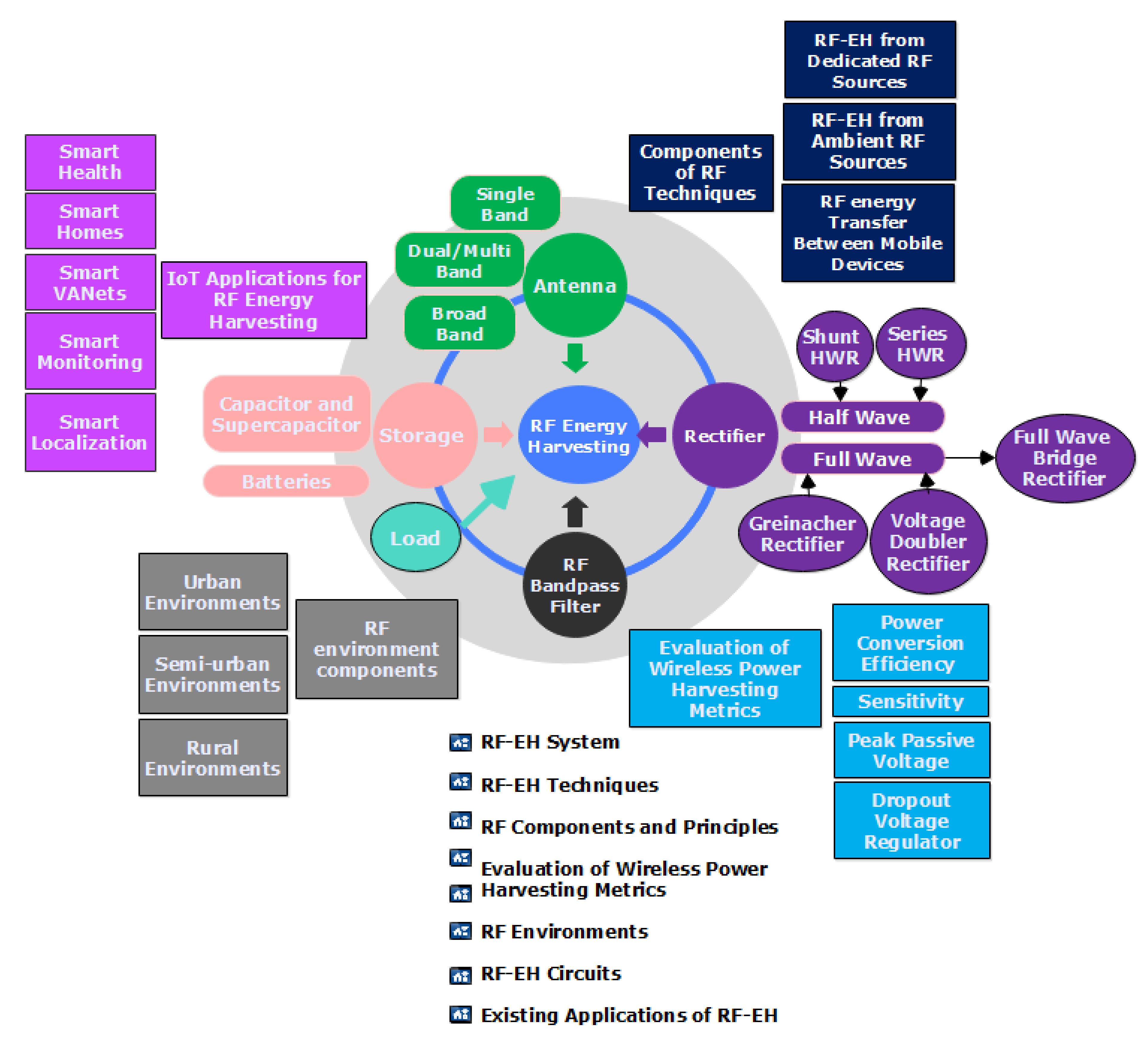
2. RF-EH System
3. RF-EH Techniques
- (a)
- Ability to regulate and provide constant energy transfer over a long distance.
- (b)
- The harvested energy is relatively stable and predictable for long-term performance to the fixed distance in an RF-EHN setup.
- (c)
- The different locations of network nodes exhibit a substantial difference in the RF-RH since the total RF-EH relies on how far the dedicated RF source is from the ambient RF source.
3.1. RF-EH from Dedicated RF Sources
3.2. RF-EH from Ambient RF Sources
- Static sources, even though they are stable-power transmitters, are not simplified; the sensor device’s power is supplied by modulating the signal (for instance, by modulating the frequency and transmitted power). Ambient sources, including broadcast radio, mobile base stations, and television, are examples of what is expected [33].
- Dynamic sources. Although these are transmitters that regularly broadcast in a manner that is not monitored by the internet of things’ system for such sources to yield energy, an intelligent WEH is required to continuously monitor the channel for potential harvesting opportunities. Unknown ambient sources include Wi-Fi access points, microwave radio links, and police radios, to name a few examples [33].
3.3. RF Energy Transfer between Mobile Devices
4. RF Concepts and Principles
4.1. Radio Frequency Energy Harvesting in the Near Field
4.2. Radio Frequency Energy Harvesting in the Far Field
5. Evaluation of Wireless Power Harvesting Metrics
5.1. Efficiency of Power Conversion
- The efficiency and gain of the receiving antenna are the primary considerations in its design.
- The impedance matching ensures the maximum power transfer.
- The rectifier circuit’s power efficiency.
5.2. Sensitivity
5.3. Peak Passive Voltage
5.4. Dropout Voltage Regulator
6. Radio Frequency Environments
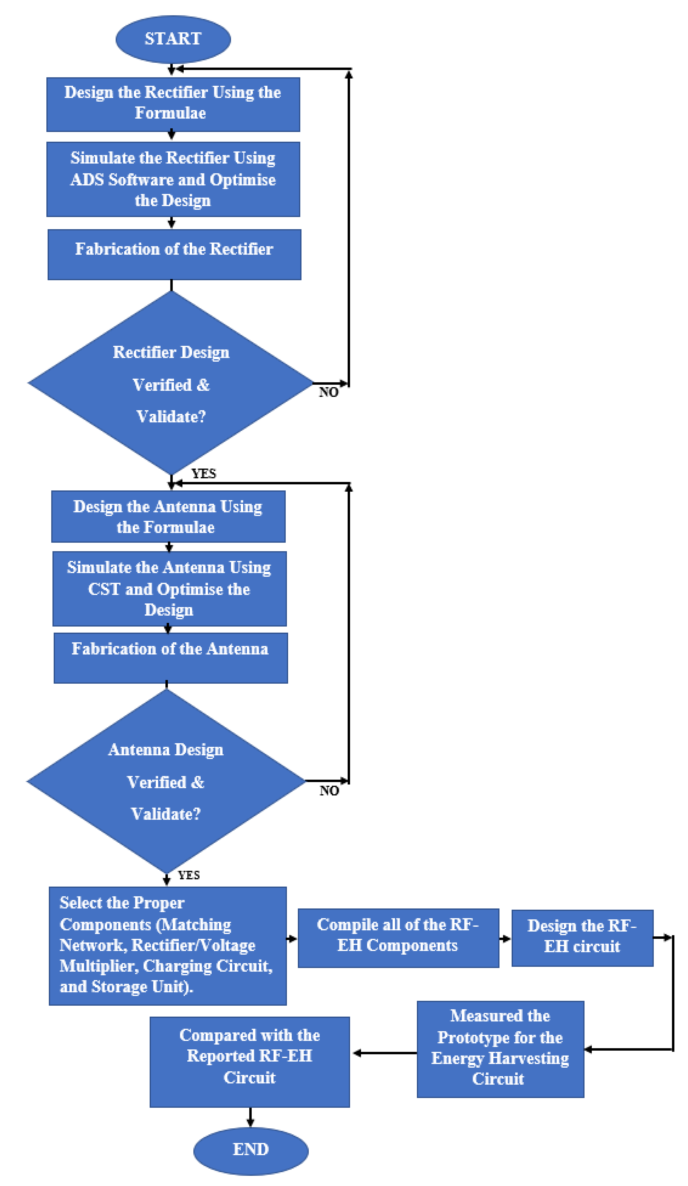
7. RF-EH Circuit
7.1. Antenna Configurations
7.1.1. Antennas Single Band
7.1.2. Broadband/Wideband Antennas
7.1.3. Antennas with Multiple Bands
7.2. A rectifier’s Configuration
7.3. Topologies of the Impedance Matching Network (IMN) and the Input RF Filter
7.3.1. RF Filter Designs
7.3.2. IMN Configurations
Single-Band Matching Network
Multiband Matching Network
7.4. Power Management Module
7.5. Storage Element
7.5.1. Capacitor and Supercapacitor
7.5.2. Batteries
7.6. The Influence of Multiband Frequencies on the RF Harvester Architecture
8. Existing Applications of RF-EH

9. Conclusions
Author Contributions
Funding
Conflicts of Interest
References
- Kim, J.; Lee, J.-W. Energy adaptive MAC for wireless sensor networks with RF energy transfer: Algorithm, analysis, and implementation. Telecommun. Syst. 2017, 64, 293–307. [Google Scholar] [CrossRef]
- Ugwuogo, J. On-Demand Energy Harvesting Techniques—A System Level Perspective; University of Waterloo: Waterloo, ON, Canada, 2012. [Google Scholar]
- Baroudi, U. Robot-Assisted Maintenance of Wireless Sensor Networks Using Wireless Energy Transfer. IEEE Sens. J. 2017, 17, 4661–4671. [Google Scholar] [CrossRef]
- Mekid, S.; Qureshi, A.; Baroudi, U. Energy Harvesting from Ambient Radio Frequency: Is it Worth it? Arab. J. Sci. Eng. 2016, 42, 2673–2683. [Google Scholar] [CrossRef]
- Nintanavongsa, P. A Survey on RF Energy Harvesting: Circuits and Protocols. Energy Procedia 2014, 56, 414–422. [Google Scholar] [CrossRef] [Green Version]
- Srinivasu, G.; Sharma, V.; Anveshkumar, N. A Survey on Conceptualization of RF Energy Harvesting. J. Appl. Sci. Comput. 2019, 6, 791–800. [Google Scholar]
- Kim, S.; Vyas, R.; Bito, J.; Niotaki, K.; Collado, A.; Georgiadis, A.; Tentzeris, M.M. Ambient RF Energy-Harvesting Technologies for Self-Sustainable Standalone Wireless Sensor Platforms. Proc. IEEE 2014, 102, 1649–1666. [Google Scholar] [CrossRef]
- Nella, A.; Gandhi, A.S. A survey on microstrip antennas for portable wireless communication system applications. In Proceedings of the 2017 International Conference on Advances in Computing, Communications and Informatics (ICACCI), Udupi, India, 13–16 September 2017; pp. 2156–2165. [Google Scholar] [CrossRef]
- Bankey, V.; Kumar, N.A. Design and performance issues of Microstrip Antennas. Int. J. Sci. Eng. Res. 2015, 6, 1572–1580. [Google Scholar] [CrossRef]
- Tesla, N. The Transmission of Electric Energy without Wires. Sci. Am. 1904, 57, 23760–23761. [Google Scholar] [CrossRef]
- Valenta, C.R.; Durgin, G.D. Harvesting wireless power: Survey of energy-harvester conversion efficiency in far-field, wireless power transfer systems. IEEE Microw. Mag. 2014, 15, 108–120. [Google Scholar]
- Alimenti, F.; Palazzi, V.; Mariotti, C.; Mezzanotte, P.; Correia, R.; Carvalho, N.B.; Roselli, L. Smart Hardware for Smart Objects: Microwave Electronic Circuits to Make Objects Smart. IEEE Microw. Mag. 2018, 19, 48–68. [Google Scholar] [CrossRef]
- Al-Bawri, S.S.; Islam, S.; Wong, H.Y.; Jamlos, M.F.; Narbudowicz, A.; Jusoh, M.; Sabapathy, T.; Islam, M.T. Metamaterial Cell-Based Superstrate towards Bandwidth and Gain Enhancement of Quad-Band CPW-Fed Antenna for Wireless Applications. Sensors 2020, 20, 457. [Google Scholar] [CrossRef] [PubMed] [Green Version]
- Kimionis, J.; Su, W.; Hester, J.; Bito, J.; He, X.; Lin, T.-H.; Tentzeris, M.M. Zero-Power Sensors for Smart Objects: Novel Zero-Power Additively Manufactured Wireless Sensor Modules for IoT Applications. IEEE Microw. Mag. 2018, 19, 32–47. [Google Scholar] [CrossRef]
- Hester, J.G.D.; Kimionis, J.; Tentzeris, M.M. Printed Motes for IoT Wireless Networks: State of the Art, Challenges, and Outlooks. IEEE Trans. Microw. Theory Tech. 2017, 65, 1819–1830. [Google Scholar] [CrossRef]
- Cansiz, M.; Altinel, D.; Kurt, G.K. Efficiency in RF energy harvesting systems: A comprehensive review. Energy 2019, 174, 292–309. [Google Scholar] [CrossRef]
- Bi, S.; Ho, C.K.; Zhang, R. Wireless powered communication: Opportunities and challenges. IEEE Commun. Mag. 2015, 53, 117–125. [Google Scholar] [CrossRef] [Green Version]
- Ibrahim, H.H.; Singh, M.S.J.; Al-Bawri, S.S.; Islam, M.T. Synthesis, Characterization and Development of Energy Harvesting Techniques Incorporated with Antennas: A Review Study. Sensors 2020, 20, 2772. [Google Scholar] [CrossRef]
- Harb, A. Energy harvesting: State-of-the-art. Renew. Energy 2011, 36, 2641–2654. [Google Scholar] [CrossRef]
- Lu, X.; Wang, P.; Niyato, D.; Kim, D.I.; Han, Z. Wireless Networks with RF Energy Harvesting: A Contemporary Survey. IEEE Commun. Surv. Tutor. 2015, 17, 757–789. [Google Scholar] [CrossRef] [Green Version]
- Cansiz, M.; Altinel, D.; Kurt, G.K. Effects of Different Modulation Techniques on Charging Time in RF Energy-Harvesting System. IEEE Trans. Instrum. Meas. 2020, 69, 6904–6911. [Google Scholar] [CrossRef]
- Aparicio, M.P.; Bakkali, A.; Pelegri-Sebastia, J.; Sogorb, T.; Llario, V.; Bou, A. Radio Frequency Energy Harvesting—Sources and Techniques. Renew. Energy-Util. Syst. Integr. 2016, 5, 1–16. [Google Scholar]
- Liang, Z.; Yuan, J. Modelling and optimisation of high-efficiency differential-drive complementary metal–oxide–semiconductor rectifier for ultra-high-frequency radio-frequency energy harvesters. IET Power Electron. 2019, 12, 588–597. [Google Scholar] [CrossRef]
- Finnegan, J.; Niotaki, K.; Brown, S. Exploring the Boundaries of Ambient RF Energy Harvesting with LoRaWAN. IEEE Internet Things J. 2020, 8, 5736–5743. [Google Scholar] [CrossRef]
- Alevizos, P.N.; Bletsas, A. Sensitive and Nonlinear Far-Field RF Energy Harvesting in Wireless Communications. IEEE Trans. Wirel. Commun. 2018, 17, 3670–3685. [Google Scholar] [CrossRef] [Green Version]
- Pinuela, M.; Mitcheson, P.D.; Lucyszyn, S. Ambient RF Energy Harvesting in Urban and Semi-Urban Environments. IEEE Trans. Microw. Theory Tech. 2013, 61, 2715–2726. [Google Scholar] [CrossRef]
- Cansiz, M.; Abbasov, T.; Kurt, M.B.; Çelik, A.R. Mobile measurement of radiofrequency electromagnetic field exposure level and statistical analysis. Measurement 2016, 86, 159–164. [Google Scholar] [CrossRef]
- Tran, L.-G.; Cha, H.-K.; Park, W.-T. RF power harvesting: A review on designing methodologies and applications. Micro Nano Syst. Lett. 2017, 5, 14. [Google Scholar] [CrossRef] [Green Version]
- Elsheakh, D. Microwave Antennas for Energy Harvesting Applications. In Microwave Systems and Applications; InTechOpen: London, UK, 2017. [Google Scholar] [CrossRef] [Green Version]
- Smith, J.R. Wirelessly Powered Sensor Networks and Computational RFID; Springer Science & Business Media: Berlin/Heidelberg, Germany, 2013. [Google Scholar]
- Bougas, I.D.; Papadopoulou, M.S.; Boursianis, A.D.; Kokkinidis, K.; Goudos, S.K. State-of-the-Art Techniques in RF Energy Harvesting Circuits. Telecom 2021, 2, 369–389. [Google Scholar] [CrossRef]
- Mishra, D.; EE Department IIT Hyderabad; Jana, S.; Basagni, S.; Chowdhury, K.; Heinzelman, W. Smart RF energy harvesting communications: Challenges and opportunities. IEEE Commun. Mag. 2015, 53, 70–78. [Google Scholar] [CrossRef] [Green Version]
- Kamalinejad, P.; Mahapatra, C.; Sheng, Z.; Mirabbasi, S.; Leung, V.C.M.; Guan, Y.L. Wireless energy harvesting for the Internet of Things. IEEE Commun. Mag. 2015, 53, 102–108. [Google Scholar] [CrossRef] [Green Version]
- Ren, J.; Hu, J.; Zhang, D.; Guo, H.; Zhang, Y.; Shen, X. RF Energy Harvesting and Transfer in Cognitive Radio Sensor Networks: Opportunities and Challenges. IEEE Commun. Mag. 2018, 56, 104–110. [Google Scholar] [CrossRef]
- Fleisch, D. A Student’s Guide to Maxwell’s Equations; Cambridge University Press: Cambridge, UK, 2008. [Google Scholar]
- Vico, F.; Ferrando, M.; Greengard, L.; Gimbutas, Z. The decoupled potential integral equation for time-harmonic electromagnetic scattering. Commun. Pure Appl. Math. 2016, 69, 771–812. [Google Scholar] [CrossRef] [Green Version]
- Abbas, Z.; Yoon, W. A Survey on Energy Conserving Mechanisms for the Internet of Things: Wireless Networking Aspects. Sensors 2015, 15, 24818–24847. [Google Scholar] [CrossRef] [PubMed] [Green Version]
- Yue, T.; Long, R.; Chen, H.; Khan, M.I.; Qi, H. Research of Effect of Energy-conservation Results: Evidence from Urban Household Survey. Energy Procedia 2016, 104, 293–298. [Google Scholar] [CrossRef]
- Visser, H.J.; Vullers, R.J.M. RF Energy Harvesting and Transport for Wireless Sensor Network Applications: Principles and Requirements. Proc. IEEE 2013, 101, 1410–1423. [Google Scholar] [CrossRef]
- Paradiso, J.; Starner, T. Energy Scavenging for Mobile and Wireless Electronics. IEEE Pervasive Comput. 2005, 4, 18–27. [Google Scholar] [CrossRef]
- Ambient, R. Energy Harvesting in Urban and Semi-Urban Environments Student Member, IEEE, Paul D. Mitcheson, Senior Member, IEEE, and Stepan Lucyszyn, Senior Member. IEEE Trans. Microw. Theory Tech. 2013, 61, 2715–2726. [Google Scholar]
- Ku, M.-L.; Li, W.; Chen, Y.; Liu, K.R. Advances in energy harvesting communications: Past, present, and future challenges. IEEE Commun. Surv. Tutor. 2015, 18, 1384–1412. [Google Scholar] [CrossRef]
- Abdin, Z.; Alim, M.; Saidur, R.; Islam, M.; Rashmi, W.; Mekhilef, S.; Wadi, A. Solar energy harvesting with the application of nanotechnology. Renew. Sustain. Energy Rev. 2013, 26, 837–852. [Google Scholar] [CrossRef]
- Al-Bawri, S.S.; Goh, H.H.; Islam, S.; Wong, H.Y.; Jamlos, M.F.; Narbudowicz, A.; Jusoh, M.; Sabapathy, T.; Khan, R.; Islam, M.T. Compact Ultra-Wideband Monopole Antenna Loaded with Metamaterial. Sensors 2020, 20, 796. [Google Scholar] [CrossRef] [Green Version]
- Herbert, G.M.J.; Iniyan, S.; Sreevalsan, E.; Rajapandian, S. A review of wind energy technologies. Renew. Sustain. Energy Rev. 2007, 11, 1117–1145. [Google Scholar] [CrossRef]
- Cuadras, A.; Gasulla, M.; Ferrari, V. Thermal energy harvesting through pyroelectricity. Sens. Actuators A Phys. 2010, 158, 132–139. [Google Scholar] [CrossRef]
- Lu, X.; Yang, S.-H. Thermal energy harvesting for WSNs. In Proceedings of the 2010 IEEE International Conference on Systems, Man and Cybernetics, Stanbul, Turkey, 10–13 October 2010; pp. 3045–3052. [Google Scholar]
- Cao, X.; Chiang, W.-J.; King, Y.-C.; Lee, Y.-K. Electromagnetic Energy Harvesting Circuit with Feedforward and Feedback DC–DC PWM Boost Converter for Vibration Power Generator System. IEEE Trans. Power Electron. 2007, 22, 679–685. [Google Scholar] [CrossRef] [Green Version]
- Lim, T.B.; Lee, N.M.; Poh, B.K. Feasibility study on ambient RF energy harvesting for wireless sensor network. In Proceedings of the 2013 IEEE MTT-S International Microwave Workshop Series on RF and Wireless Technologies for Biomedical and Healthcare Applications (IMWS-BIO), Singapore, 9–11 December 2013; pp. 1–3. [Google Scholar]
- Georgiadis, A. Energy harvesting for Autonomous Wireless Sensors and RFID’s. In Proceedings of the 2014 XXXIth URSI General Assembly and Scientific Symposium (URSI GASS), Beijing, China, 16–23 August 2014; pp. 1–5. [Google Scholar]
- Vyas, R.J.; Cook, B.B.; Kawahara, Y.; Tentzeris, M.M. E-WEHP: A Batteryless Embedded Sensor-Platform Wirelessly Powered From Ambient Digital-TV Signals. IEEE Trans. Microw. Theory Tech. 2013, 61, 2491–2505. [Google Scholar] [CrossRef]
- IEEE Std 145™2013. IEEE Standard for Definitions of Terms for Antennas. IEEE: Manhattan, NY, USA, 2014. [Google Scholar]
- Balanis, C.A. Antenna Theory: Analysis and Design; John Wiley & Sons: Hoboken, NJ, USA, 2015. [Google Scholar]
- Willkomm, D.; Machiraju, S.; Bolot, J.; Wolisz, A. Primary users in cellular networks: A large-scale measurement study. In Proceedings of the 2008 3rd IEEE Symposium on New Frontiers in Dynamic Spectrum Access Networks, Chicago, IL, USA, 14–17 October 2008; pp. 1–11. [Google Scholar]
- Mikki, S.M.; Antar, Y.M.M. On the Fundamental Relationship between the Transmitting and Receiving Modes of General Antenna Systems: A New Approach. IEEE Antennas Wirel. Propag. Lett. 2012, 11, 232–235. [Google Scholar] [CrossRef]
- Kalaagi, M.; Seetharamdoo, D. Electromagnetic energy harvesting systems in the railway environment: State of the art and proposal of a novel metamaterial energy harvester. In Proceedings of the 2019 13th European Conference on Antennas and Propagation (EuCAP), Krakow, Poland, 31 March–5 April 2019; pp. 1–5. [Google Scholar]
- Akin-Ponnle, A.E.; Carvalho, N.B. Energy Harvesting Mechanisms in a Smart City—A Review. Smart Cities 2021, 4, 476–498. [Google Scholar] [CrossRef]
- Erol-Kantarci, M.; Illig, D.; Rumbaugh, L.; Jemison, W. Energy-Harvesting Low-Power Devices in Cyber-Physical Systems. In Cyber-Physical Systems; Elsevier: Amsterdam, The Netherlands, 2017; pp. 55–74. [Google Scholar] [CrossRef]
- Marian, V.; Allard, B.; Vollaire, C.; Verdier, J. Strategy for Microwave Energy Harvesting From Ambient Field or a Feeding Source. IEEE Trans. Power Electron. 2012, 27, 4481–4491. [Google Scholar] [CrossRef]
- Cansiz, M.; Abbasov, T.; Kurt, M.B.; Çelik, A.R. Mapping of radio frequency electromagnetic field exposure levels in outdoor environment and comparing with reference levels for general public health. J. Exp. Sci. Environ. Epidemiol. 2016, 28, 161–165. [Google Scholar] [CrossRef] [PubMed]
- Mikeka, C.; Arai, H. Design issues in radio frequency energy harvesting system. In Sustainable Energy Harvesting Technologies-Past, Present and Future; BoD–Books on Demand: Norderstedt, Germany, 2011; pp. 235–256. [Google Scholar]
- Nalini, M.; Kumar, J.N.; Kumar, R.M.; Vignesh, M. Energy harvesting and management from ambient RF radiation. In Proceedings of the 2017 International Conference on Innovations in Green Energy and Healthcare Technologies (IGEHT), Coimbatore, India, 16–18 March 2017; pp. 1–3. [Google Scholar]
- Din, N.M.; Chakrabarty, C.K.; Ismail, A.B.; Devi, K.K.A.; Chen, W.-Y. Design of RF energy harvesting system for energizing low power devices. Prog. Electromagn. Res. 2012, 132, 49–69. [Google Scholar] [CrossRef] [Green Version]
- Ye, Y.; Wu, D.; Shu, Z.; Qian, Y. Overview of LTE Spectrum Sharing Technologies. IEEE Access 2016, 4, 8105–8115. [Google Scholar] [CrossRef]
- Fumtchum, A.; Tsafack, P.; Tanyi, E.; Hutu, F.; Villemaud, G. A Survey of RF Energy Harvesting Circuits. Int. J. Innov. Technol. Explor. Eng. 2021, 10, 99–106. [Google Scholar] [CrossRef]
- Swangpattaraphon, N. Radio Frequency Energy Harvesting for Embedded IoT Applications; San Diego State University: San Diego, CA, USA, 2020. [Google Scholar]
- Zeng, Z.; Estrada-Lopez, J.J.; Abouzied, M.A.; Sanchez-Sinencio, E. A Reconfigurable Rectifier with Optimal Loading Point Determination for RF Energy Harvesting From −22 dBm to −2 dBm. IEEE Trans. Circuits Syst. II Express Briefs 2019, 67, 87–91. [Google Scholar] [CrossRef]
- Khan, D.; Oh, S.J.; Shehzad, K.; Basim, M.; Verma, D.; Pu, Y.G.; Lee, M.; Hwang, K.C.; Yang, Y.; Lee, K.-Y. An Efficient Reconfigurable RF-DC Converter with Wide Input Power Range for RF Energy Harvesting. IEEE Access 2020, 8, 79310–79318. [Google Scholar] [CrossRef]
- Bouattour, G.; Kallel, B.; Derbel, H.B.J.; Kanoun, O. Passive Peak Voltage Sensor for Multiple Sending Coils Inductive Power Transmission System. In Proceedings of the 2019 IEEE International Symposium on Measurements & Networking (M&N), Catania, Italy, 8–10 July 2019; pp. 1–6. [Google Scholar] [CrossRef]
- Aksoyak, I.K.; Chletsou, A.; Papapolymerou, J.; Ulusoy, A.C. A high sensitivity RF energy harvester for diverse environments. In Proceedings of the 2020 50th European Microwave Conference (EuMC), Utrecht, The Netherlands, 12–14 January 2021; pp. 444–447. [Google Scholar]
- Murad, S.; Harun, A.; Isa, M.; Marzuki, A.; Sapawi, R. A Linear 0.98 mV Low-Dropout Voltage Regulator in 0.18-μm CMOS Technology. J. Phys. Conf. Ser. 2021, 1755, 012049. [Google Scholar] [CrossRef]
- Mimis, K.; Gibbins, D.; Dumanli, S.; Watkins, G.T. Ambient RF energy harvesting trial in domestic settings. IET Microw. Antennas Propag. 2015, 9, 454–462. [Google Scholar] [CrossRef]
- Adam, I.; Yasin, M.N.M.; Rahim, H.A.; Soh, P.J.; Abdulmalek, M.F. A compact dual-band rectenna for ambient RF energy harvesting. Microw. Opt. Technol. Lett. 2018, 60, 2740–2748. [Google Scholar] [CrossRef]
- AbdelGhany, O.M.; Sobih, A.G.; El-Tager, A.M. Outdoor RF spectral study available from cell-phone towers in sub-urban areas for ambient RF energy harvesting. IOP Conf. Ser. Mater. Sci. Eng. 2019, 610, 012086. [Google Scholar] [CrossRef] [Green Version]
- Caselli, M.; Tonelli, M.; Boni, A. Analysis and design of an integrated RF energy harvester for ultra low-power environments. Int. J. Circuit Theory Appl. 2019, 47, 1086–1104. [Google Scholar] [CrossRef]
- Wu, F.; Pan, D.; Liu, Y.; Fan, W.; Shen, R.; Chen, S. Environment RF Power Harvesting in IoT: A Resent Review. In Proceedings of the 2019 IEEE 6th International Symposium on Electromagnetic Compatibility (ISEMC), Nanjing, China, 1–4 November 2019; pp. 1–6. [Google Scholar]
- Surender, D.; Khan, T.; Talukdar, F.A.; De, A.; Antar, Y.M.; Freundorfer, A.P. Key Components of Rectenna System: A Comprehensive Survey. IETE J. Res. 2020, 1–27. [Google Scholar] [CrossRef]
- Padmanathan, S.; Al-Hadi, A.A.; Soh, P.J.; Al-Bawri, S.S. Dual Monopole Frequency Reconfigurable Antenna for MIMO 5G sub-6 GHz Mobile Terminal. J. Phys. Conf. Ser. 2021, 1962, 012042. [Google Scholar] [CrossRef]
- Li, K.; Shi, Y.; Shen, H.; Li, L. A Characteristic-Mode-Based Polarization-Reconfigurable Antenna and its Array. IEEE Access 2018, 6, 64587–64595. [Google Scholar] [CrossRef]
- Kim, S.; Kim, J.-I. A Circularly Polarized High-Gain Planar 2 × 2 Dipole-Array Antenna Fed by a 4-Way Gysel Power Divider for WLAN Applications. IEEE Antennas Wirel. Propag. Lett. 2019, 18, 1051–1055. [Google Scholar] [CrossRef]
- Chen, Z.; Li, H.-Z.; Wong, H.; Zhang, X.; Yuan, T. A Circularly-Polarized-Reconfigurable Patch Antenna with Liquid Dielectric. IEEE Open J. Antennas Propag. 2021, 2, 396–401. [Google Scholar] [CrossRef]
- Zhong, L.; Hong, J.-S.; Zhou, H.-C. A Dual-Fed Aperture-Coupled Microstrip Antenna with Polarization Diversity. IEEE Trans. Antennas Propag. 2016, 64, 4524–4529. [Google Scholar] [CrossRef]
- Nguyen-Trong, N.; Hall, L.; Fumeaux, C. A Frequency- and Polarization-Reconfigurable Stub-Loaded Microstrip Patch Antenna. IEEE Trans. Antennas Propag. 2015, 63, 5235–5240. [Google Scholar] [CrossRef]
- Ge, L.; Li, Y.; Wang, J. A low-profile reconfigurable cavity-backed slot antenna with frequency, polarization, and radiation pattern agility. IEEE Transactions on Antennas and Propagation 2017, 65, 2182–2189. [Google Scholar] [CrossRef]
- Chowdhury, R.; Chaudhary, R.K. An Approach to Generate Circular Polarization in a Modified Cylindrical-Shaped Dielectric Resonator Antenna Using PMC Boundary Approximation. IEEE Antennas Wirel. Propag. Lett. 2018, 17, 1727–1731. [Google Scholar] [CrossRef]
- Shabbir, T.; Islam, M.T.; Al-Bawri, S.S.; Aldhaheri, R.W.; Alharbi, K.H.; Aljohani, A.J.; Saleem, R. 16-Port Non-Planar MIMO Antenna System with Near-Zero-Index (NZI) Metamaterial Decoupling Structure for 5G Applications. IEEE Access 2020, 8, 157946–157958. [Google Scholar] [CrossRef]
- Lei, W.; Chu, H.; Guo, Y. Design of a Circularly Polarized Ground Radiation Antenna for Biomedical Applications. IEEE Trans. Antennas Propag. 2016, 64, 2535–2540. [Google Scholar] [CrossRef]
- Zheng, G.; Sun, B. High-Gain Normal-Mode Omnidirectional Circularly Polarized Antenna. IEEE Antennas Wirel. Propag. Lett. 2018, 17, 1104–1108. [Google Scholar] [CrossRef]
- Chen, Z.; Wong, H. Liquid Dielectric Resonator Antenna with Circular Polarization Reconfigurability. IEEE Trans. Antennas Propag. 2017, 66, 444–449. [Google Scholar] [CrossRef]
- Shah, S.I.H.; Tentzeris, M.M.; Lim, S. Low-Cost Circularly Polarized Origami Antenna. IEEE Antennas Wirel. Propag. Lett. 2017, 16, 2026–2029. [Google Scholar] [CrossRef]
- Sim, C.-Y.; Liao, Y.-J.; Lin, H.-L. Polarization Reconfigurable Eccentric Annular Ring Slot Antenna Design. IEEE Trans. Antennas Propag. 2015, 63, 4152–4155. [Google Scholar] [CrossRef]
- Li, L.; Yan, X.; Zhang, H.C.; Wang, Q. Polarization-and Frequency-Reconfigurable Patch Antenna Using Gravi-ty-Controlled Liquid Metal. IEEE Trans. Circuits Syst. II Express Briefs 2021, 69, 1029–1033. [Google Scholar] [CrossRef]
- Khade, S.; Chinchole, A.; Pandey, P.; Umredkar, S.; Magare, V.; Sonkusale, M. Circularly Polarized Cylindrical Slot Antenna with and without DGS. In Proceedings of the 2020 4th International Conference on Trends in Electronics and Informatics (ICOEI) (48184), Tirunelveli, India, 15–17 June 2020; pp. 309–313. [Google Scholar]
- Jaafar, A.N.; Ja’afar, H.; Pasya, I.; Yamada, Y.; Abdullah, R.; Aris, M.A.; Redzwan, F.N. Analysis of Helical Antenna for Wireless Application at 2.4 GHz. In Proceedings of the 2019 IEEE Asia-Pacific Conference on Applied Electromagnetics (APACE), Melacca, Malaysia, 25–27 November 2019; pp. 1–5. [Google Scholar]
- Chen, Y.-S.; You, J.-W. A Scalable and Multidirectional Rectenna System for RF Energy Harvesting. IEEE Trans. Compon. Packag. Manuf. Technol. 2018, 8, 2060–2072. [Google Scholar] [CrossRef]
- Sampe, J.; Semsudin, N.A.A.; Zulkifli, F.F.; Majlis, B.Y. Litar Penuai Tenaga Hibrid Mikro untuk Aplikasi Bioperubatan. J. Kejuruter. 2017, 29, 41–48. [Google Scholar] [CrossRef]
- Yang, Y.; Li, J.; Li, L.; Liu, Y.; Zhang, B.; Zhu, H.; Huang, K. A 5.8 GHz Circularly Polarized Rectenna with Harmonic Suppression and Rectenna Array for Wireless Power Transfer. IEEE Antennas Wirel. Propag. Lett. 2018, 17, 1276–1280. [Google Scholar] [CrossRef]
- Çelik, K.; Kurt, E. A novel meander line integrated E-shaped rectenna for energy harvesting applications. Int. J. RF Microw. Comput. Eng. 2018, 29, e21627. [Google Scholar] [CrossRef]
- Shen, S.; Chiu, C.-Y.; Murch, R.D. Multiport Pixel Rectenna for Ambient RF Energy Harvesting. IEEE Trans. Antennas Propag. 2017, 66, 644–656. [Google Scholar] [CrossRef]
- Hu, Y.-Y.; Sun, S.; Xu, H.; Sun, H. Grid-Array Rectenna with Wide Angle Coverage for Effectively Harvesting RF Energy of Low Power Density. IEEE Trans. Microw. Theory Tech. 2018, 67, 402–413. [Google Scholar] [CrossRef]
- Li, X.; Yang, L.; Huang, L. Novel Design of 2.45-GHz Rectenna Element and Array for Wireless Power Transmission. IEEE Access 2019, 7, 28356–28362. [Google Scholar] [CrossRef]
- Ghosh, S. Design and testing of rectifying antenna for RF energy scavenging in GSM 900 band. Int. J. Comput. Appl. 2016, 39, 36–44. [Google Scholar] [CrossRef]
- Sun, W.J.; Yang, W.W.; Chu, P.; Chen, J.X. A wideband stacked dielectric resonator antenna for 5G applications. Int. J. RF Microw. Comput. Aided Eng. 2019, 29, 10. [Google Scholar] [CrossRef]
- Sun, H.; Guo, Y.X.; Miao, H.; Zheng, Z. Design of a High-Efficiency 2.45-GHz Rectenna for Low-Input-Power Energy Harvesting. IEEE Antennas Wirel. Propag. Lett. 2012, 11, 929–932. [Google Scholar]
- Phongcharoenpanich, C.; Boonying, K. A 2.4-GHz dual polarized suspended square plate rectenna with inserted annular rectangular ring slot. Int. J. RF Microw. Comput. Eng. 2015, 26, 164–173. [Google Scholar] [CrossRef]
- Sun, H. An Enhanced Rectenna Using Differentially-Fed Rectifier for Wireless Power Transmission. IEEE Antennas Wirel. Propag. Lett. 2015, 15, 32–35. [Google Scholar] [CrossRef]
- Kumar, D.; Chaudhary, K. Design of an Improved Differentially Fed Antenna Array for RF Energy Harvesting. IETE J. Res. 2018, 66, 353–358. [Google Scholar] [CrossRef]
- Zheng, G.; Dang, K.; Sun, B.; Zhang, J. Design of perfect electrical conductor wall-loaded 2.45 GHz high-efficiency rectenna. Int. J. RF Microw. Comput. Aided Eng. 2018, 29, e21604. [Google Scholar] [CrossRef]
- Masius, A.A.; Wong, Y.C.; Lau, K.T. Miniature high gain slot-fed rectangular dielectric resonator antenna for IoT RF energy harvesting. AEU Int. J. Electron. Commun. 2018, 85, 39–46. [Google Scholar] [CrossRef]
- Song, C.; Huang, Y.; Zhou, J.; Zhang, J.; Yuan, S.; Carter, P. A High-Efficiency Broadband Rectenna for Ambient Wireless Energy Harvesting. IEEE Trans. Antennas Propag. 2015, 63, 3486–3495. [Google Scholar] [CrossRef] [Green Version]
- Shi, Y.; Fan, Y.; Li, Y.; Yang, L.; Wang, M. An Efficient Broadband Slotted Rectenna for Wireless Power Transfer at LTE Band. IEEE Trans. Antennas Propag. 2018, 67, 814–822. [Google Scholar] [CrossRef]
- Zhang, P.; Yi, H.; Liu, H.; Yang, H.; Zhou, G.; Li, L. Back-to-Back Microstrip Antenna Design for Broadband Wide-Angle RF Energy Harvesting and Dedicated Wireless Power Transfer. IEEE Access 2020, 8, 126868–126875. [Google Scholar] [CrossRef]
- Hemadeh, I.A.; Satyanarayana, K.; El-Hajjar, M.; Hanzo, L. Millimeter-Wave communications: Physical channel models, design considerations, antenna constructions, and link-budget. IEEE Commun. Surv. Tutor. 2017, 20, 870–913. [Google Scholar] [CrossRef] [Green Version]
- Agrawal, S.; Parihar, M.S.; Kondekar, P.N. Broadband Rectenna for Radio Frequency Energy Harvesting Application. IETE J. Res. 2017, 64, 347–353. [Google Scholar] [CrossRef]
- Agrawal, S.; Gupta, R.D.; Parihar, M.S.; Kondekar, P.N. A wideband high gain dielectric resonator antenna for RF energy harvesting application. AEU Int. J. Electron. Commun. 2017, 78, 24–31. [Google Scholar] [CrossRef]
- Al-Bawri, S.S.; Islam, M.T.; Shabbir, T.; Muhammad, G.; Islam, S.; Wong, H.Y. Hexagonal Shaped Near Zero Index (NZI) Metamaterial Based MIMO Antenna for Millimeter-Wave Application. IEEE Access 2020, 8, 181003–181013. [Google Scholar] [CrossRef]
- Singh, N.; Kanaujia, B.K.; Beg, M.T.; Mainuddin; Kumar, S.; Choi, H.C.; Kim, K.W. Low profile multiband rectenna for efficient energy harvesting at microwave frequencies. Int. J. Electron. 2019, 106, 2057–2071. [Google Scholar] [CrossRef]
- Lu, P.; Yang, X.-S.; Li, J.-L.; Wang, B.-Z. A Compact Frequency Reconfigurable Rectenna for 5.2- and 5.8-GHz Wireless Power Transmission. IEEE Trans. Power Electron. 2015, 30, 6006–6010. [Google Scholar] [CrossRef]
- Kimionis, J.; Collado, A.; Tentzeris, M.M.; Georgiadis, A. Octave and Decade Printed UWB Rectifiers Based on Nonuniform Transmission Lines for Energy Harvesting. IEEE Trans. Microw. Theory Tech. 2017, 65, 4326–4334. [Google Scholar] [CrossRef]
- Liu, W.J.; Wang, J.R.; Tong, M.S. A Novel Miniaturized Dual-Band Slot Antenna for WLAN/WiMAX Communications. In Proceedings of the 2020 IEEE MTT-S International Conference on Numerical Electromagnetic and Multiphysics Modeling and Optimization (NEMO), Hangzhou, China, 7–9 December 2020; pp. 1–3. [Google Scholar]
- Tangthong, N.; Nuangpirom, P.; Akatimagool, S. Design of triple band printed slot antenna for WLAN/WiMAX applications. In Proceedings of the 2015 IEEE Conference on Antenna Measurements & Applications (CAMA), Chiang Mai, Thailand, 30 November–2 December 2015; pp. 1–4. [Google Scholar]
- Hassan, N.; Zakaria, Z.; Sam, W.Y.; Hanapiah, I.N.M.; Mohamad, A.N.; Roslan, A.F.; Ahmad, B.H.; Ismail, M.K.; Aziz, M.Z.A.A. Design of dual-band microstrip patch antenna with right-angle triangular aperture slot for energy transfer application. Int. J. RF Microw. Comput. Eng. 2019, 29, e21666. [Google Scholar] [CrossRef] [Green Version]
- Mattsson, M.; Kolitsidas, C.I.; Jonsson, B.L.G. Dual-Band Dual-Polarized Full-Wave Rectenna Based on Differential Field Sampling. IEEE Antennas Wirel. Propag. Lett. 2018, 17, 956–959. [Google Scholar] [CrossRef]
- Derbal, M.C.; Nedil, M. A high gain rectenna for energy harvesting applications. In Proceedings of the 2019 IEEE International Symposium on Antennas and Propagation and USNC-URSI Radio Science Meeting, Atlanta, GA, USA, 7–12 July 2019; pp. 1505–1506. [Google Scholar]
- Aboualalaa, M.; Abdel-Rahman, A.B.; Allam, A.; Elsadek, H.; Pokharel, R.K. Design of a Dual-Band Microstrip Antenna with Enhanced Gain for Energy Harvesting Applications. IEEE Antennas Wirel. Propag. Lett. 2017, 16, 1622–1626. [Google Scholar] [CrossRef]
- Wang, M.; Fan, Y.; Yang, L.; Li, Y.; Feng, J.; Shi, Y. Compact dual-band rectenna for RF energy harvest based on a tree-like antenna. IET Microw. Antennas Propag. 2019, 13, 1350–1357. [Google Scholar] [CrossRef]
- Kumar, H.; Arrawatia, M.; Kumar, G. Broadband Planar Log-Periodic Dipole Array Antenna Based RF-Energy Harvesting System. IETE J. Res. 2017, 65, 39–43. [Google Scholar] [CrossRef]
- Derbal, M.C.; Nedil, M. A high gain dual band rectenna for rf energy harvesting applications. Prog. Electromagn. Res. Lett. 2020, 90, 29–36. [Google Scholar] [CrossRef]
- Chandrasekaran, K.T.; Nasimuddin, N.; Alphones, A.; Karim, M.F. Compact circularly polarized beam-switching wireless power transfer system for ambient energy harvesting applications. Int. J. RF Microw. Comput. Aided Eng. 2019, 29, e21642. [Google Scholar] [CrossRef] [Green Version]
- Sun, F.; Li, Y.; Wang, J.; Ma, Y.; Ge, L.; Ai, B.; He, R. A Millimeter-Wave Wideband Dual-Polarized Antenna Array with 3-D-Printed Air-Filled Differential Feeding Cavities. IEEE Trans. Antennas Propag. 2021, 70, 1020–1032. [Google Scholar] [CrossRef]
- Noor, F.S.M.; Zakaria, Z.; Lago, H.; Said, M.A.M. Dual-band aperture-coupled rectenna for radio frequency energy harvesting. Int. J. RF Microw. Comput. Eng. 2019, 29, e21651. [Google Scholar] [CrossRef] [Green Version]
- Shabbir, T.; Saleem, R.; Al-Bawri, S.S.; Shafique, M.F.; Islam, M.T. Eight-Port Metamaterial Loaded UWB-MIMO Antenna System for 3D System-in-Package Applications. IEEE Access 2020, 8, 106982–106992. [Google Scholar] [CrossRef]
- Ojo, R.; Jamlos, M.F.; Soh, P.J.; Bahari, N.; Lee, Y.S.; Al-Bawri, S.S.; Karim, M.S.A.; Khairi, K.A. A triangular MIMO array antenna with a double negative metamaterial superstrate to enhance bandwidth and gain. Int. J. RF Microw. Comput. Eng. 2020, 30, e22320. [Google Scholar] [CrossRef]
- Muhammad, S.; Tiang, J.J.; Wong, S.K.; Smida, A.; Ghayoula, R.; Iqbal, A. A Dual-Band Ambient Energy Harvesting Rectenna Design for Wireless Power Communications. IEEE Access 2021, 9, 99944–99953. [Google Scholar] [CrossRef]
- Shrestha, S.; Lee, S.R.; Choi, D.-Y. A New Fractal-Based Miniaturized Dual Band Patch Antenna for RF Energy Harvesting. Int. J. Antennas Propag. 2014, 2014, 805052. [Google Scholar] [CrossRef]
- Shukla, G.; Verma, S.; Sao, A.; Srivastava, S.; Tripathi, S. RF Energy Harvesting for GSM and Wi-Fi Band. In Proceedings of the 2020 URSI Regional Conference on Radio Science (URSI-RCRS), Varanasi, India, 12–14 February 2020; pp. 1–4. [Google Scholar]
- Singh, N.; Kanaujia, B.K.; Beg, M.T.; Mainuddin; Kumar, S.; Khandelwal, M.K. A dual band rectifying antenna for RF energy harvesting. J. Comput. Electron. 2018, 17, 1748–1755. [Google Scholar] [CrossRef]
- Sangare, F.; Han, Z. RF Energy Harvesting Networks: Existing Techniques and Hardware Technology. In Wireless Information and Power Transfer: A New Paradigm for Green Communications; Springer: Berlin/Heidelberg, Germany, 2018; pp. 189–239. [Google Scholar]
- Hamzi, I.; El Bakkali, M.; Aghoutane, M.; Touhami, N.A. Analysis of Series and Shunt Rectifier Circuits Topologies. In Proceedings of the 2019 International Conference on Wireless Technologies, Embedded and Intelligent Systems (WITS), Fez, Morocco, 3–4 April 2019; pp. 1–4. [Google Scholar] [CrossRef]
- Mansour, M.; Torigoe, S.; Yamamoto, S.; Kanaya, H. Compact and Simple High-Efficient Dual-Band RF-DC Rectifier for Wireless Electromagnetic Energy Harvesting. Electronics 2021, 10, 1764. [Google Scholar] [CrossRef]
- Sidhu, R.K.; Ubhi, J.; Agarwal, A. CMOS Rectifier Topologies for RF Energy Harvesting: A Review; Research Gate: Berlin, Germany, 2020. [Google Scholar]
- Deware, K.; Bhanwar, M. A Review on Design and Implementation for Voltage Drop in CMOS. Int. J. Technol. Res. Manag. ISSN 2017, 4, 2348–9006. [Google Scholar]
- Saffari, P.; Basaligheh, A.; Moez, K. An RF-to-DC Rectifier with High Efficiency over Wide Input Power Range for RF Energy Harvesting Applications. IEEE Trans. Circuits Syst. I Regul. Pap. 2019, 66, 4862–4875. [Google Scholar] [CrossRef]
- Zhang, H.; Zhong, Z.; Guo, Y.-X.; Wu, W. Differentially-Fed charge pumping rectifier design with an enhanced efficiency for ambient RF energy harvesting. In Proceedings of the 2017 IEEE MTT-S International Microwave Symposium (IMS), Honololu, HI, USA, 4–9 June 2017; pp. 613–616. [Google Scholar] [CrossRef]
- Gozel, M.A.; Kahriman, M.; Kasar, O. Design of an efficiency-enhanced Greinacher rectifier operating in the GSM 1800 band by using rat-race coupler for RF energy harvesting applications. Int. J. RF Microw. Comput. Eng. 2018, e21621. [Google Scholar] [CrossRef] [Green Version]
- Suh, Y.-H.; Chang, K. A high-efficiency dual-frequency rectenna for 2.45-and 5.8-GHz wireless power transmission. IEEE Trans. Microw. Theory Tech. 2002, 50, 1784–1789. [Google Scholar] [CrossRef] [Green Version]
- Agrawal, S.; Parihar, M.S.; Kondekar, P.N. Exact Performance Evaluation of RF Energy Harvesting with Different Circuit’s Elements. IETE Tech. Rev. 2017, 35, 514–522. [Google Scholar] [CrossRef]
- Nimo, A.; Grgic, D.; Reindl, L.M. Impedance optimization of wireless electromagnetic energy harvester for maximum output efficiency at μW input power. Act. Passiv. Smart Struct. Integr. Syst. 2012, 8341, 83410W. [Google Scholar] [CrossRef]
- Shariati, N.; Rowe, W.S.; Scott, J.R.; Ghorbani, K. Multi-Service highly sensitive rectifier for enhanced RF energy scavenging. Sci. Rep. 2015, 5, 9655. [Google Scholar] [CrossRef] [Green Version]
- Agrawal, S.; Parihar, M.S.; Kondekar, P. A dual-band RF energy harvesting circuit using 4th order dual-band matching network. Cogent Eng. 2017, 4, 1332705. [Google Scholar] [CrossRef]
- Liu, J.; Zhang, X.Y. Compact Triple-Band Rectifier for Ambient RF Energy Harvesting Application. IEEE Access 2018, 6, 19018–19024. [Google Scholar] [CrossRef]
- Hsu, C.-Y.; Lin, S.-C.; Tsai, Z.-M. Quadband Rectifier Using Resonant Matching Networks for Enhanced Harvesting Capability. IEEE Microw. Wirel. Compon. Lett. 2017, 27, 669–671. [Google Scholar] [CrossRef]
- Zeng, M.; Li, Z.; Andrenko, A.S.; Liu, X.; Tan, H.-Z. Differential voltage octuple rectifiers for wireless energy harvesting. Microw. Opt. Technol. Lett. 2017, 59, 1574–1578. [Google Scholar] [CrossRef]
- Takhedmit, H.; Cirio, L.; Merabet, B.; Allard, B.; Costa, F.; Vollaire, C.; Picon, O. Efficient 2.45 GHz rectenna design including harmonic rejecting rectifier device. Electron. Lett. 2010, 46, 811–812. [Google Scholar] [CrossRef]
- Angulo, F.; Navarro, L.; Quintero, M.C.G.; Pardo, M. A Simple WiFi Harvester with a Switching-Based Power Management Scheme to Collect Energy from Ordinary Routers. Electronics 2021, 10, 1191. [Google Scholar] [CrossRef]
- Caselli, M.; Ronchi, M.; Boni, A. Power Management Circuits for Low-Power RF Energy Harvesters. J. Low Power Electron. Appl. 2020, 10, 29. [Google Scholar] [CrossRef]
- Calautit, K.; Nasir, D.S.; Hughes, B.R. Low power energy harvesting systems: State of the art and future challenges. Renew. Sustain. Energy Rev. 2021, 147, 111230. [Google Scholar] [CrossRef]
- Prauzek, M.; Konecny, J.; Borova, M.; Janosova, K.; Hlavica, J.; Musilek, P. Energy Harvesting Sources, Storage Devices and System Topologies for Environmental Wireless Sensor Networks: A Review. Sensors 2018, 18, 2446. [Google Scholar] [CrossRef] [Green Version]
- Khan, F.U. State of the art in acoustic energy harvesting. J. Micromech. Microeng. 2015, 25, 023001. [Google Scholar] [CrossRef]
- Marshall, B.R.; Morys, M.M.; Durgin, G.D. Parametric analysis and design guidelines of RF-to-DC Dickson charge pumps for RFID energy harvesting. In Proceedings of the 2015 IEEE International Conference on RFID (RFID), San Diego, CA, USA, 15–17 April 2015; pp. 32–39. [Google Scholar] [CrossRef]
- Chan, K.-Y.; Pham, D.Q.; Demir, B.; Yang, D.; Mayes, E.L.; Mouritz, A.P.; Ang, A.S.; Fox, B.; Lin, H.; Jia, B.; et al. Graphene oxide thin film structural dielectric capacitors for aviation static electricity harvesting and storage. Compos. Part B Eng. 2020, 201, 108375. [Google Scholar] [CrossRef]
- Deka, B.K.; Hazarika, A.; Lee, S.; Park, Y.-B.; Park, H.W. Triboelectric-Nanogenerator-Integrated structural supercapacitor based on highly active P-doped branched Cu–Mn selenide nanowires for efficient energy harvesting and storage. Nano Energy 2020, 73, 104754. [Google Scholar] [CrossRef]
- Sarker, M.; Saad, M.; Olazagoitia, J.; Vinolas, J. Review of Power Converter Impact of Electromagnetic Energy Harvesting Circuits and Devices for Autonomous Sensor Applications. Electronics 2021, 10, 1108. [Google Scholar] [CrossRef]
- Bhat, R.V.; Motani, M.; Lim, T.J. Energy Harvesting Communication Using Finite-Capacity Batteries with Internal Resistance. IEEE Trans. Wirel. Commun. 2017, 16, 2822–2834. [Google Scholar] [CrossRef] [Green Version]
- Krieger, E.M.; Arnold, C. Effects of undercharge and internal loss on the rate dependence of battery charge storage efficiency. J. Power Sources 2012, 210, 286–291. [Google Scholar] [CrossRef]
- Chen, G.Z. Supercapacitor and supercapattery as emerging electrochemical energy stores. Int. Mater. Rev. 2016, 62, 173–202. [Google Scholar] [CrossRef] [Green Version]
- Li, S.; Cheng, F.; Gu, C.; Yu, S.; Huang, K. Efficient dual-band rectifier using stepped impedance stub matching network for wireless energy harvesting. IEEE Microwave and Wireless Components Letters 2021, 31, 921–924. [Google Scholar] [CrossRef]
- Song, C.; Huang, Y.; Zhou, J.; Carter, P. Recent advances in broadband rectennas for wireless power transfer and ambient RF energy harvesting. In Proceedings of the 2017 11th European Conference on Antennas and Propagation (EUCAP), Paris, France, 19–24 March 2017. [Google Scholar] [CrossRef]
- Kuhn, V.; Lahuec, C.; Seguin, F.; Person, C. A Multi-Band Stacked RF Energy Harvester with RF-to-DC Efficiency Up to 84%. IEEE Trans. Microw. Theory Tech. 2015, 63, 1768–1778. [Google Scholar] [CrossRef]
- Chandravanshi, S.; Sarma, S.S.; Akhtar, M.J. Design of Triple Band Differential Rectenna for RF Energy Harvesting. IEEE Trans. Antennas Propag. 2018, 66, 2716–2726. [Google Scholar] [CrossRef]
- Palazzi, V.; Hester, J.; Bito, J.; Alimenti, F.; Kalialakis, C.; Collado, A.; Mezzanotte, P.; Georgiadis, A.; Roselli, L.; Tentzeris, M.M. A Novel Ultra-Lightweight Multiband Rectenna on Paper for RF Energy Harvesting in the Next Generation LTE Bands. IEEE Trans. Microw. Theory Tech. 2017, 66, 366–379. [Google Scholar] [CrossRef]
- Shen, S.; Zhang, Y.; Chiu, C.-Y.; Murch, R.D. A Triple-Band High-Gain Multibeam Ambient RF Energy Harvesting System Utilizing Hybrid Combining. IEEE Trans. Ind. Electron. 2019, 67, 9215–9226. [Google Scholar] [CrossRef]
- Singh, N.; Kumar, S.; Kanaujia, B.K.; Beg, M.T.; Mainuddin; Kumar, S. A compact broadband GFET based rectenna for RF energy harvesting applications. Microsyst. Technol. 2020, 26, 1881–1888. [Google Scholar] [CrossRef]
- Koohestani, M.; Tissier, J.; Latrach, M. A miniaturized printed rectenna for wireless RF energy harvesting around 2.45 GHz. AEU Int. J. Electron. Commun. 2020, 127, 153478. [Google Scholar] [CrossRef]
- Chi, Y.-J.; Lin, C.-H.; Chiu, C.-W. Design and modeling of a wearable textile rectenna array implemented on Cordura fabric for batteryless applications. J. Electromagn. Waves Appl. 2020, 34, 1782–1796. [Google Scholar] [CrossRef]
- Potti, D.; Mohammed, G.N.A.; Savarimuthu, K.; Narendhiran, S.; Rajamanickam, G. An ultra-wideband rectenna using optically transparent Vivaldi antenna for radio frequency energy harvesting. Int. J. RF Microw. Comput. Eng. 2020, 30. [Google Scholar] [CrossRef]
- Pandey, R.; Shankhwar, A.K.; Singh, A.A. An Improved CONVERSION efficiency of 1.975 to 4.744 ghz Rectenna for Wireless Sensor Applications. Prog. Electromagn. Res. C 2021, 109, 217–225. [Google Scholar] [CrossRef]
- Fakharian, M.M. A Wideband Rectenna Using High Gain Fractal Planar Monopole Antenna Array for RF Energy Scavenging. Int. J. Antennas Propag. 2020, 2020, 3489323. [Google Scholar] [CrossRef]
- Eltresy, N.A.; Dardeer, O.M.; Al-Habal, A.; ElHariri, E.; Abotaleb, A.M.; Elsheakh, D.N.; Khattab, A.; Taie, S.A.; Mostafa, H.; Elsadek, H.A.; et al. Smart Home IoT System by Using RF Energy Harvesting. J. Sens. 2020, 2020, 8828479. [Google Scholar] [CrossRef]
- Benhamou, A.; Tellache, M.; Hebib, S.; Mahfoudi, H. A wide input power range rectenna for energy harvesting and wireless power transfer applications. Int. J. RF Microw. Comput. Eng. 2020, 30. [Google Scholar] [CrossRef]
- He, Z.; Liu, C. A Compact High-Efficiency Broadband Rectifier with a Wide Dynamic Range of Input Power for Energy Harvesting. IEEE Microw. Wirel. Compon. Lett. 2020, 30, 433–436. [Google Scholar] [CrossRef]
- Reed, R.; Pour, F.L.; Ha, D.S. An Efficient 2.4 GHz Differential Rectenna for Radio Frequency Energy Harvesting. In Proceedings of the 2020 IEEE 63rd International Midwest Symposium on Circuits and Systems (MWSCAS), Springfield, MA, USA, 9–12 August 2020; pp. 208–212. [Google Scholar]
- Hu, Y.-Y.; Sun, S.; Su, H.-J.; Yang, S.; Hu, J. Dual-Beam Rectenna Based on a Short Series-Coupled Patch Array. IEEE Trans. Antennas Propag. 2021, 69, 5617–5630. [Google Scholar] [CrossRef]
- Chandrasekaran, K.T.; Agarwal, K.; Nasimuddin; Alphones, A.; Mittra, R.; Karim, M.F. Compact Dual-Band Metamaterial-Based High-Efficiency Rectenna: An Application for Ambient Electromagnetic Energy Harvesting. IEEE Antennas Propag. Mag. 2020, 62, 18–29. [Google Scholar] [CrossRef]
- Almoneef, T.S. Design of a Rectenna Array without a Matching Network. IEEE Access 2020, 8, 109071–109079. [Google Scholar] [CrossRef]
- Lin, W.; Ziolkowski, R.W. Electrically Small, Single-Substrate Huygens Dipole Rectenna for Ultracompact Wireless Power Transfer Applications. IEEE Trans. Antennas Propag. 2020, 69, 1130–1134. [Google Scholar] [CrossRef]
- Wagih, M.; Hilton, G.S.; Weddell, A.S.; Beeby, S. Broadband Millimeter-Wave Textile-Based Flexible Rectenna for Wearable Energy Harvesting. IEEE Trans. Microw. Theory Tech. 2020, 68, 4960–4972. [Google Scholar] [CrossRef]
- Wagih, M.; Hillier, N.; Yong, S.; Weddell, A.S.; Beeby, S. RF-Powered Wearable Energy Harvesting and Storage Module Based on E-Textile Coplanar Waveguide Rectenna and Supercapacitor. IEEE Open J. Antennas Propag. 2021, 2, 302–314. [Google Scholar] [CrossRef]
- Wagih, M.; Hilton, G.S.; Weddell, A.S.; Beeby, S. Dual-Band Dual-Mode Textile Antenna/Rectenna for Simultaneous Wireless Information and Power Transfer (SWIPT). IEEE Trans. Antennas Propag. 2021, 69, 6322–6332. [Google Scholar] [CrossRef]
- De Donno, D.; Catarinucci, L.; Tarricone, L. RAMSES: RFID Augmented Module for Smart Environmental Sensing. IEEE Trans. Instrum. Meas. 2014, 63, 1701–1708. [Google Scholar] [CrossRef]
- Hossain, M.J.; Faruque, M.R.I.; Islam, M.T. Perfect metamaterial absorber with high fractional bandwidth for solar energy harvesting. PLoS ONE 2018, 13, e0207314. [Google Scholar] [CrossRef] [Green Version]
- Yunus, N.H.M.; Yunas, J.; Pawi, A.; Rhazali, Z.A.; Sampe, J. Investigation of micromachined antenna substrates operating at 5 GHz for RF energy harvesting applications. Micromachines 2019, 10, 146. [Google Scholar] [CrossRef] [Green Version]
- Al-Bawri, S.S.; Islam, M.T.; Hossain, K.; Sabapathy, T.; Jusoh, M. Left-Handed Characteristics Tunable C-Shaped Varactor Loaded Textile Metamaterial for Microwave Applications. Computers, Materials and Continua 2022, 71, 611–628. [Google Scholar]
- Hossain, K.; Sabapathy, T.; Jusoh, M.; Abdelghany, M.A.; Soh, P.J.; Osman, M.N.; Yasin, M.N.M.; Rahim, H.A.; Al-Bawri, S.S. A Negative Index Nonagonal CSRR Metamaterial-Based Compact Flexible Planar Monopole Antenna for Ultrawideband Applications Using Viscose-Wool Felt. Polymers 2021, 13, 2819. [Google Scholar] [CrossRef] [PubMed]
- Hossain, K.; Sabapathy, T.; Jusoh, M.; Soh, P.J.; Jamaluddin, M.H.; Al-Bawri, S.S.; Osman, M.N.; Ahmad, R.B.; Rahim, H.A.; Mohd Yasin, M.N. Electrically tunable left-handed textile metamaterial for microwave applications. Materials 2021, 14, 1274. [Google Scholar] [CrossRef] [PubMed]


| Environment | Band | Number of Stations | Maximum PIN, dBm | SBA Threshold nW/cm2 |
|---|---|---|---|---|
| Urban | GSM-900 | 8 | −19.2 | 230 |
| GSM-1800 | 7 | −31.3 | 450 | |
| DTV (during switch over) | 10 | −34 | 40 | |
| Semi-urban | GSM-900 | 2 | −22.3 | 230 |
| GSM-1800 | 3 | −43.5 | 450 | |
| DTV (during switch over) | 0 | −37 | 40 |
| Ref. | Frequency (GHz) | Max Conversion Efficiency (%) | Circuit Size (mm3) | Pin (dBm) | Max Gain (dBi) | Max Harvested DC Output Voltage (v) | Substrate | Distance (m) | Diode Type |
|---|---|---|---|---|---|---|---|---|---|
| [173] | 24 | 80 | 40 ×40 ×1.6 | 4.9 | 7.8 | 6.82 | FR-4 | 1.5 | Schottky |
| CMOS | |||||||||
| [174] | 2.45 | 20 | 24.9 × 8.6 × 1.6 | −20 | 0.8 | 0.097 | FR-4 | 0.9 | HSMS-2852 Schottky |
| [175] | 2.45 | - | 160 × 130 × 0.55 | –40 to 0 | 5 | 1.05@1.5 m | Cordura fabric | 1.5 | HSMS-2862 |
| 1@2 m | 2 | Schottky | |||||||
| [176] | 3.1–8 | 69 | 6.3 × 13 × 0.8 | −10 | 3.2 | - | FR-4 | 0.5 | SMS 7630 |
| [177] | 1.975–4.744 | 88.58 | 40 × 45 × 1.6 | 0 | 4.3 | 10.703 | FR-4 | 2 | HSMS 270B |
| Schottky | |||||||||
| [178] | 0.91–2.55 | 68 | 165 × 165 × 0.8 | −10 | 5 to 8.3 | 0.243 | FR-4 | - | HSMS-285C |
| [179] | 1.7–3 | 60 | 178 × 148 × 0.813 | - | 9.902 | ~3.7 | Roger | 0.75 | SMS7630 |
| RO4003C | |||||||||
| [180] | 2.4 | 50 | 63.7 × 45.6 × 1.6 | −10 to 17 | 5.3 | 3 | FR-4 | 1–2.5 | HSMS 2850 and SMS7630 |
| [181] | 2.1 & 3.3 | 76.3 | 31 × 18 × 1 | 4 to 16 | - | - | F4B | - | HSMS286 |
| [182] | 2.4 | 69.3 | 4 × 11.7 × 1.6 | 5.2 | 5.9 | 3.5 | RO4003C | - | SMS7630 |
| [183] | 2.45 | 19.5–44.6 | 150 × 80 × 4 | −9.48 | 8.53 | - | RO4003 | - | SMS7630 |
| [184] | 2.45 and 3.6 GHz | 59%@ | 44 × 24.5 × 0.06 | 2 | 2.6 d@ 2.45 1.6 d@ 3.6 | - | Rogers R04003 | 0.65 | SMS-7630 |
| 2.45 | |||||||||
| 41% @3.6 | |||||||||
| [185] | 2.2 | 50 | 71 × 71 × 1.6 | 29 | 7:46 | 0.516 in parallel 1.087 in series | RT/duroid | 1 | SMS7621 |
| 5880 Rogers | |||||||||
| [186] | 0.909 | 88 | 99.5 × 26 × 0.508 | −10 | 4.6 | 7 | Rogers 5880 | 1.2 | HSMS286C |
| [187] | 20–26.5 | 70 | 32.6 × 16 × 4 | 27 | 8 | 6.5 | Textile | 0.12 | SMS7630 |
| MA4E-1319 | |||||||||
| [188] | 0.915 | 80 | 115 × 15 × 1.4 | −7 | 2.3 | 1.8 | Textile | 4.2 | BAT15-04R |
| [189] | 2.4 | 63 | - | −10 | 1.7 | 0.65 | Felt | 0.89 | SMS7630-079lf |
| 0.83 |
Publisher’s Note: MDPI stays neutral with regard to jurisdictional claims in published maps and institutional affiliations. |
© 2022 by the authors. Licensee MDPI, Basel, Switzerland. This article is an open access article distributed under the terms and conditions of the Creative Commons Attribution (CC BY) license (https://creativecommons.org/licenses/by/4.0/).
Share and Cite
Ibrahim, H.H.; Singh, M.J.; Al-Bawri, S.S.; Ibrahim, S.K.; Islam, M.T.; Alzamil, A.; Islam, M.S. Radio Frequency Energy Harvesting Technologies: A Comprehensive Review on Designing, Methodologies, and Potential Applications. Sensors 2022, 22, 4144. https://doi.org/10.3390/s22114144
Ibrahim HH, Singh MJ, Al-Bawri SS, Ibrahim SK, Islam MT, Alzamil A, Islam MS. Radio Frequency Energy Harvesting Technologies: A Comprehensive Review on Designing, Methodologies, and Potential Applications. Sensors. 2022; 22(11):4144. https://doi.org/10.3390/s22114144
Chicago/Turabian StyleIbrahim, Husam Hamid, Mandeep Jit Singh, Samir Salem Al-Bawri, Sura Khalil Ibrahim, Mohammad Tariqul Islam, Ahmed Alzamil, and Md Shabiul Islam. 2022. "Radio Frequency Energy Harvesting Technologies: A Comprehensive Review on Designing, Methodologies, and Potential Applications" Sensors 22, no. 11: 4144. https://doi.org/10.3390/s22114144