Article

Comparison of the Moist Material Relative Permittivity Readouts Using the Non-Invasive Reflectometric Sensors and Microwave Antenna

1
Faculty of Environmental Engineering, Lublin University of Technology, Nadbystrzycka 40B Str., 20-618 Lublin, Poland
2
Aquapol Polska CPV, Żeromskiego 12 Str., 58-160 Świebodzice, Poland
3
Faculty of Civil Engineering and Architecture, Lublin University of Technology, Nadbystrzycka 40 Str., 20-618 Lublin, Poland
4
Faculty of Electronics, Military University of Technology, Gen. Sylwestra Kaliskiego 2 Str., 00-908 Warsaw, Poland
*
Author to whom correspondence should be addressed.
Sensors 2022, 22(10), 3622; https://doi.org/10.3390/s22103622
Submission received: 20 April 2022 / Revised: 4 May 2022 / Accepted: 7 May 2022 / Published: 10 May 2022
(This article belongs to the Special Issue Smart TDR Sensors for Moisture Measurement)

Abstract

:
The article concerns the issue of non-invasive moisture sensing in building materials. Two techniques that enable evaluating the value of the relative permittivity of the material, being the measure of porous material moisture, have been utilized for the research. The first is the microwave technique that utilizes the non-contact measurement of velocity of microwave radiation across the tested material and the second is the time domain reflectometry (TDR) technique based on the measurement of electromagnetic pulse propagation time along the waveguides, being the elements of sensor design. The tested building material involved samples of red ceramic brick that differed in moisture, ranging between 0% and 14% moisture by weight. The main goal of the research was to present the measuring potential of both techniques for moisture evaluation as well as emphasize the advantages and disadvantages of each method. Within the research, it was stated that both methods provide similar measuring potential, with a slight advantage in favor of a microwave non-contact sensor over surface TDR sensor designs.

1. Introduction

1.1. Problem of Moisture Presence in the Building Envelopes

Water presence in building envelopes is a typical phenomenon that can be a serious exploitation problem. It may occur in historical buildings, but also in newly built houses. The major sources of water presence are: inappropriate building construction, poor ventilation, as well as failures of water supply systems and flooding [1,2,3,4].
Water can appear inside the envelopes under several forms. It may be present as free water, chemically bound water, physically bound water, and water vapor, condensation and capillary water [5,6]. Free water is the factor which has the greatest influence on the performance of objects and most harmful for buildings. When contained inside the envelopes, it may enhance the value of material thermal conductivity coefficient [7,8], significantly influencing the energetic performance of the buildings [9]. The water present in building barriers can be also divided into condensation water and capillary water. The source of the condensation water is a lack or improper performance of the ventilation system. On the other hand, the presence of the capillary water mainly means the influence of ground water rise in the porous structure of the material and lack or destruction of the horizontal or vertical water-proof isolation [10,11,12,13,14,15].
The water that is present inside the building materials causes the construction decay in several processes that can be divided into the physical, chemical, and biological [16]. Among the physical-chemical processes, frosting and defrosting [17,18,19] should be mentioned, in addition to shrinking and expanding [20,21] as well as mechanical damage caused by salt crystallization [22,23,24]. Moreover, the phenomenon of metal corrosion caused by water which occurs mainly in the reinforcing steel. Finally, the destruction of the finishing materials must be mentioned among the physical-chemical processes [25,26].
Biological processes represent another reason for wearing out of building barriers due to the excessive water presence. The microorganisms present in moist materials cause the decay of the building envelopes with the most dangerous fungal development [1,27,28,29], which negatively influences the indoor air parameters. Currently, this problem becomes more important due to the increased amount of time (90%) spent by people indoors, where the pollutant concentrations are significantly higher compared to the outdoor air [30].
All the above-mentioned consequences of moisture presence in the buildings envelopes that negatively influence their performance, mainly the deteriorating indoor air quality, represent the cause of so-called sick building syndrome (SBS), often caused by fungal metabolites, predominantly microbial volatile organic compounds (mVOC), mycotoxins, spores, etc. [16,29,31]. Another problem is the mechanical degradation of the masonry, which in turn may be the reason for a building demolition.

1.2. Material Relative Permittivity

The structure of the porous building material consists of the three phases, namely solid, liquid, and gaseous [32,33]. Each phase has a certain value of relative permittivity. The relative permittivity of a three-phase mixture is the result of the relative permittivity of individual phases. The relative permittivity values of the individual phases of building structures are as follows: air, 1; solid phase, 1–15; water, 80 [34,35,36]. Concerning the building materials, the values of relative permittivity are the following: according to Davis and Annan [37], the relative permittivity of granite equals 4–6, clay—5–10 and sand—3–5. According to Daniels [38], the relative permittivity of granite equals 5, sandstone 2–3, clay 2–6, and sand 4–6. Korhonen et al. [39] evaluated the relative permittivity of sand as equal to 2.9, cement 2.7, dry concrete 5.4, and dry mortar 3.9. Finally, Mohamed [40] gives the value of relative permittivity of the following minerals: calcite 6.4–8.5, gypsum 6.5, orthoclase 5.6, and finally quartz 4.5. As can be noticed, the relative permittivity of water clearly differs from that of other media. This is a consequence of the asymmetric charge distribution in its molecule and its polar structure [41].
The dielectric permittivity ε is a measure of the behavior of matter particles after the application of an external, alternating electric field. Due to the application of an electric field to the medium, the water molecules rotate in the direction of the applied field. The consequence of this ordering of dipoles is the accumulation of energy released when the electric field disappears [34].
The electrical permittivity of the materials is a complex number that consists of a real (ε′) and an imaginary (ε″) part. The real part describes the baseline value of moisture estimation using dielectric techniques, namely the amount of energy released in the alternating field, and the imaginary part includes energy losses due to ionic conductivity, which are strongly dependent on material salinity [42]. The complex relative permittivity of a lossy medium can be calculated according to the following extended formula [32,41,43,44,45,46]:
ε r = ε r i ε r + σ 0 ε 0 ω
where εr denotes the real part of relative permittivity of medium, εr the imaginary part of relative permittivity of medium, i the imaginary unit (i2 = −1), σ0 the electrical conductivity [S/m], ε0 the permittivity of vacuum (ε0 = 8.85 × 10⁻¹² F/m), and ω the angular frequency of the external electric field [rad/s].
The operating frequencies of microwave and reflectometric techniques utilized in the presented research reach the values between 1 and 8 GHz [44], which are high enough to decrease the influence of the imaginary part on the total value of the complex permittivity of examined medium, even if loaded with some ionic conductivity. Thus, it can be assumed that the ionic conductivity has low effect on the microwave as well as reflectometric moisture readouts. Salinity diminishes the pulse energy and the measuring markers are flatter. This feature can be also positively utilized for salinity evaluation of moist material, based on suitable signal attenuation interpretation [47].

1.3. Time Domain Reflectometry Technique for Evaluation of Moist Material Relative Permittivity Value

Time domain reflectometry (TDR) is an electric technique that utilizes the measurement of relative permittivity to evaluate the moisture of porous materials [33]. Measurement using this method consists in determining the travel time of the electromagnetic pulse along the rods of TDR probes inserted into the examined material. TDR probes usually consist of a coaxial cable, head, and measuring rods embedded in the tested material. The readings are based on marking the reflections on the individual discontinuities of the sensor waveguide, which are part of the sensor design. Typically, the described discontinuities are at the beginning and end of the probe. In detail, the performance of the TDR technique is described in the following articles [42,48,49,50].
Another approach to moisture evaluation, especially in rigid porous media such as building materials, is presented by surface, non-invasive sensors that are described in many studies [36,51,52,53,54,55,56]. Surface sensors are utilizable for moisture detection without the necessity of introducing the sensing elements inside the material. In comparison to traditional invasive probes, they provide worse accuracy and smaller sensitivity; on the other hand, they provide the readouts without changing the structure of the material.
The TDR method uses two types of pulses emitted by pulse generators: a stepped pulse [34] and a needle pulse [57]. The data collected by a TDR multimeter from the sensing probe consists in set of voltages distributed in time, called waveforms or reflectograms. In this research, a needle pulse generator with a rise time of 300 ps [57,58] that is more widely described in Section 2 and the exemplary waveforms achieved in the research are presented in Section 3. Waveform interpretation focused on the recognition of signal disturbances and propagation time enables to evaluate the relative permittivity of the materials according to the following formula [57]:
ε r = c · t p 2 L
where c denotes the velocity of light in vacuum [m/s], tp the time of signal propagation [s], and L the distance between to marked points of the TDR sensor [m].
Establishing the value of the relative permittivity enables to evaluate the moisture of the material by applying theoretical or physical models available in literature [59,60,61] or individual calibration based on experimental tests [34,48,62,63,64].

1.4. Microwave Measurement Technique to Evaluate the Permittivity Value of the Moist Material

Application of microwave techniques for the determination of the permittivity of a material may be divided into three approaches. The first is the use of special measurement setup, mainly based on a microwave resonator. In this approach, a microwave resonating circuit, most frequently a cavity one, is loaded with a small sample of the investigated material [65]. The sample should be small enough or with low losses, in order to cause only a small disturbance of the electric field distribution inside a resonating cavity. This approach is called the field perturbation method. The resonator is connected as a two-port to the measurement setup, which most frequently is based on vector network analyzer (VNA). The measurement procedure relies on finding the transmittance versus frequency characteristics. Then, the modulus of S21 scattering parameter along the frequency carries the information about the resonance frequency value and the quality factor (Q-factor). There is a mathematical procedure to derive the values of sample permittivity from the measurements of resonant frequency shift and Q-factor values. However, this method requires physical contact with the material sample. Moreover, the sample must have a specific shape related to the resonator type (i.e., thin slab, cylinder, or powdered form). Non-destructive measurements in situ are not feasible.
The second common way is the use of a set of two antennas and performing the transmittance measurement through a sample or a full masonry wall. Then, the concept relies on the derivation of permittivity from the measurement results performed for the S21 scattering parameter. In this approach, there is an obvious need for accessing both sides of the measured object. Moreover, the calibration procedure is complicated here, and the method is sensitive to object thickness as well as the distance of antennas to the sample [66,67].
The third way is similar to the concept above but relies on the measurement of the reflection coefficient. In that case, only one antenna is needed, and the thickness of the sample may be different. The measurement of the complex value of reflectance S11 gives the information about material intrinsic impedance and complex permittivity [46].
For the purposes of this work, the authors have chosen the concept of reflection coefficient measurement with the use of wideband antenna and VNA. The antenna is connected to only one port of the VNA (in the diagram connection marked with the symbol “◦” at port 1). After initial calibration the remaining ports of the VNA are not used during the tests (marked as “×” in the diagram). This approach allows measuring a building material sample with real thickness in a non-contact and non-destructive way. The diagram presenting the applied measurement technique is shown in Figure 1.
In this article, two sensing methods of non-invasive moisture detection have been compared for their efficiency to evaluate moisture in building materials. With the conducted research, the advantages and disadvantages of both reflectometric and microwave techniques have been revealed.

2. Materials and Methods

2.1. Samples Preparation

For the experiment, solid ceramic brick was used as a representative material widely employed for erecting the masonries. The bricks delivered from one production cycle have been used for the tests, in order to minimize technological influence on the results. The bricks subjected to the tests were characterized by a mass water absorption of approximately 14%mass. The aim was to prepare the samples with specific levels of absorbed water. This parameter was graded in 1% steps (15 bricks were prepared: each ranging from 0% to 14% of the gravimetric water content). In order to obtain specific gravimetric moisture status, the dry brick was evenly saturated with a suitable amount of water, controlling the mass using a laboratory scale, and then it was tightly wrapped in polyethylene foil so that the moisture has become evenly distributed over the entire volume of the brick. The seasoning period equaled 30 days. It was decided to prepare one sample for a given gravimetric water content, while five measurements were performed on each brick using both reflectometric and microwave methods. The mass moisture content w [%] is the mass of water absorbed by the material divided by the mass of dry material, in accordance with the formula [68]:
w = m w e t m d r y m d r y × 100   [ % ]
where mwet is the mass of brick in wet state [g] and mdry is the mass of brick in dry state [g].
Table 1 shows the brick apparent density and water dosage to obtain the assumed mass moisture content.

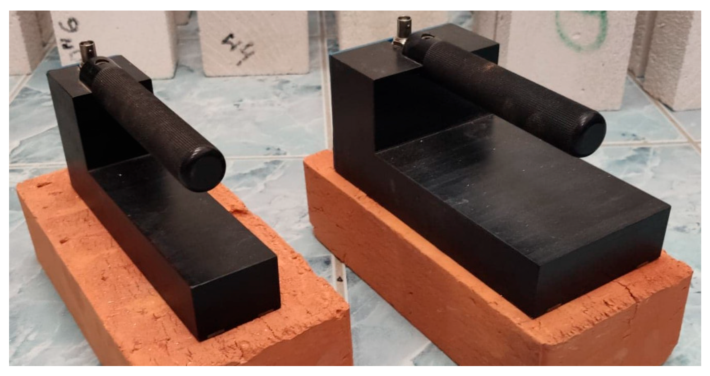
2.2. Time Domain Reflectometry Measuring Setup

For the time domain reflectometry tests, the following elements were utilized: LOM TDR multimeter (ETest, Lublin, Poland), PC computer as controlling station and for data acquisition, as well as TDR surface sensors of own design connected with the TDR multimeter by a coaxial cable. Both applied TDR sensors are widely presented in authors’ article [56] and they differ in measuring waveguides spacing, where one (Sensor A) has the distance between them equal 40 mm and the other (Sensor B) 80 mm. Both sensors are made of the polyoxymethylene having apparent permittivity value equal 3.8. Waveguides are made of brass plate bars, 10 × 2 mm in dimension and 200 mm long, that are soldered to a two-line printed circuit which connects them to BNC con-nector for coaxial cable. Figure 2 presents the photographs of both sensors.

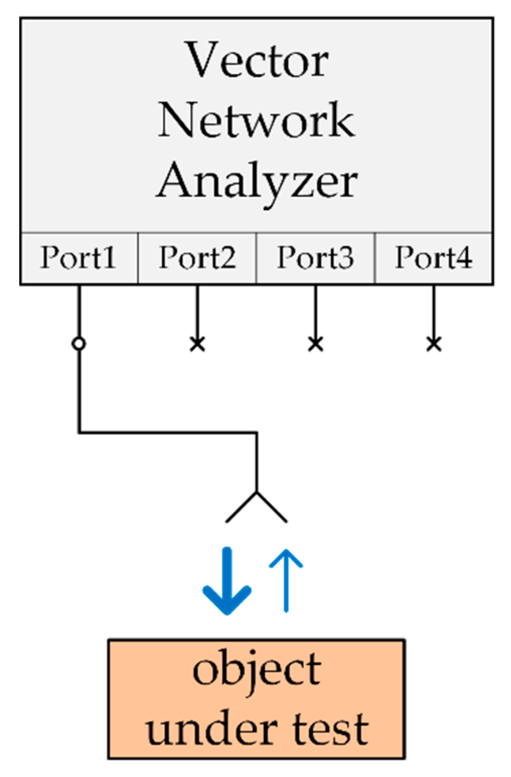
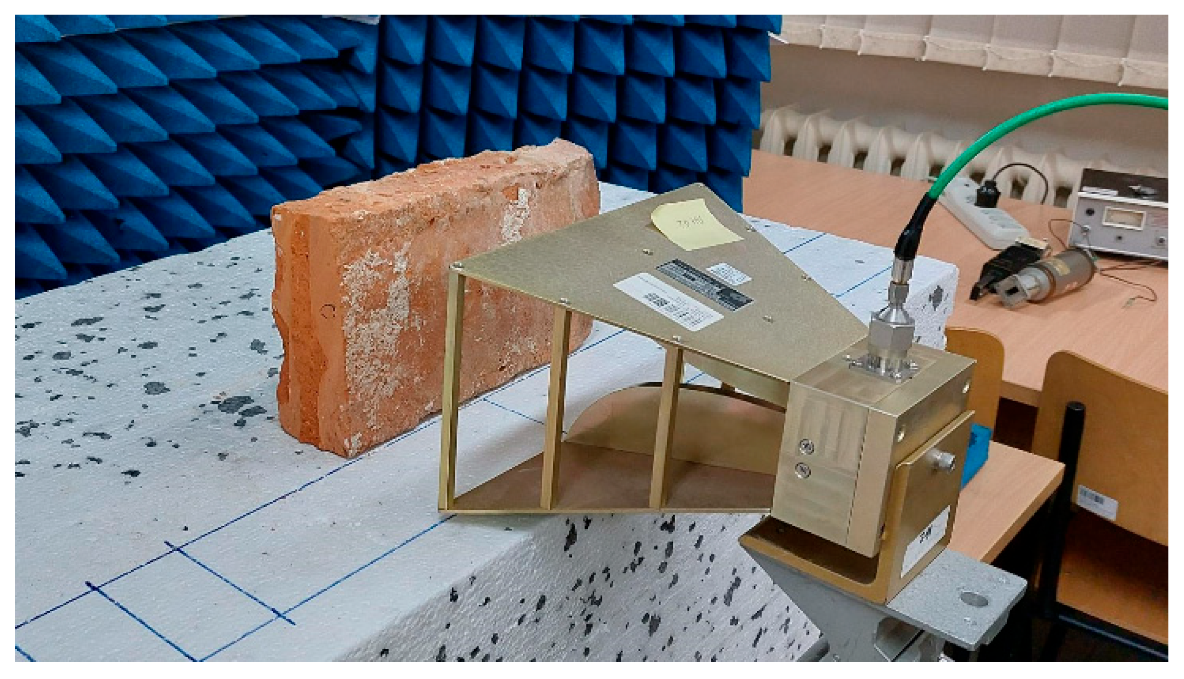
2.3. Microwave Measuring Setup

The microwave measuring setup used in this work consisted of a VNA model Agilent N5224A and a double-ridge pyramidal horn antenna. The antenna was placed at a distance of 8 cm from the sample surface. The surrounding area was covered by microwave absorbing materials in order to ensure reflection-free conditions. A picture of the measurement setup is shown in Figure 3.

2.4. Methods

2.4.1. Reflectometric Investigation

Research has been conducted under constant temperature conditions 20 ± 1 °C and air relative humidity at the level of 50%. All samples in the range of moisture between dry 0%mass and fully saturated material 14%mass were examined by two types of TDR non-invasive sensors (Sensors A and B) described in Section 2.2 which differed in width. For statistical analysis, the measurements were repeated 5 times for each sensor and material sample.

2.4.2. Microwave Investigation

Investigations of the prepared bricks with the use of microwave measuring method have been conducted according to the scheme presented in Figure 1 and the test-bed shown in Figure 3.
The VNA has been calibrated for the use of one port S11 measurements. The frequency range has been set as from 1 GHz to 11 GHz. The measurements results are in the form of complex values of reflection coefficient S11 (magnitude and angle), which are instantly recalculated by VNA to time domain. This allows visualizing the sounding wideband pulse reflected from inhomogeneities of the media along the wave propagation direction.
The main reflected peak is caused by the impedance difference between the air and the brick surface (the wave entering the brick material). The next significant peak is created by the reflection of the wave exiting the brick on the opposite side (the same boundary, material–air). The distance between these peaks in time domain carries the information of propagation time inside the brick material, the value is doubled due to round-trip propagation. As the brick thickness is known, the wave propagation velocity inside the brick material, and the real part of relative permittivity of the material, may be calculated.
The measurements of the prepared bricks have been performed for the whole brick set. For the purposes of statistical processing, all single brick measurements have been repeated 5 times.

2.5. Data Analysis Method

The results achieved with the conducted research consist of the dependences between material mass moisture of the examined material sample and apparent permittivity readouts achieved by both TDR sensors and microwave antennas.
With these results, suitable regression models were applied and measurement uncertainty evaluation was conducted according to GUM guide [GUM] [69].
For calibration, polynomial dependence was applied according to the following formula [55]:
w ^ = β 0 + β 1 · ε + β 2 · ε 2 + ϵ
where   w ^ denotes mass moisture value estimated using polynomial model [%mass], ε the apparent permittivity measured using TDR, and ϵ the random error of normal distribution.
According to many articles [63,70,71] uncertainty was expressed as root mean squared error (RMSE), which allows expressing model uncertainty and quality of model fit to the measured data.
Uncertainty evaluation covers evaluation of combined uncertainty, being the combination of two types of uncertainties: A type, i.e., the statistical uncertainty that is dependent on fitting quality of the assumed model as well as uncertainty of B type, dependent on both uncertainties and resolutions of particular devices. With the combined standard uncertainty, the expanded measuring uncertainty was estimated.
For all applied measuring methods, the B type uncertainties are significantly lower than the A type uncertainty and neglected in the calculation, so the following elements are considered for uncertainty evaluation: β0, β1, β2 estimators, and the relative permittivity (ε):
w = f β 0 , β 1 , β 2 , ε
The above-mentioned combined standard measurement uncertainty that includes both A and B type uncertainties can be described using the following formula [69,72]:
u C w = w ε u ε 2 + i = 0 2 w β i u β i 2 + 2 i = 0 2 j = i + 1 2 w β i w β j u β i , β j
so:
u c 2 w = S 2 1 + 1 n + i w β i 2 u 2 β i + 2 i j w β i w β j c o v β i β j
And the expanded uncertainty with the following formula:
U w = k p ·   u c w
where kp denotes the coverage factor that depends on the number of degrees of freedom and oscillates about 2 in value.

3. Results

Raw results achieved from both reflectometric multimeter and microwave analyzer are presented in the form of the waveforms that needed suitable interpretation to evaluate the relative permittivity value.

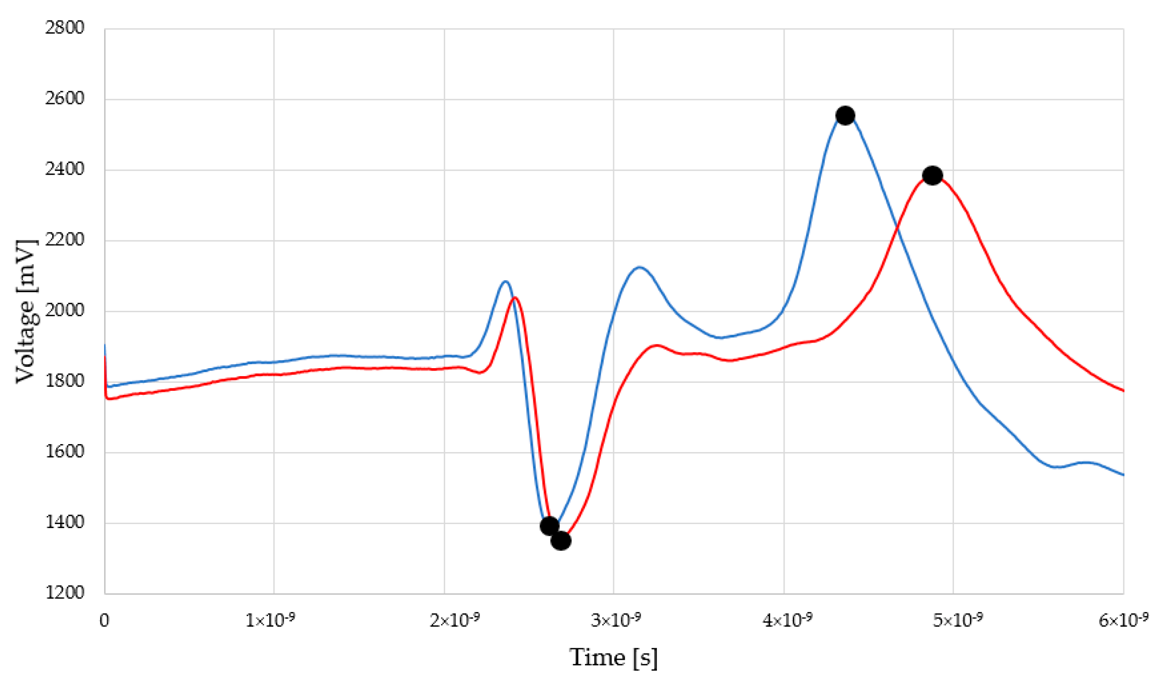
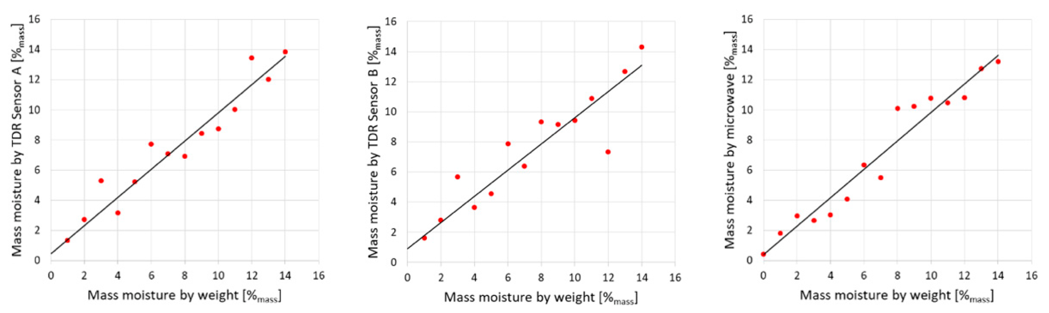
3.1. TDR Sensors Readouts

Exemplary reflectograms achieved by TDR Sensor A and Sensor B for dry and saturated status are presented in Figure 4 and Figure 5.
The peaks indicated by black dots are markers for electromagnetic pulse travel along the waveguides touching the examined material. In both figures, the first, negative one shows the entrance to the sensor (built-in resistor) and the second (positive) one, sensor termination. The position of this second peak is significant for relative permittivity evaluation. In the case of dry material (blue line), the second position is located closer to the first, negative peak. In the case of moist material (red line), second peak is located further. Within the measurement, a set of the TDR waveforms was collected and the distances between markers were recalculated into the relative permittivity values according to the Equation (2). Figure 6 and Figure 7 present the recalculated times of signal propagation into relative permittivity values for different material humidity, showing the relations between red brick mass moisture and relative permittivity values, whereas dashed lines mean confidence intervals. Red dots represent the mean values of the five relative permittivity readouts for each material moisture content.

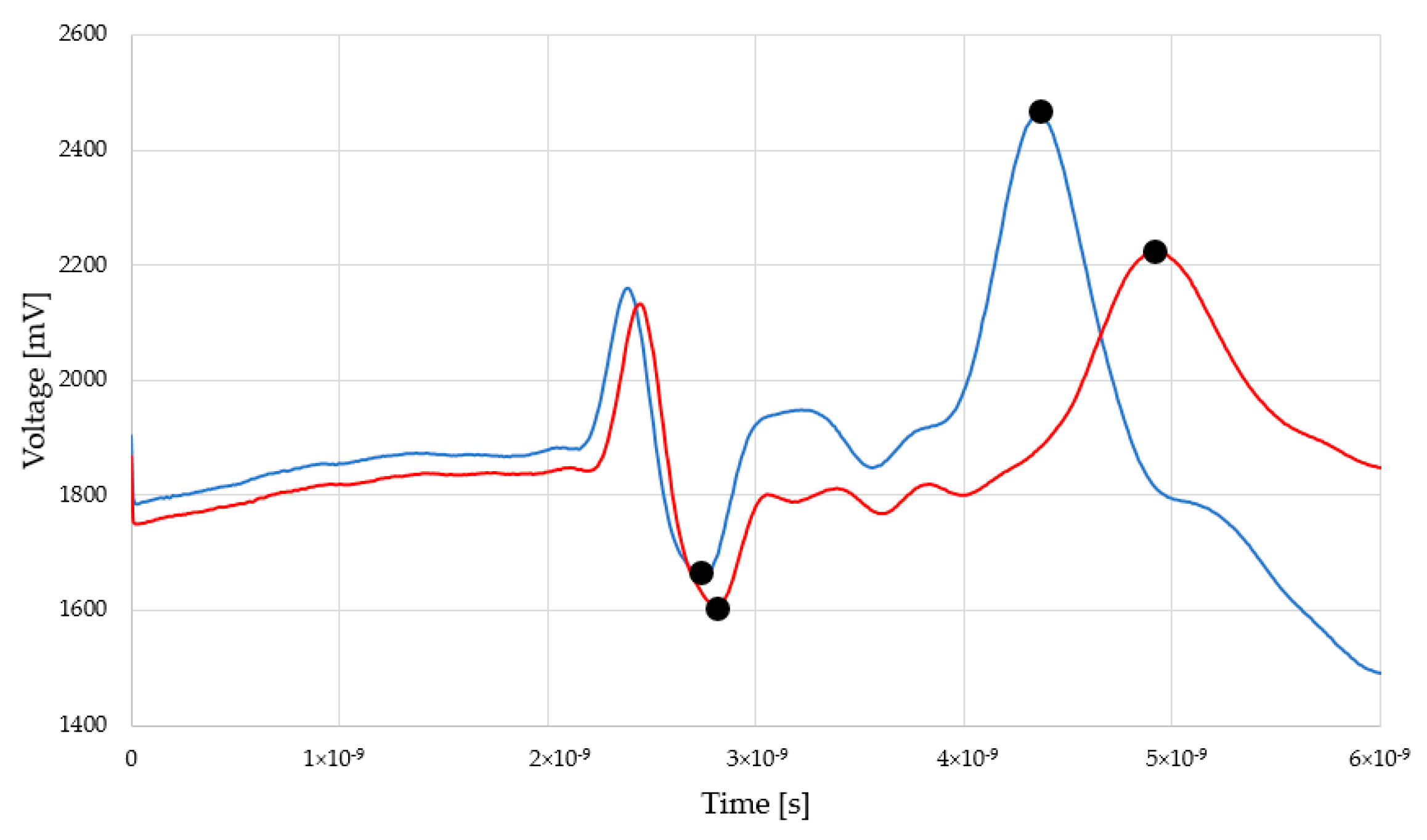
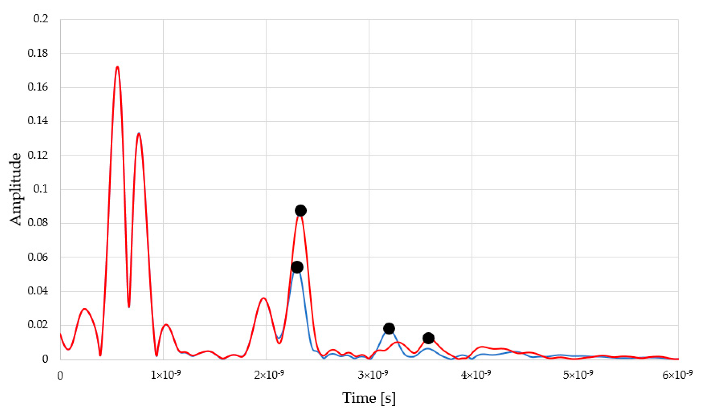
3.2. Microwave Readouts

Similarly to reflectometric readouts, the waveforms achieved from microwave measurement are presented in Figure 8.
The positive peaks highlighted by using black dots are the markers for electromagnetic pulse travel. This time, the first peak is the reflection from the first brick surface and the second peak represents the back of the material. The first peaks are located more or less in a similar position. In turn, the second peaks are shifted towards the right, depending on the moisture status of the material. In the case of moist material (9%mass), the second peak is shifted towards the right, compared to drier brick (3%mass). The two peaks below 1ns are associated with the pulse response of the antenna structure and do not influence the measurement of a distant object. Figure 9 presents the relation between red brick mass moisture and the relative permittivity values derived from measurements.

4. Discussion

With the data obtained using reflectometry and microwave measurements, some dependencies have been found and described with empirical second order polynomial regression formulas.

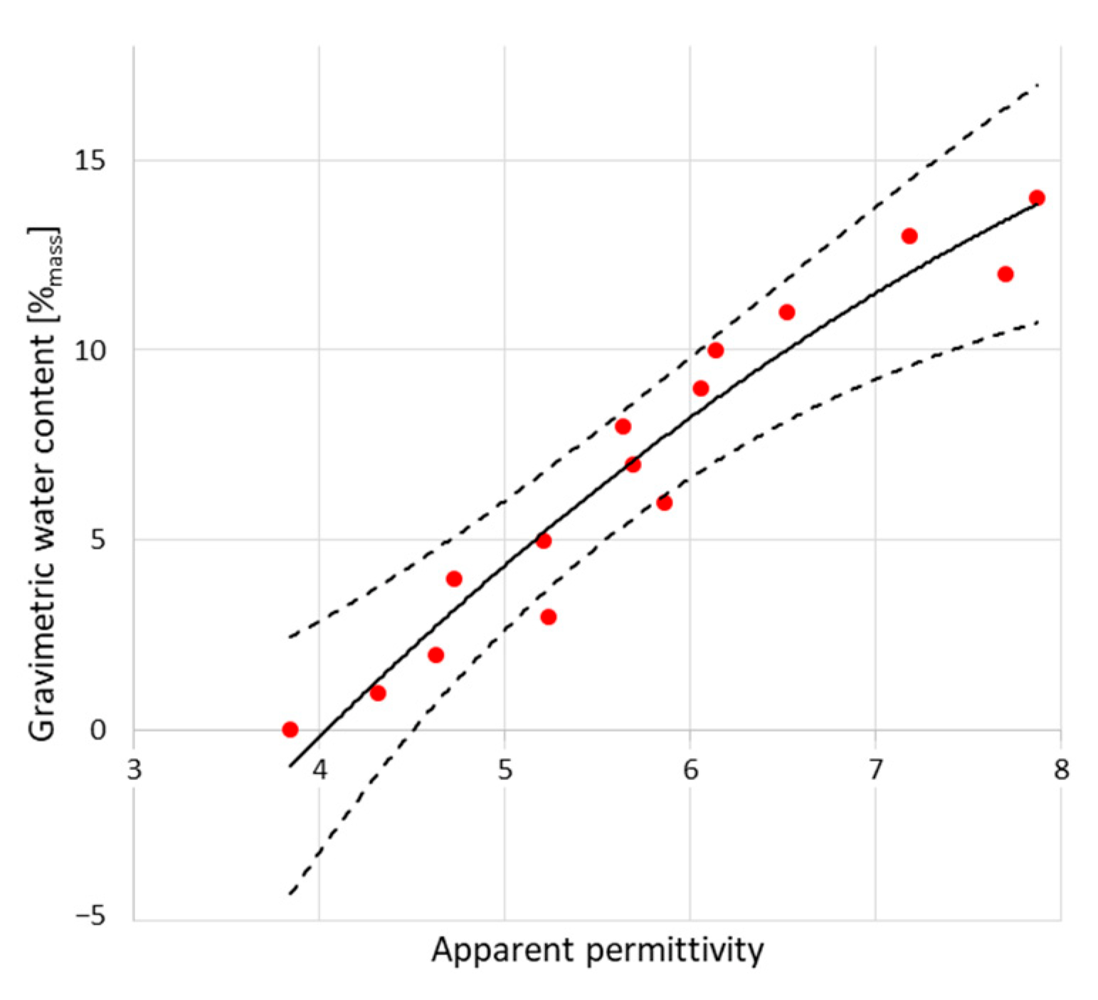
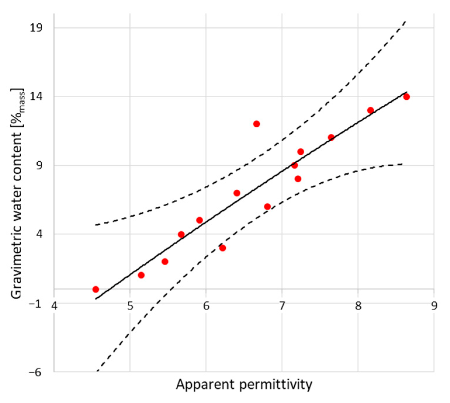
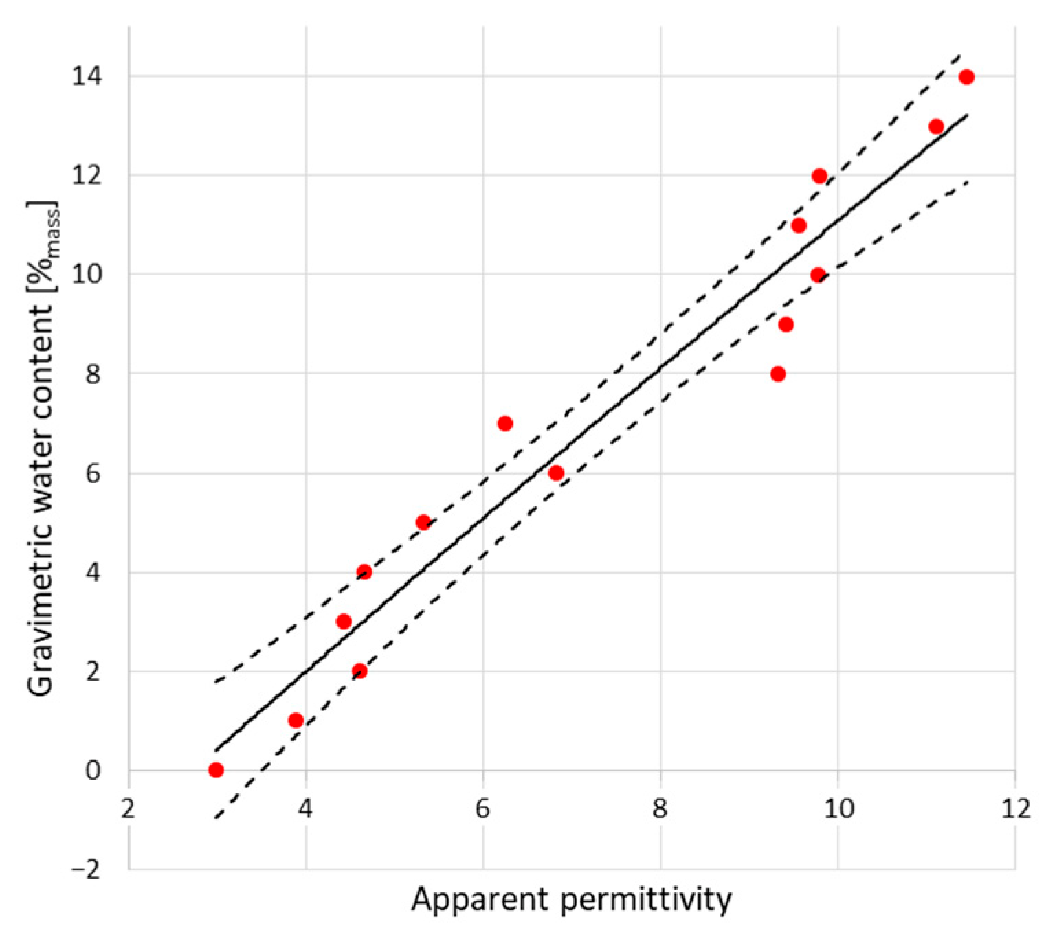
4.1. Regression Models

In the case of both TDR sensors and microwave antenna, together with the moisture increase, a relative permittivity increase is noticed. For dry samples, average permittivity readouts show the value of 4 in the case of TDR sensor A and 4.5 for TDR sensor B. For saturated states, the permittivity readouts are equal to 8 for sensor A and 8.5 for sensor B. In the case of the microwave antenna for dry material, the measured level of relative permittivity equaled about 3, while the readouts of moist material provided the relative permittivity values equal to 14. These differences could be attributed to the construction of the sensors. The relative permittivity read by the non-invasive sensors is an averaged value of the relative permittivity of the measured material, but also the sensor cover that is made of polyoxymethylene having relative permittivity constant in value, equal to 3.8 [35]. In the case of the microwave antenna sensor, the signal travels free space and totally penetrates the moist material and the second marker comes from the end of the brick, rather than the end of antenna, which provides more reliable readouts of brick moisture. Moreover, it must be emphasized that the range of TDR signal penetration for the applied sensors equals about 4–5 cm, which was evaluated in the following reference [56]. The values of relative permittivity measured for dry bricks could be compared to those found in the literature, both for microwave antenna and the TDR investigations. According to Pinhasi et al. [73], the value of dry red brick real permittivity equals 3.3 and the brick wall permittivity equals 3.56. Choroszucho et al. [74] stated that the value of dry brick permittivity equals 4.4, while Kaiser et al. [75] evaluated the permittivity of red brick at the level of 4.1. A comparison of relative permittivity of moist bricks is hindered by the different water absorptivity of materials. Nevertheless, it could be stated that this value differs between 15 and 20, depending on material type [76,77], and is higher than the one achieved in this investigation.
Table 2 presents the regression models achieved for all tested sensors (TDR Sensor A,B and microwave antenna) together with the coefficient of determination (R2), residual error (RSE), root mean square error (RMSE), and F statistics.
The assumed model of the relation between gravimetric water content and relative permittivity values based on second degree polynomial fit is satisfactory for both TDR and microwave sensors. The calibration models presented in Table 2 describe the relation between both measured values as of good quality, which is confirmed by high values of the coefficients of determination (R2) that exceed the value of 0.90 in two cases; only in the case of TDR sensor B, it equals 0.87. The best values were achieved by microwave antenna sensor (nearly 0.95), but TDR A sensor is not significantly worse (R2 of about 0.94). These high values of R2 mean that only about of 5% of the estimated value of gravimetric water content w ^ is not properly described by the assumed model.
The values of RSE (residual standard error) vary between 1.12 and 1.76%mass. The smallest value is noticed for microwave antenna sensor, whereas the highest one is the TDR, wide sensor B. The RMSE (root mean square error) values, being a popular measure of the uncertainty, range here between 1.00 and 1.57%mass, depending on the sensor applied. The lowest and the best values are again noticed for the microwave antenna, and the highest for TDR Sensor B. Similar to the RSE coefficient, the RMSE values found in literature are mostly expressed in volumetric water content (%vol or cm3/cm3) which hinders the comparison of these numbers. Nevertheless, it can be noticed that those values are comparable in value or sometimes lower than those found in the literature concerning electric moisture measurement techniques. The RMSE values achieved by Ju et al. [78] utilizing the Topp’s [34] dependence between relative permittivity and material moisture vary between 1 and 6.6%vol. In another research, presented by Roth et al. [70], the RMSE values equaled 0.8–3.7%vol, depending on material. The calibration method proposed by Malicki’s [63] enabled to achieve the RMSE values at the level of about 3%vol. Cubic polynomial model by Byun et al. [79] provided the RMSE values between 4 and 5%vol, depending on the material. Moreover, it should be emphasized that the RMSE values achieved by the tested TDR and microwave sensors are developed precisely for the examined material and particular sensor specimen. In the previously cited research, the applied models are universal and, in many cases, may not influence some characteristic data. When the achieved RMSE values are compared to those in the research presented by Udawatta et al. [64], with developed individual models for moisture evaluation by the invasive TDR probes, it can be noticed that RMSE varied in the range of 0.8–3.4%vol. In most cases, they were lower than the RMSE values established for the flat surface sensors. It is interesting that Domínguez-Niño et al. [80] conducted research in which they compared the RMSE values for the universal models, but also specific for particular sensors and materials, and achieved the RMSE values for the specific models at very low level (between 0.5 and 1%vol) as well as between 0.9 and 1.5%vol for typical, universal models applied for moisture evaluation. Those values are comparable to the RMSE values achieved in the research presented in this article. At the end, it should be noticed that the RMSE values characterizing the methods and sensors presented in this research could be compared to the another research by the co-authors of this article (Suchorab et al.) [55] where the RMSE values ranged between 2.4 and 3.2%vol for simplified sensors construction.
Figure 10 presents the results achieved from applied regression models evaluated for all sensors and the gravimetric evaluation. Linear dependences are presented in Table 3.
The dependence between the gravimetrically determined moisture (w) and TDR/microwave evaluated moisture value w ^ is clearly linear, which is visible in the diagrams presented in Figure 10. In all cases, the slope values ranged between 0.868 (the worst, for TDR Sensor B) and 0.946 (microwave antenna sensor, the best). The slope values are smaller compared to other studies by the co-authors of this paper [36,55] that were conducted using TDR A sensor specimen, but for a different material (aerated concrete), obtaining 0.994, and other non-invasive sensors which achieved the slope values between 0.988–0.993.

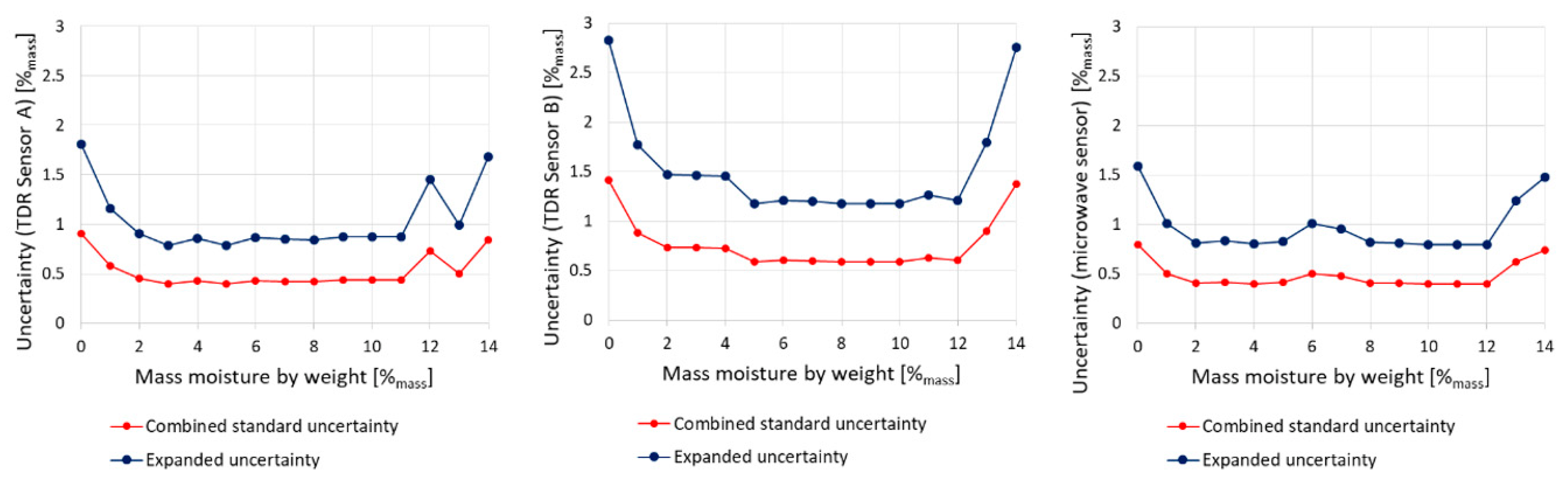
4.2. Uncertainty Evaluation

The detailed uncertainty analysis covers the evaluation of the combined standard uncertainty and complex uncertainty in relation to brick moisture. The results are presented graphically in Figure 11.
From the diagrams presented in Figure 11, it can be noticed that both types of uncertainty vary depending on the moisture status. The lowest values of uncertainty are observed for intermediate moisture states (between 2 and 12%mass). Under nearly dry or saturated conditions, those values are the highest. These variations are typical for most measuring devices and here they are mainly caused by the type of the applied regression models for calibration [36]. The lowest values have been noticed for both types of sensors. In intermediate states of moisture, expanded uncertainty amounts to about 0.8–1.0%mass, while for TDR Sensor B it ranges between 1.1–1.5%mass. In dry and wet states, expanded uncertainty is higher than 1.5%mass for both microwave antenna and TDR Sensor A and even 2.8%mass for TDR Sensor B, which is of lower quality.
While comparing the achieved results of uncertainty evaluation, it should be emphasized that they are similar or better than those found in the literature, where they vary between 1 and 4%vol, depending on the material and sensing technique. According to Černý [58], TDR uncertainty for moisture evaluation of building materials equals 2.69%vol, but Ju et al. [78] evaluated the reflectometric method uncertainty at the level of 4.0%vol. In turn, according to Roth et al. [70], the uncertainty value is between 1.1 and 1.3%vol, whereas Malicki et al. [63] reported the values between 0.4–1.8%vol. Comparing to own previous research, it must be mentioned that the TDR Sensor A used in [36] reached the uncertainty level of 1.0%vol for moderate values of moisture, while for dry and nearly saturated states, it was equal to even 2.0%vol. In the case of another construction of non-invasive TDR sensors presented in [55], the uncertainty values were higher and reached about 1.5%vol in intermediate states and even more than 3%vol for wet states.
The microwave measurements in this research have been performed with the use of broadband double-ridge horn antenna, which is a kind of “laboratory standard”. In order to implement this method in the real design, it seems necessary to develop a compact antenna with appropriate broad frequency bandwidth and high gain. For this purpose, it may be valuable to implement a kind of metamaterial technology, as shown in the exemplary references [81,82]. This approach would improve the performance of both microwave antennas and TDR sensors.
The values of the expanded uncertainty characterizing the microwave antenna as well as both TDR sensors are similar or lower comparing to other, invasive and non-invasive sensors. Nevertheless, it has to be mentioned that most of these devices perform according to universal calibration approach, while the measurements could be disturbed by unconsidered factors, such as material porosity or chemical composition of the solid phase. Such beneficial values of this parameter are mainly obtained by the individual calibration of each sensor that covers the influences of the construction differences and material characteristics.

5. Conclusions

The research on the microwave antenna and two non-invasive TDR sensors presented in this article proves that these techniques could be applied in non-invasive determination of moisture states of the porous building materials. To achieve the satisfactory level of applicability, all proposed sensors demand individual calibration for each sensor design as well as material type. This is mainly caused by the structure of porous building materials that may differ in porosity, absorptivity, or bulk density as well as the chemical compound of the solid phase. Contrary to the universal calibration models, individual calibration covers material differences and thus positively influences the value of measurement uncertainty.
Among the tested sensors, the microwave antenna sensor is characterized by the most beneficial measuring parameters, including the RMSE value for calibration formula equal to 1.00%mass and expanded measuring uncertainty in intermediate moisture states in the range of 0.8–1.0%mass. Non-invasive TDR Sensor A, presented previously in another research, has the RMSE value equal to 1.09%mass and expanded uncertainty in intermediate moisture states comparable to the microwave antenna sensor. The worst measured parameters were achieved by TDR Sensor B with RMSE equal to 1.57%mass and expanded uncertainty reaching 1.5%mass.
Nevertheless, it should be emphasized that all tested sensors provide satisfactory measuring features compared to other, even invasive sensors that are not individually calibrated for particular sensor construction or material.
All of the applied sensors are prospective for non-invasive masonry moisture evaluation, but it should be remembered that both TDR sensors are designed for surface testing and enable to detect condensation moisture in the surface layers of the masonry. In turn, microwave antenna enables penetration across the total thickness of the brick or even entire masonry thickness and enables detection of interior masonry moisture, even capillary water.

Author Contributions

Conceptualization, Z.S. (Zbigniew Suchorab), K.T. and Z.S. (Zenon Szczepaniak); methodology, Z.S. (Zbigniew Suchorab), W.S. and Z.S. (Zenon Szczepaniak); software, Z.S. (Zbigniew Suchorab) and T.R.; validation, Z.S. (Zbigniew Suchorab), T.R. and Z.S. (Zenon Szczepaniak); formal analysis, Z.S. (Zbigniew Suchorab) and Z.S. (Zenon Szczepaniak); investigation, P.B., T.R. and G.Ł.; resources, K.T.; data curation, Z.S. (Zbigniew Suchorab), Z.S. (Zenon Szczepaniak) and T.R.; writing—original draft preparation, Z.S. (Zbigniew Suchorab) and Z.S. (Zenon Szczepaniak); writing—review and editing, P.B. and G.Ł.; visualization, Z.S. (Zbigniew Suchorab); supervision, Z.S. (Zbigniew Suchorab) and K.T.; project administration, Z.S. (Zbigniew Suchorab) and K.T.; funding acquisition, K.T. All authors have read and agreed to the published version of the manuscript.

Funding

This research was funded by Polish National Centre for Research and Development, grant number POIR.01.01.01-00-1014/19.

Institutional Review Board Statement

Not applicable.

Informed Consent Statement

Not applicable.

Data Availability Statement

Data are contained within the article.

Conflicts of Interest

The authors declare no conflict of interests.

References

  1. Zhou, X.; Derome, D.; Carmeliet, J. Analysis of Moisture Risk in Internally Insulated Masonry Walls. Build. Environ. 2022, 212, 108734. [Google Scholar] [CrossRef]
  2. Hoła, A.; Matkowski, Z.; Hoła, J. Analysis of the Moisture Content of Masonry Walls in Historical Buildings Using the Basement of a Medieval Town Hall as an Example. Procedia Eng. 2017, 172, 363–368. [Google Scholar] [CrossRef]
  3. Vereecken, E.; Roels, S. Hygric Performance of a Massive Masonry Wall: How Do the Mortar Joints Influence the Moisture Flux? Constr. Build. Mater. 2013, 41, 697–707. [Google Scholar] [CrossRef]
  4. Yousuf, H.; Al-Kheetan, M.J.; Rahman, M.M.; Ghaffar, S.H.; Braimah, N.; Chamberlain, D.A. Introducing a Novel Concept of Wick Drainage in Masonry Structures. J. Build. Eng. 2022, 51, 104332. [Google Scholar] [CrossRef]
  5. Litavcova, E.; Korjenic, A.; Korjenic, S.; Pavlus, M.; Sarhadov, I.; Seman, J.; Bednar, T. Diffusion of Moisture into Building Materials: A Model for Moisture Transport. Energy Build. 2014, 68, 558–561. [Google Scholar] [CrossRef]
  6. Korjenic, A.; Bednar, T. An Analytical Solution of a Moisture Transfer Problem for Coupled Room and Building Component. Energy Build. 2012, 47, 254–259. [Google Scholar] [CrossRef]
  7. Suchorab, Z.; Barnat-Hunek, D.; Sobczuk, H. Influence of Moisture on Heat Conductivity of Aerated Concrete. Ecol. Chem. Eng. S 2011, 18, 111–120. [Google Scholar]
  8. Brzyski, P.; Barnat-Hunek, D.; Suchorab, Z.; Łagód, G. Composite Materials Based on Hemp and Flax for Low-Energy Buildings. Materials 2017, 10, 510. [Google Scholar] [CrossRef]
  9. Życzyńska, A. The Heat Consumption and Heating Costs after the Insulation of Building Partitions of Building Complex Supplied by the Local Oil Boiler Room. Eksploat. Niezawodn. 2014, 16, 313–318. [Google Scholar]
  10. Rirsch, E.; Zhang, Z. Rising Damp in Masonry Walls and the Importance of Mortar Properties. Constr. Build. Mater. 2010, 24, 1815–1820. [Google Scholar] [CrossRef]
  11. Franzoni, E.; Bandini, S. Spontaneous Electrical Effects in Masonry Affected by Capillary Water Rise: The Role of Salts. Constr. Build. Mater. 2012, 35, 642–646. [Google Scholar] [CrossRef]
  12. Orr, S.A.; Fusade, L.; Young, M.; Stelfox, D.; Leslie, A.; Curran, J.; Viles, H. Moisture Monitoring of Stone Masonry: A Comparison of Microwave and Radar on a Granite Wall and a Sandstone Tower. J. Cult. Herit. 2020, 41, 61–73. [Google Scholar] [CrossRef]
  13. Li, Y.; Kong, Z.; Xie, H.; Ma, Y.; Mu, B.; Hokoi, S. Construction Type Influences Features of Rising Damp of Blue-Brick Masonry Walls. Constr. Build. Mater. 2021, 284, 122791. [Google Scholar] [CrossRef]
  14. Llorente-Alvarez, A.; Camino-Olea, M.S.; Cabeza-Prieto, A.; Saez-Perez, M.P.; Rodríguez-Esteban, M.A. The Thermal Conductivity of the Masonry of Handmade Brick Cultural Heritage with Respect to Density and Humidity. J. Cult. Herit. 2022, 53, 212–219. [Google Scholar] [CrossRef]
  15. Yedra, E.; Ferrández, D.; Morón, C.; Saiz, P. New Test Methods to Determine Water Absorption by Capillarity. Experimental Study in Masonry Mortars. Constr. Build. Mater. 2022, 319, 125988. [Google Scholar] [CrossRef]
  16. Suchorab, Z.; Frąc, M.; Guz, Ł.; Oszust, K.; Łagód, G.; Gryta, A.; Bilińska-Wielgus, N.; Czerwiński, J. A Method for Early Detection and Identification of Fungal Contamination of Building Materials Using E-Nose. PLoS ONE 2019, 14, e0215179. [Google Scholar] [CrossRef] [Green Version]
  17. Matsumoto, M.; Hokoi, S.; Hatano, M. Model for Simulation of Freezing and Thawing Processes in Building Materials. Build. Environ. 2001, 36, 733–742. [Google Scholar] [CrossRef]
  18. Wardeh, G.; Perrin, B. Freezing–Thawing Phenomena in Fired Clay Materials and Consequences on Their Durability. Constr. Build. Mater. 2008, 22, 820–828. [Google Scholar] [CrossRef]
  19. Barnat-Hunek, D.; Smarzewski, P.; Suchorab, Z. Effect of Hydrophobisation on Durability Related Properties of Ceramic Brick. Constr. Build. Mater. 2016, 111, 275–285. [Google Scholar] [CrossRef]
  20. Voutilainen, J. Methods and Instrumentation for Measuring Moisture in Building Structures; Helsinki University of Technology: Espoo, Finland, 2005. [Google Scholar]
  21. Ramirez, R.; Ghiassi, B.; Pineda, P.; Lourenço, P.B. Experimental Characterization of Moisture Transport in Brick Masonry with Natural Hydraulic Lime Mortar. Build. Environ. 2021, 205, 108256. [Google Scholar] [CrossRef]
  22. Linnow, K.; Halsberghe, L.; Steiger, M. Analysis of Calcium Acetate Efflorescences Formed on Ceramic Tiles in a Museum Environment. J. Cult. Herit. 2007, 8, 44–52. [Google Scholar] [CrossRef]
  23. Andrés, A.; Díaz, M.C.; Coz, A.; Abellán, M.J.; Viguri, J.R. Physico-Chemical Characterisation of Bricks All through the Manufacture Process in Relation to Efflorescence Salts. J. Eur. Ceram. Soc. 2009, 29, 1869–1877. [Google Scholar] [CrossRef]
  24. Morillas, H.; Maguregui, M.; Trebolazabala, J.; Madariaga, J.M. Nature and Origin of White Efflorescence on Bricks, Artificial Stones, and Joint Mortars of Modern Houses Evaluated by Portable Raman Spectroscopy and Laboratory Analyses. Spectrochim. Acta Part A Mol. Biomol. Spectrosc. 2015, 136, 1195–1203. [Google Scholar] [CrossRef] [PubMed]
  25. Nilsson, L.-O. Hygroscopic Moisture in Concrete-Drying, Measurements & Related Material Properties; Lund University: Lund, Sweden, 1980. [Google Scholar]
  26. Oliver, A.C. Dampness in Buildings, 2nd ed.; Blackwell Science Ltd.: Cambridge, MA, USA; London, UK, 1997. [Google Scholar]
  27. Kuske, M.; Romain, A.-C.; Nicolas, J. Microbial Volatile Organic Compounds as Indicators of Fungi. Can an Electronic Nose Detect Fungi in Indoor Environments? Build. Environ. 2005, 40, 824–831. [Google Scholar] [CrossRef] [Green Version]
  28. Kuske, M.; Rubio, R.; Romain, A.C.; Nicolas, J.; Marco, S. Fuzzy K-NN Applied to Moulds Detection. Sens. Actuators B Chem. 2005, 106, 52–60. [Google Scholar] [CrossRef] [Green Version]
  29. Malec, A.; Garbacz, M.; Klimek, B.; Guz, Ł.; Golianek, P.; Suchorab, Z. Damages Caused by Microorganisms in Historical Buildings on the Example of a Multi-Family Residential Building. Int. J. Conserv. Sci. 2021, 12, 805–816. [Google Scholar]
  30. Połednik, B. Variations in Particle Concentrations and Indoor Air Parameters in Classrooms in the Heating and Summer Seasons. Arch. Environ. Prot. 2013, 39, 15–28. [Google Scholar] [CrossRef] [Green Version]
  31. Morath, S.U.; Hung, R.; Bennett, J.W. Fungal Volatile Organic Compounds: A Review with Emphasis on Their Biotechnological Potential. Fungal Biol. Rev. 2012, 26, 73–83. [Google Scholar] [CrossRef]
  32. Robert, A. Dielectric Permittivity of Concrete between 50 Mhz and 1 Ghz and GPR Measurements for Building Materials Evaluation. J. Appl. Geophys. 1998, 40, 89–94. [Google Scholar] [CrossRef]
  33. Freitas, T.S.; Guimarães, A.S.; Roels, S.; Peixoto de Freitas, V.; Cataldo, A. Is the Time-Domain Reflectometry (TDR) Technique Suitable for Moisture Content Measurement in Low-Porosity Building Materials? Sustainability 2020, 12, 7855. [Google Scholar] [CrossRef]
  34. Topp, G.C.; Davis, J.L.; Annan, A.P. Electromagnetic Determination of Soil Water Content: Measurements in Coaxial Transmission Lines. Water Resour. Res. 1980, 16, 574–582. [Google Scholar] [CrossRef] [Green Version]
  35. Skierucha, W.; Wilczek, A.; Alokhina, O. Calibration of a TDR Probe for Low Soil Water Content Measurements. Sens. Actuators A Phys. 2008, 147, 544–552. [Google Scholar] [CrossRef]
  36. Suchorab, Z.; Widomski, M.; Łagód, G.; Barnat-Hunek, D.; Majerek, D. A Noninvasive TDR Sensor to Measure the Moisture Content of Rigid Porous Materials. Sensors 2018, 18, 3935. [Google Scholar] [CrossRef] [PubMed] [Green Version]
  37. Davis, J.L.; Annan, A.P. Ground-Penetrating Radar for High-Resolution Mapping of Soil and Rock Stratigraphy1. Geophys. Prospect. 1989, 37, 531–551. [Google Scholar] [CrossRef]
  38. Daniels, D.J. Surface-Penetrating Radar (IEE Radar, Sonar, Navigation and Avionics Series 6); Institute of Engineering & Technology: London, UK, 1996; ISBN 0852968620. [Google Scholar]
  39. Korhonen, C.J.; Janoo, V.C.; Berini, C.M. Time-Domain Reflectometry of Water Content in Portland Cement Concrete; Cold Regions Research & Engineering Laboratory: Hanover, NH, USA, 1997. [Google Scholar]
  40. Mohamed, A.M.O. Principles and Applications of Time Domain Electrometry in Geoenvi-Ronmental Engineering; CRC Press: Boca Raton, FL, USA, 2006. [Google Scholar]
  41. Skierucha, W.; Malicki, M.A. TDR Method for the Measurement of Water Content and Salinity of Porous Media; Institute of Agrophysics, Polish Academy of Sciences: Lublin, Poland, 2004. [Google Scholar]
  42. Wilczek, A.; Szypłowska, A.; Kafarski, M.; Skierucha, W. A Time-Domain Reflectometry Method with Variable Needle Pulse Width for Measuring the Dielectric Properties of Materials. Sensors 2016, 16, 191. [Google Scholar] [CrossRef] [Green Version]
  43. Velez, P.; Grenier, K.; Mata-Contreras, J.; Dubuc, D.; Martin, F. Highly-Sensitive Microwave Sensors Based on Open Complementary Split Ring Resonators (OCSRRs) for Dielectric Characterization and Solute Concentration Measurement in Liquids. IEEE Access 2018, 6, 48324–48338. [Google Scholar] [CrossRef]
  44. Wei, Z.; Huang, J.; Li, J.; Xu, G.; Ju, Z.; Liu, X.; Ni, X. A High-Sensitivity Microfluidic Sensor Based on a Substrate Integrated Waveguide Re-Entrant Cavity for Complex Permittivity Measurement of Liquids. Sensors 2018, 18, 4005. [Google Scholar] [CrossRef] [Green Version]
  45. Hao, H.; Wang, D.; Wang, Z.; Yin, B.; Ruan, W. Design of a High Sensitivity Microwave Sensor for Liquid Dielectric Constant Measurement. Sensors 2020, 20, 5598. [Google Scholar] [CrossRef]
  46. Oliveira, J.G.D.; Junior, J.G.D.; Pinto, E.N.M.G.; Neto, V.P.S.; D’Assunção, A.G. A New Planar Microwave Sensor for Building Materials Complex Permittivity Characterization. Sensors 2020, 20, 6328. [Google Scholar] [CrossRef]
  47. Jones, S.B.; Wraith, J.M.; Or, D. Time Domain Reflectometry Measurement Principles and Applications. Hydrol. Process. 2002, 16, 141–153. [Google Scholar] [CrossRef]
  48. Noborio, K. Measurement of Soil Water Content and Electrical Conductivity by Time Domain Reflectometry: A Review. Comput. Electron. Agric. 2001, 31, 213–237. [Google Scholar] [CrossRef]
  49. He, H.; Aogu, K.; Li, M.; Xu, J.; Sheng, W.; Jones, S.B.; González-Teruel, J.D.; Robinson, D.A.; Horton, R.; Bristow, K.; et al. A Review of Time Domain Reflectometry (TDR) Applications in Porous Media. In Advances in Agronomy; Elsevier: Amsterdam, The Netherlands, 2021; Volume 168, pp. 83–155. ISBN 978-0-12-824589-7. [Google Scholar]
  50. Majcher, J.; Kafarski, M.; Wilczek, A.; Szypłowska, A.; Lewandowski, A.; Woszczyk, A.; Skierucha, W. Application of a Dagger Probe for Soil Dielectric Permittivity Measurement by TDR. Measurement 2021, 178, 109368. [Google Scholar] [CrossRef]
  51. Selker, J.S.; Graff, L.; Steenhuis, T. Noninvasive Time Domain Reflectometry Moisture Measurement Probe. Soil Sci. Soc. Am. J. 1993, 57, 934–936. [Google Scholar] [CrossRef]
  52. Persson, M.; Berndtsson, R. Noninvasive Water Content and Electrical Conductivity Laboratory Measurements Using Time Domain Reflectometry. Soil Sci. Soc. Am. J. 1998, 62, 1471–1476. [Google Scholar] [CrossRef]
  53. Wraith, J.M.; Robinson, D.A.; Jones, S.B.; Long, D.S. Spatially Characterizing Apparent Electrical Conductivity and Water Content of Surface Soils with Time Domain Reflectometry. Comput. Electron. Agric. 2005, 46, 239–261. [Google Scholar] [CrossRef]
  54. Choi, C.; Song, M.; Kim, D.; Yu, X. A New Non-Destructive TDR System Combined with a Piezoelectric Stack for Measuring Properties of Geomaterials. Materials 2016, 9, 439. [Google Scholar] [CrossRef] [PubMed] [Green Version]
  55. Suchorab, Z.; Majerek, D.; Kočí, V.; Černý, R. Time Domain Reflectometry Flat Sensor for Non-Invasive Monitoring of Moisture Changes in Building Materials. Measurement 2020, 165, 108091. [Google Scholar] [CrossRef]
  56. Suchorab, Z.; Malec, A.; Sobczuk, H.; Łagód, G.; Gorgol, I.; Łazuka, E.; Brzyski, P.; Trník, A. Determination of Time Domain Reflectometry Surface Sensors Sensitivity Depending on Geometry and Material Moisture. Sensors 2022, 22, 735. [Google Scholar] [CrossRef]
  57. Malicki, M.A.; Skierucha, W.M. A Manually Controlled TDR Soil Moisture Meter Operating with 300 Ps Rise-Time Needle Pulse. Irrig. Sci. 1989, 10, 153–163. [Google Scholar] [CrossRef]
  58. Černý, R. Time-Domain Reflectometry Method and Its Application for Measuring Moisture Content in Porous Materials: A Review. Measurement 2009, 42, 329–336. [Google Scholar] [CrossRef]
  59. Loor, G.P. de Dielectric Properties of Heterogeneous Mixtures Containing Water. J. Microw. Power 1968, 3, 67–73. [Google Scholar] [CrossRef]
  60. Dobson, M.; Ulaby, F.; Hallikainen, M.; El-rayes, M. Microwave Dielectric Behavior of Wet Soil-Part II: Dielectric Mixing Models. IEEE Trans. Geosci. Remote Sens. 1985, 23, 35–46. [Google Scholar] [CrossRef]
  61. Tinga, W.R.; Voss, W.A.G.; Blossey, D.F. Generalized Approach to Multiphase Dielectric Mixture Theory. J. Appl. Phys. 1973, 44, 3897–3902. [Google Scholar] [CrossRef]
  62. Szypłowska, A.; Lewandowski, A.; Yagihara, S.; Saito, H.; Furuhata, K.; Szerement, J.; Kafarski, M.; Wilczek, A.; Majcher, J.; Woszczyk, A.; et al. Dielectric Models for Moisture Determination of Soils with Variable Organic Matter Content. Geoderma 2021, 401, 115288. [Google Scholar] [CrossRef]
  63. Malicki, M.A.; Plagge, R.; Roth, C.H. Improving the Calibration of Dielectric TDR Soil Moisture Determination Taking into Account the Solid Soil. Eur. J. Soil Sci. 1996, 47, 357–366. [Google Scholar] [CrossRef]
  64. Udawatta, R.P.; Anderson, S.H.; Motavalli, P.P.; Garrett, H.E. Calibration of a Water Content Reflectometer and Soil Water Dynamics for an Agroforestry Practice. Agrofor. Syst. 2011, 82, 61–75. [Google Scholar] [CrossRef]
  65. Krupka, J.; Kopyt, P.; Czekala, P.; Salski, B.; Derzakowski, K.; Mazierska, J. Complex Permittivity of Mixtures of Sand With Aqueous NaCl Solutions Measured at 2.5 GHz. In Proceedings of the 2021 13th International Conference on Electromagnetic Wave Interaction with Water and Moist Substances (ISEMA), Kiel, Germany, 26–30 July 2021; pp. 1–3. [Google Scholar]
  66. Davis, B.; Grosvenor, C.; Johnk, R.; Novotny, D.; Baker-Jarvis, J.; Janezic, M. Complex Permittivity of Planar Building Materials Measured with an Ultra-Wideband Free-Field Antenna Measurement System. J. Res. Natl. Inst. Stand. Technol. 2007, 112, 67. [Google Scholar] [CrossRef]
  67. Horsley, A.; Thaler, D.S. Microwave Detection and Quantification of Water Hidden in and on Building Materials: Implications for Healthy Buildings and Microbiome Studies. BMC Infect. Dis. 2019, 19, 67. [Google Scholar] [CrossRef]
  68. O’Connor, K.M.; Dowding, C.H. Geomeasurements by Pulsing TDR Cables and Probes; First Issued in Paperback; CRC Press: Boca Raton, FL, USA, 2019; ISBN 978-0-367-39997-9. [Google Scholar]
  69. BIPM; IEC; IFCC; ILAC; ISO; IUPAC; IUPAP; OIML. Guide to the Expression of Uncertainty in Measurement, JCGM 100:2008 (GUM 1995 with Minor Corrections). 2008. Available online: http://www.bipm.org/utils/common/documents/jcgm/JCGM_100_2008_E.pdf (accessed on 6 May 2022).
  70. Roth, K.; Schulin, R.; Flühler, H.; Attinger, W. Calibration of Time Domain Reflectometry for Water Content Measurement Using a Composite Dielectric Approach. Water Resour. Res. 1990, 26, 2267–2273. [Google Scholar] [CrossRef]
  71. Chai, T.; Draxler, R.R. Root Mean Square Error (RMSE) or Mean Absolute Error (MAE)?—Arguments against Avoiding RMSE in the Literature. Geosci. Model Dev. 2014, 7, 1247–1250. [Google Scholar] [CrossRef] [Green Version]
  72. Majerek, D.; Widomski, M.; Garbacz, M.; Suchorab, Z. Estimation of the Measurement Uncertainty of Humidity Using a TDR Probe. AIP Conf. Proc. 2018, 1988, 020027. [Google Scholar]
  73. Pinhasi, Y.; Yahalom, A.; Petnev, S. Propagation of Ultra Wide-Band Signals in Lossy Dispersive Media. In Proceedings of the 2008 IEEE International Conference on Microwaves, Communications, Antennas and Electronic Systems, Tel-Aviv, Israel, 13–14 May 2008; pp. 1–10. [Google Scholar]
  74. Choroszucho, A.; Butrylo, B.; Steckiewicz, A.; Stankiewicz, J.M. Determination of the Effective Electromagnetic Parameters of Complex Building Materials for Numerical Analysis of Wireless Transmission Networks. Electronics 2020, 9, 1569. [Google Scholar] [CrossRef]
  75. Kaiser, T. (Ed.) Smart Antennas-State of the Art (EURASIP Book Series on Signal Processing and Communications); Hindawi Publishing Corporation: New York, NY, USA, 2005; ISBN 978-977-5945-09-9. [Google Scholar]
  76. Binda, L. RILEM TC 177-MDT Recommendations of RILEM TC177-MDT: Masonry Durability and on-Site TestingMD.E.1 Determination of Moisture Distribution and Level Using Radar in Masonry Built with Regular Units. Mater. Struct. 2005, 38, 283–288. [Google Scholar] [CrossRef]
  77. Tesárek, P.; Pavlík, Z.; Černý, R. Comparison of the Capacitance Method and the Microwave Impulse Method for Determination of Moisture Profiles in Building Materials. Acta Polytech. Czech Tech. Univ. Prague 2005, 45, 42–47. [Google Scholar] [CrossRef]
  78. Ju, Z.; Liu, X.; Ren, T.; Hu, C. Measuring Soil Water Content With Time Domain Reflectometry: An Improved Calibration Considering Soil Bulk Density. Soil Sci. 2010, 175, 469–473. [Google Scholar] [CrossRef]
  79. Byun, Y.-H.; Hong, W.-T.; Yoon, H.-K. Characterization of Cementation Factor of Unconsolidated Granular Materials Through Time Domain Reflectometry with Variable Saturated Conditions. Materials 2019, 12, 1340. [Google Scholar] [CrossRef] [Green Version]
  80. Domínguez-Niño, J.M.; Bogena, H.R.; Huisman, J.A.; Schilling, B.; Casadesús, J. On the Accuracy of Factory-Calibrated Low-Cost Soil Water Content Sensors. Sensors 2019, 19, 3101. [Google Scholar] [CrossRef] [Green Version]
  81. Lee, D.; So, S.; Hu, G.; Kim, M.; Badloe, T.; Cho, H.; Kim, J.; Kim, H.; Qiu, C.-W.; Rho, J. Hyperbolic Metamaterials: Fusing Artificial Structures to Natural 2D Materials. eLight 2022, 2, 1–23. [Google Scholar] [CrossRef]
  82. Wang, Y.; Yuan, Y.; Yang, G.; Ding, X.; Wu, Q.; Jiang, Y.; Burokur, S.N.; Zhang, K. Perfect Control of Diffraction Patterns with Phase-Gradient Metasurfaces. ACS Appl. Mater. Interfaces 2022, 14, 16856–16865. [Google Scholar] [CrossRef]
Figure 1. General diagram of microwave measurement technique based on reflection coefficient approach.
Sensors 22 03622 g001
Figure 2. Photograph of non-invasive TDR sensors—Sensor A (left), Sensor B (right).
Sensors 22 03622 g002
Figure 3. Close up of the laboratory setup during microwave measurements: double ridge antenna, a brick, styrofoam stand and microwave absorbers.
Sensors 22 03622 g003
Figure 4. Reflectograms achieved by Sensor A for dry and moist material.
Sensors 22 03622 g004
Figure 5. Reflectograms achieved by Sensor B for dry and moist material.
Sensors 22 03622 g005
Figure 6. Dependence between relative permittivity readouts using TDR A Sensor and mass moisture evaluated gravimetrically.
Sensors 22 03622 g006
Figure 7. Dependence between relative permittivity readouts using TDR B Sensor and mass moisture evaluated gravimetrically.
Sensors 22 03622 g007
Figure 8. Exemplary waveforms achieved for 3%mass and 9%mass moist material with the use of microwave reflectance sensor.
Sensors 22 03622 g008
Figure 9. Dependence between relative permittivity readouts using microwave antenna and mass moisture evaluated gravimetrically.
Sensors 22 03622 g009
Figure 10. Dependences between material moisture evaluated gravimetrically and using various electric sensors. Red dots denote measuring points.
Sensors 22 03622 g010
Figure 11. Distribution of combined standard and expanded measurement uncertainties for red brick and all tested sensors.
Sensors 22 03622 g011
Table 1. Parameters of solid ceramic bricks adopted for testing.
Dimensions [cm]Mass in Dry State [g]Added
Water [g]
Mass after Soaking [g]Moisture Content by Mass [%]Moisture Content by Volume [%]Apparent Density [g/cm3]
25.2 × 11.9 × 5.93385.233.93419.111.91903.3
25.3 × 12.0 × 6.03332.466.63399.023.71833.0
25.2 × 12.0 × 6.13398.4102.03500.435.51842.5
25.1 × 11.9 × 6.03396.2135.83532.047.61888.3
25.4 × 12.0 × 6.13461173.13634.159.31853.9
24.9 × 11.9 × 6.03290.4197.43487.8611.11848.9
25.3 × 11.9 × 6.23374.6236.23610.8712.81822.6
25.3 × 12.0 × 6.13270.2261.63531.8814.31787.1
25.2 × 12.0 × 5.93350301.53651.5916.91877.6
25.2 × 11.9 × 6.13329.6333.03662.61018.21817.6
25.3 × 12.0 × 6.13427377.03804.01120.61874.7
25.1 × 11.9 × 6.13318398.23716.21221.91821.1
25.3 × 12.0 × 6.03410.4443.43853.81324.21858.5
25.0 × 11.9 × 6.03313.6463.93777.51426.11860.9
25.2 × 11.8 × 5.83267.2457.43724.61426.61903.5
Table 2. Calibration models for TDR A and B sensors and microwave antenna.
SensorRegression ModelR2RSE [%mass]RMSE [%mass]F Statistics
TDR—sensor Aw = −0.3088∙ε2 + 7.2882∙ε − 24.3930.9371.221.0988.821 (***) (df = 2; 12)
TDR—sensor Bw = −0.067∙ε2 + 4.5585∙ε − 20.0660.8681.761.5739.301 (***) (df = 2; 12)
Microwave antennaw = −0.0074∙ε2 + 1.6193∙ε − 4.36620.9461.121.00105.463 (***) (df = 2; 12)
*** p < 0.001 (critical level of significance).
Table 3. Relations between gravimetric water content measured gravimetrically and evaluated by indirect techniques.
SensorFormulaR2
TDR—sensor Ay = 0.9368∙x + 0.45140.937
TDR—sensor By = 0.8676∙x + 0.92720.868
Microwave antennay = 0.9463∙x + 0.37670.946
Publisher’s Note: MDPI stays neutral with regard to jurisdictional claims in published maps and institutional affiliations.

