
High-Speed Handling Robot with Bionic End-Effector for Large Glass Substrate in Clean Environment

 ,
,  ,
,
Abstract
:1. Introduction
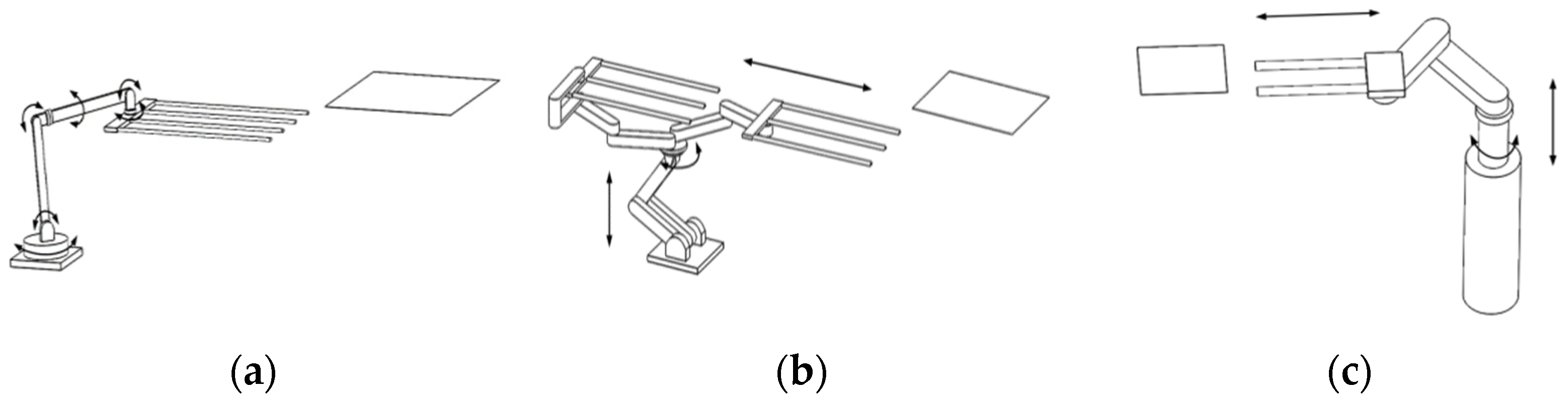
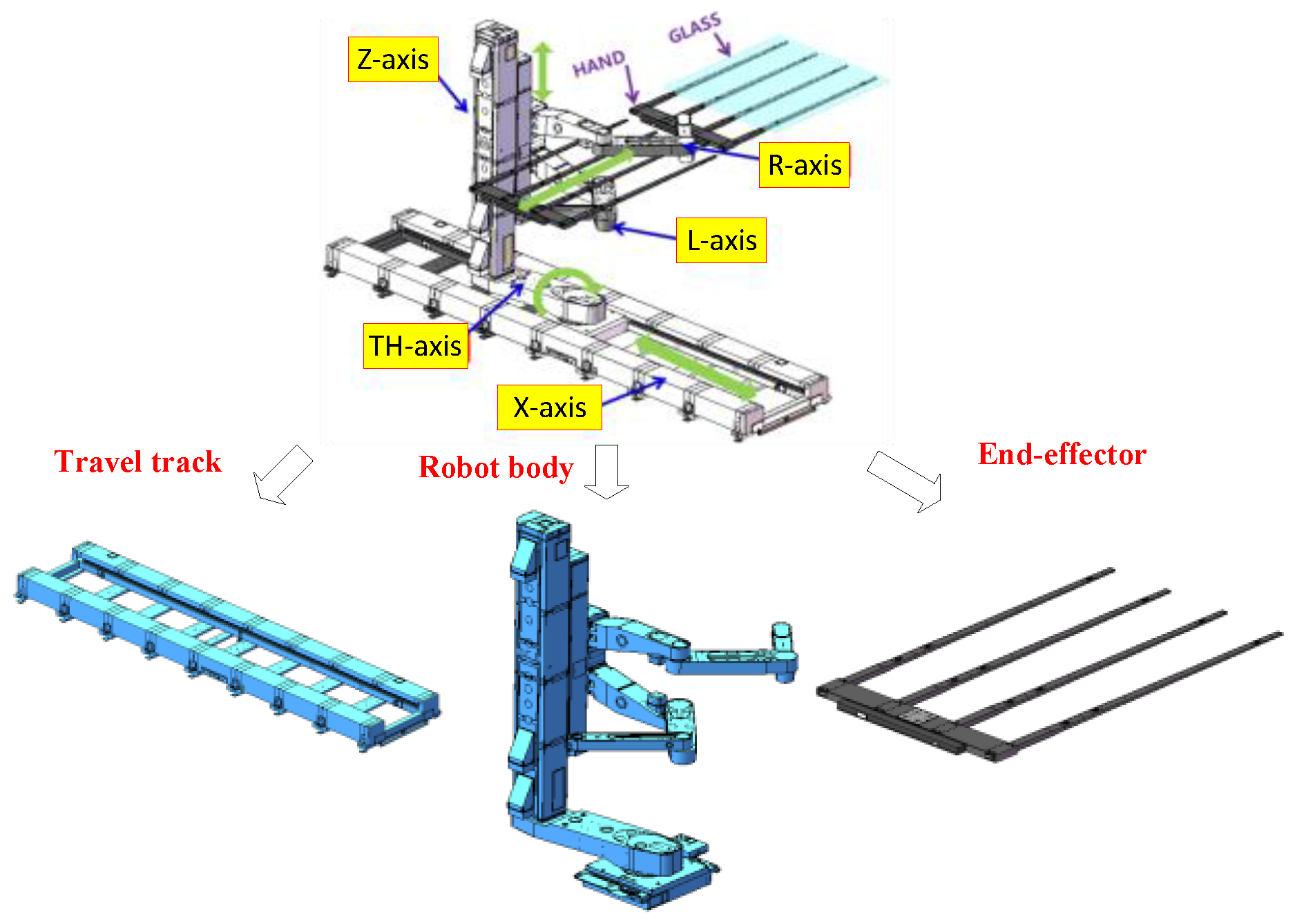
2. Structure Design
2.1. Design of the Travel Track
2.2. Structure of the Robot Body
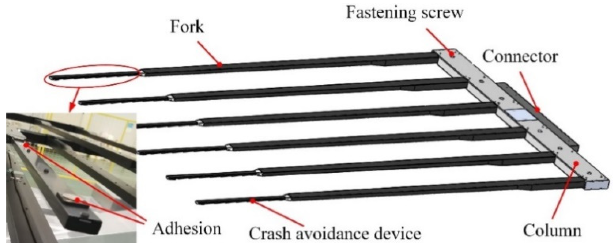
2.3. Design of the End-Effector
3. Structural Strength Verification
4. Robot Modelling and Control
4.1. Kinematic Analysis
4.2. Dynamic Analysis
4.3. Robot Control System
4.3.1. Hardware Level
4.3.2. Software Level
5. Experiment
5.1. Trace Experiment
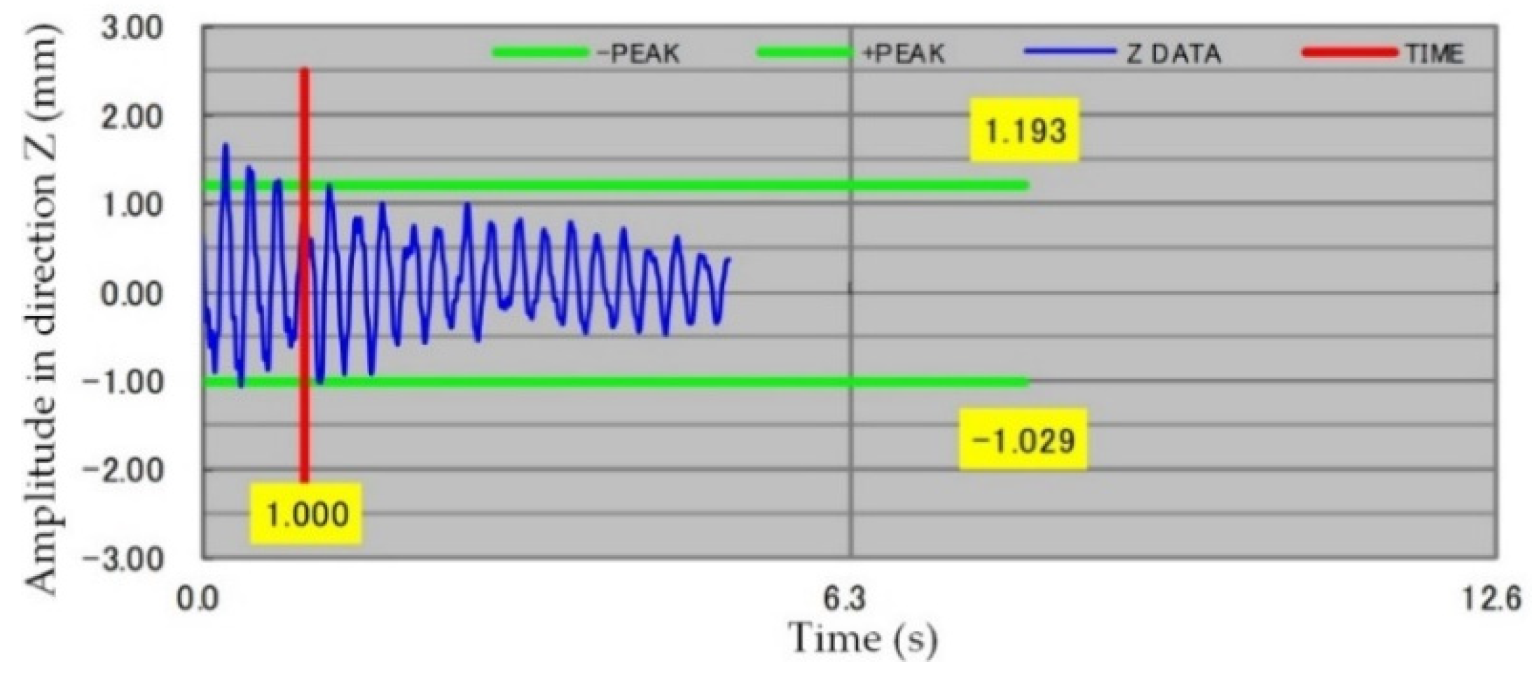
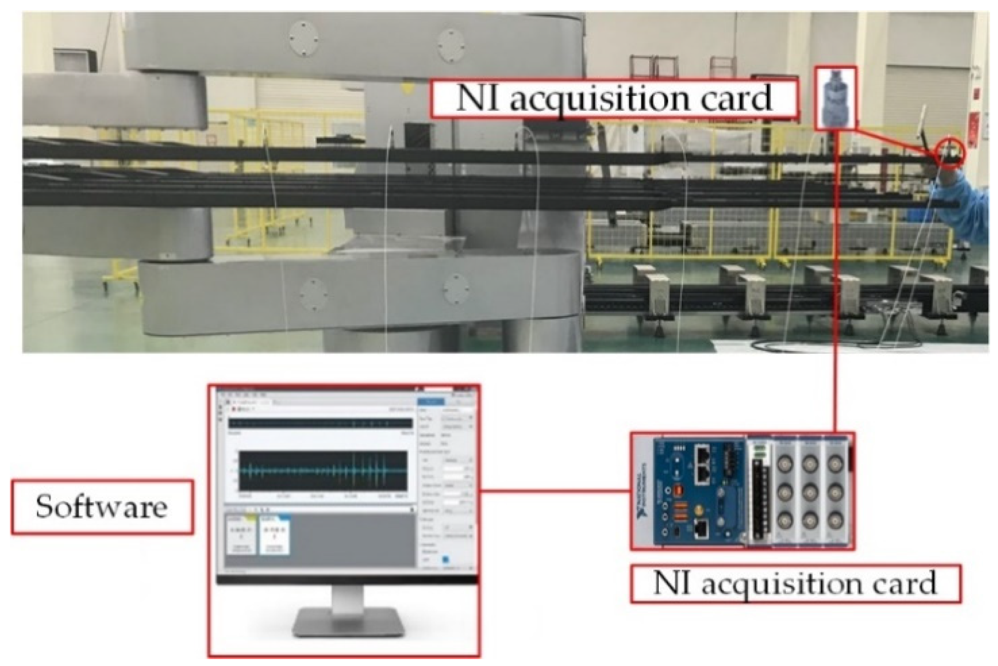
5.2. Fork Vibration Characteristic Experiment
5.3. Robot Functional Test
6. Conclusions
Author Contributions
Funding
Conflicts of Interest
References
- Park, D.I.; Park, C.H.; Yoo, Y. Vibration Simulation of Hybrid Type Substrate Handling Robot in the Vacuum Environment. In Proceedings of the 12th International Conference on Control, Automation and Systems (ICCAS), ICC, Jeju, Korea, 17–21 October 2012; pp. 2131–2134. [Google Scholar]
- Liu, C.; Chen, Y. Combined S-curve feedrate profiling and input shaping for glass substrate transfer robot vibration suppression. Ind. Robot 2018, 45, 549–560. [Google Scholar] [CrossRef]
- Park, C.H.; Park, D.I.; Do, H.M. Controller Design and Motion Simulation of Solar Cell Substrate Handling Robot in Vacuum Environment. In Proceedings of the 11th International Conference on Control, Automation and Systems (ICCAS), Gyeonggi-do, Korea, 26–29 October 2011; pp. 1017–1019. [Google Scholar]
- Tsuzuku, C. The trend of robot technology in semi-conductor and LCD industry. Ind. Robot 2001, 28, 406–413. [Google Scholar] [CrossRef]
- Seo, J.H.; Yim, H.J.; Hwang, J.C.; Choi, Y.W.; Kim, D.I. Dynamic load analysis and design methodology of LCD transfer robot. J. Mech. Sci. Technol. 2008, 22, 722–730. [Google Scholar] [CrossRef]
- Seo, J.-H.; Hwang, J.-C.; Choi, Y.-W.; Yim, H.-J. Analysis and design study of LCD transfer robot using dynamic simulation and experiment. J. Mech. Sci. Technol. 2009, 23, 1035–1039. [Google Scholar] [CrossRef]
- Zhang, Y. Vision Servo of Industrial Robot: A Review; American Institute of Physics: Huntington, WV, USA, 2018; Volume 1955. [Google Scholar]
- Jegal, M.; Kim, T.-H.; Hong, S.-H.; Yang, H.-S. Dynamic Modeling of Glass Substrate Transfer Robot Arm System by Using 5-Revolute Joints Manipulator Modeling Method. In Proceedings of the 12th International Conference on Control, Automation and Systems (ICCAS), ICC, Jeju, Korea, 17–21 October 2012; pp. 684–687. [Google Scholar]
- Feng, Y.; Qu, D.; Xu, F.; Wang, H.; Su, X. Analysis and Compensation For the Dynamic Error of The FPD Glass Substrates Transfer Robot. In Proceedings of the 2011 IEEE International Conference on Robotics and Automation, Shanghai, China, 9–13 May 2011. [Google Scholar]
- Chung, M.-J. Development of Transfer Robot using for Small Size Flat Panel Display Manufacturing Process. Appl. Mech. Mater. 2014, 541–542, 1146–1149. [Google Scholar] [CrossRef]
- Chu, H.K.; Mills, J.K.; Cleghorn, W.L. Automated dual-arm micromanipulation with path planning for micro-object handling. Robot. Auton. Syst. 2015, 74, 166–174. [Google Scholar] [CrossRef]
- Peplow, M. Glass beads help robots handle small-scale chemistry. Chem. Eng. News 2019, 97, 6. [Google Scholar]
- Zhang, Y.; Hou, R.; Wang, H.; Chen, X.; Yang, P. Numerical Simulation of Weak Parts of Main Components of Heavy-Duty Precision Brick Palletizing Robot. In Proceedings of the 4th International Conference on Environmental Science and Material Application (ESMA), Xi’an, China, 15–16 December 2019. [Google Scholar]
- Yu, X.; Baker, T.; Zhao, Y.; Tomizuka, M. Visual Servo for Fast Glass Handling by Industrial Robot with Large Sensor Latency and Low Sampling Rate. In Proceedings of the 20th World Congress of the International-Federation-of-Automatic-Control (IFAC), Toulouse, France, 9–14 July 2017; pp. 4594–4601. [Google Scholar]
- Paredis, C.J.J.; Brown, H.B.; Khosla, P.K. A rapidly deployable manipulator system. Robot. Auton. Syst. 1997, 21, 289–304. [Google Scholar] [CrossRef]
- Koivikko, A.; Drotlef, D.M.; Sitti, M.; Sariola, V. Magnetically switchable soft suction grippers. Extrem. Mech. Lett. 2021, 44, 101263. [Google Scholar] [CrossRef]
- Sucan, I.A.; Chitta, S. Motion Planning with Constraints Using Configuration Space Approximations. In Proceedings of the 25th IEEE/RSJ International Conference on Intelligent Robots and Systems (IROS), Algarve, Portugal, 7–12 October 2012; pp. 1904–1910. [Google Scholar]
- Qian, Y.; Zhang, A.; Chen, X. Yaskawa Robot Virtual Teaching Simulation Based on MotoSim EG. J. Wuxi Inst. Technol. 2017, 16, 47–49. [Google Scholar]
- Katafuchi, M. YASKAWA robot and robot application system at ‘93 International Industrial Robot Exhibition. Robot Tokyo 1994, 117–122. [Google Scholar]
- Kokusai Denk. Vacuum Processing Apparatus for Forming CVD Thin Film on LCD Glass Substrate-Has Robots Operated in Mutual Conjunction to Handle Substrates in and out of Substrate Chambers. Japan Patent JP11050256-A, 23 February 1999. [Google Scholar]
- Karaki, S.; Kondo, H.; Takemura, H.; Takemura, D. Substrate Handling System Comprises Substrate Handling Robot Provided with Hand, Second Substrate Transfer Device Provide with First Substrate Transfer Device and Substrate Transfer Robot Provided with Arm Lifting Mechanism. Japan Patent JP2020128289-A, 12 February 2019. [Google Scholar]
- Cong, M.; Xu, X.; Xu, P. Time-Jerk Synthetic Optimal Trajectory Planning of Robot Based on Fuzzy Genetic Algorithm. In Proceedings of the 2008 15th International Conference on Mechatronics and Machine Vision in Practice, Auckland, New Zealand, 2–4 December 2008; pp. 269–274. [Google Scholar]
- Jeong, H.E.; Lee, J.-K.; Kim, H.N.; Moon, S.H.; Suh, K.Y. A nontransferring dry adhesive with hierarchical polymer nanohairs. Proc. Natl. Acad. Sci. USA 2009, 106, 5639–5644. [Google Scholar] [CrossRef] [Green Version]
- Fremerey, M.; Maempel, J.; Witte, H.; Gorb, S.N. Towards an Adhesive Gripping Module for Handling Tasks and Small-Sized Climbing Robots; World Scientific Publ Co Pte Ltd.: Singapore, 2010; pp. 133–140. [Google Scholar]
- Sugiura, M.; Isobe, M. Studies on the mechanism of lipase reaction. III Adsorption of Chromobacterium lipase of hydrophobic glass beads. Chem. Pharm. Bull. 1976, 24, 72–78. [Google Scholar] [CrossRef] [Green Version]
- Tatsumi, Y.; Miyashita, K. Bipolar Electrostatic Chuck for Holding Silicon on Insulation Substrate in Plasma Processing Apparatus Has Electrodes Contacting Surface of Adsorbed Substrate. Japan Patent JP2006066857-A, 9 March 2006. [Google Scholar]
- Cho, P.-J.; Kim, D.-I.; Kim, H.-G. Real-time Static Deflection Compensation of an LCD Glass-Handling Robot. Trans. Korean Soc. Mech. Eng. A 2006, 30, 741–749. [Google Scholar]
- Trendafilova, I.; Van Brussel, H. Non-linear dynamics tools for the motion analysis and condition monitoring of robot joints. Mech. Syst. Signal Process. 2001, 15, 1141–1164. [Google Scholar] [CrossRef]
- Lee, D.H.; Kim, S.; Lee, C.; Cho, Y.H. Full Duplex Robot System for Transferring Flat Panel Display Glass. J. Korean Soc. Manuf. Technol. Eng. 2013, 22, 996–1002. [Google Scholar] [CrossRef]
- Li, S.; Tian, H.; Shao, J.; Liu, H.; Wang, D.; Zhang, W. Switchable Adhesion for Nonflat Surfaces Mimicking Geckos’ Adhesive Structures and Toe Muscles. ACS Appl. Mater. Interfaces 2020, 12, 39745–39755. [Google Scholar] [CrossRef] [PubMed]
- Autumn, K.; Liang, Y.A.; Hsieh, S.T.; Zesch, W.; Chan, W.P.; Kenny, T.W.; Fearing, R.; Full, R.J. Adhesive force of a single gecko foot-hair. Nature 2000, 405, 681–685. [Google Scholar] [CrossRef]
- Hu, H.; Tian, H.; Li, X.; Shao, J.; Ding, Y.; Liu, H.; An, N. Biomimetic Mushroom-Shaped Microfibers for Dry Adhesives by Electrically Induced Polymer Deformation. ACS Appl. Mater. Interfaces 2014, 6, 14167–14173. [Google Scholar] [CrossRef]
- Xu, T.; Fan, J.; Chen, Y.; Ng, X.; Ang, M.H.; Fang, Q.; Zhu, Y.; Zhao, J. Dynamic identification of the KUKA LBR iiwa robot with retrieval of physical parameters using global optimization. IEEE Access. 2020, 8, 108018–108031. [Google Scholar] [CrossRef]
- Fang, Q.; Li, G.; Xu, T.; Zhao, J.; Cai, H.; Zhu, Y. A Simplified Inverse Dynamics Modelling Method for a Novel Rehabilitation Exoskeleton with Parallel Joints and Its Application to Trajectory Tracking. Math. Probl. Eng. 2019, 2019, 4602035. [Google Scholar] [CrossRef]
- Li, G.; Fang, Q.; Xu, T.; Zhao, J.; Cai, H.; Zhu, Y. Inverse kinematic analysis and trajectory planning of a modular upper limb rehabilitation exoskeleton. Technol. Health Care Off. J. Eur. Soc. Eng. Med. 2019, 27, 123–132. [Google Scholar] [CrossRef] [PubMed] [Green Version]


| No. | 1 | 2 | 3 | 4 | 5 |
|---|---|---|---|---|---|
| Axis | X-axis | TH-axis | Z-axis | R-axis | L-axis |
| Description | travel track | Rotary axis | elevating axis, consisting of two sections of Z1-axis and Z2-axis when the stroke is larger | Upper arm movement axis | Lower arm movement axis |
| Characteristics | Value |
|---|---|
| Arm load | ≥65 kg |
| Maximum travel speed | ≥2.5 m/s |
| Repeatability | ±0.25 mm |
| Transverse vibration | ≤7 mm |
| Glass substrate size | ≥2940 mm × 3370 mm |
| Glass substrate thickness | Minimum 0.5 mm |
| Environmental cleanliness level | Better than Class10 (0.3 μm) |
| 1 | 587.52 | |
| 2 | 1235.88 | |
| 3 | 615.37 | |
| 4 | 400.88 | |
| 5 | 151.29 | |
| 6 | 68.48 | |
| 7 | 75.58 |
Publisher’s Note: MDPI stays neutral with regard to jurisdictional claims in published maps and institutional affiliations. |
© 2021 by the authors. Licensee MDPI, Basel, Switzerland. This article is an open access article distributed under the terms and conditions of the Creative Commons Attribution (CC BY) license (https://creativecommons.org/licenses/by/4.0/).
Share and Cite
Liu, Z.; Chen, Y.; Song, H.; Xing, Z.; Tian, H.; Shan, X. High-Speed Handling Robot with Bionic End-Effector for Large Glass Substrate in Clean Environment. Sensors 2022, 22, 149. https://doi.org/10.3390/s22010149
Liu Z, Chen Y, Song H, Xing Z, Tian H, Shan X. High-Speed Handling Robot with Bionic End-Effector for Large Glass Substrate in Clean Environment. Sensors. 2022; 22(1):149. https://doi.org/10.3390/s22010149
Chicago/Turabian StyleLiu, Zhengyong, Youdong Chen, Henan Song, Zhenming Xing, Hongmiao Tian, and Xiaobiao Shan. 2022. "High-Speed Handling Robot with Bionic End-Effector for Large Glass Substrate in Clean Environment" Sensors 22, no. 1: 149. https://doi.org/10.3390/s22010149