
Position Sensors for Industrial Applications Based on Electromagnetic Encoders


Abstract
:1. Introduction
2. Working Principle of Electromagnetic Encoders
3. Prototype Examples of Electromagnetic Encoders
3.1. Electromagnetic Encoders Based on Linear Strips
3.2. Electromagnetic Encoders Based on Dielectric Inclusions
3.3. Electromagnetic Encoders Based on Metallic Patches
4. Comparative Analysis and Discussion
5. Conclusions
Author Contributions
Funding
Conflicts of Interest
References
- Eitel, E. Basics of rotary encoders: Overview and new technologies. Mach. Des. Mag. 2014, 7, 1–9. [Google Scholar]
- McMillan, G.K.; Considine, D.M. Process-Instruments and Controls Handbook, 5th ed.; McGraw Hill: New York, NY, USA, 1999; pp. 5–26. [Google Scholar]
- Li, X.; Qi, J.; Zhang, Q.; Zhang, Y. Bias-tunable dual-mode ultraviolet photodetectors for photoelectric tachometer. Appl. Phys. Lett. 2014, 104, 411081–411084. [Google Scholar] [CrossRef]
- Petriu, E.M. Reconsidering natural binary encoding for absolute position measurement application. IEEE Trans. Instrum. Meas. 1989, 38, 1014–1016. [Google Scholar] [CrossRef]
- Jeong, K.; Park, J.; Yoon, J.S. High-precision encoder using moire fringe and neural network. In Proceedings of the SPIE in Optomechatronic Systems, Boston, MA, USA, 5 November 2000; pp. 1–7. [Google Scholar]
- Ueda, T.; Kohsaka, F.; Lino, T.; Kazami, K.; Nakayama, H. Optical absolute encoder using spatial filter. In Proceedings of the SPIE Photomechanics and Speckle Metrology, San Diego, CA, USA, 17 February 1987; pp. 217–221. [Google Scholar]
- Kikuchi, Y.; Nakamura, F.; Wakiwaka, H.; Yamada, H.; Yamamoto, Y. Consideration of magnetization and detection on magnetic rotary encoder using finite element method. IEEE Trans. Magn. 1997, 33, 2159–2162. [Google Scholar] [CrossRef]
- Jeong, S.H.; Rhyu, S.H.; Kwon, B.I.; Kim, B.T. Design of the rotary magnetic position sensor with the sinusoidally magnetized permanent magnet. IEEE Trans. Magn. 2007, 43, 1837–1840. [Google Scholar] [CrossRef]
- Nakano, K.; Takahashi, T.; Kawahito, S. A CMOS smart rotary encoder using magnetic sensor arrays. In Proceedings of the 2nd International Conference on Sensors (Sensors ’3), Toronto, ON, Canada, 22–24 October 2003; pp. 206–209. [Google Scholar]
- Lozanova, S.; Roumenin, C. Angular position device with 2D low-noise Hall microsensor. Sens. Actuators A Phys. 2010, 162, 167–171. [Google Scholar] [CrossRef]
- Lan, T.; Liu, Y.W.; Jin, M.H.; Fan, S.W.; Chen, Z.P.; Liu, H. Study of ultra-miniature giant magneto resistance sensor system based on 3D static magnetic analysis technique. Measurement 2009, 42, 1011–1016. [Google Scholar] [CrossRef]
- Hoang, H.V.; Jeon, J.W. An efficient approach to correct the signals and generate high-resolution quadrature pulses for magnetic encoders. IEEE Trans. Ind. Electron. 2011, 58, 3634–3646. [Google Scholar] [CrossRef]
- Zhang, Z.; Ni, F.; Dong, Y.; Jin, M.; Liu, H. A novel absolute angular position sensor based on electromagnetism. Sens. Actuators A 2013, 194, 196–203. [Google Scholar] [CrossRef]
- Zhang, Z.; Dong, Y.; Ni, F.; Jin, M.; Liu, H. A Method for Measurement of Absolute Angular Position and Application in a Novel Electromagnetic Encoder System. J. Sens. 2015, 2015, 503852. [Google Scholar] [CrossRef]
- Naqui, J.; Martín, F. Application of broadside-coupled split ring resonator (BC-SRR) loaded transmission lines to the design of rotary encoders for space applications. In Proceedings of the IEEE MTT-S International Microwave Symposium Digest (IMS’16), San Francisco, CA, USA, 22–27 May 2016; pp. 286–289. [Google Scholar]
- Herrojo, C.; Mata-Contreras, J.; Paredes, F.; Martín, F. Near-Field Chipless RFID Encoders with Sequential Bit Reading and High Data Capacity. In Proceedings of the IEEE MTT-S International Microwave Symposium Digest (IMS’17), Honolulu, HI, USA, 17–22 June 2017; pp. 1564–1567. [Google Scholar]
- Herrojo, C.; Mata-Contreras, J.; Paredes, F.; Martín, F. Microwave encoders for chipless RFID and angular velocity sensors based on S-shaped split ring resonators (S-SRRs). IEEE Sens. J. 2017, 17, 4805–4813. [Google Scholar] [CrossRef] [Green Version]
- Mata-Contreras, J.; Herrojo, C.; Martín, F. Application of split ring resonator (SRR) loaded transmission lines to the design of angular displacement and velocity sensors for space applications. IEEE Trans. Microw. Theory Tech. 2017, 65, 4450–4460. [Google Scholar] [CrossRef] [Green Version]
- Mata-Contreras, J.; Herrojo, C.; Martín, F. Electromagnetic rotary encoders based on split ring resonators (SRR) loaded microstrip lines. In Proceedings of the IEEE MTT-S International Microwave Symposium Digest (IMS’18), Philadelphia, PA, USA, 10–15 June 2018; pp. 43–46. [Google Scholar]
- Mata-Contreras, J.; Herrojo, C.; Martín, F. Detecting the rotation direction in contactless angular velocity sensors implemented with rotors loaded with multiple chains of split ring resonators (SRRs). IEEE Sens. J. 2018, 18, 7055–7065. [Google Scholar] [CrossRef]
- Herrojo, C.; Muela, F.; Mata-Contreras, J.; Paredes, F.; Martín, F. High-density microwave encoders for motion control and near-field chipless-RFID. IEEE Sens. J. 2019, 19, 3673–3682. [Google Scholar] [CrossRef]
- Herrojo, C.; Paredes, F.; Mata-Contreras, J.; Martín, F. All-dielectric electromagnetic encoders based on permittivity contrast for displacement/velocity sensors and chipless-RFID tags. In Proceedings of the IEEE MTT-S International Microwave Symposium Digest (IMS’19), Boston, MA, USA, 2–7 June 2019; pp. 295–392. [Google Scholar]
- Herrojo, C.; Paredes, F.; Martín, F. Double-stub loaded microstrip line reader for very high data density microwave encoders. IEEE Trans. Microw. Theory Tech. 2019, 67, 3527–3536. [Google Scholar] [CrossRef]
- Paredes, F.; Herrojo, C.; Martin, F. An approach for Synchronous Reading of Near-Field Chipless-RFID Tags. In Proceedings of the 10th IEEE International Conference RFID Technology and Applications (IEEE RFID-TA 2019), Pisa, Italy, 25–27 September 2019; pp. 192–196. [Google Scholar]
- Herrojo, C.; Paredes, F.; Martín, F. 3D-printed high data-density electromagnetic encoders based on permittivity contrast for motion control and chipless-RFID. IEEE Trans. Microw. Theory Tech. 2020, 68, 1839–1850. [Google Scholar] [CrossRef]
- Paredes, F.; Herrojo, C.; Escudé, R.; Ramon, E.; Martín, F. High Data Density Near-Field Chipless-RFID Tags with Synchronous Reading. IEEE J. RFID 2020, 4, 517–524. [Google Scholar] [CrossRef]
- Herrojo, C.; Paredes, F.; Martín, F. 3D-printed all-dielectric electromagnetic encoders with synchronous reading for measuring displacements and velocities. Sensors 2020, 20, 4837. [Google Scholar] [CrossRef]
- Paredes, F.; Herrojo, C.; Martín, F. Microwave Encoders with Synchronous Reading and Direction Detection for Motion Control Applications. In Proceedings of the IEEE MTT-S International Microwave Symposium Digest (IMS’20), Los Angeles, CA, USA, 18–27 June 2020; pp. 472–475. [Google Scholar]
- Paredes, F.; Herrojo, C.; Martín, F. Chipless-RFID Sensors for Motion Control Applications. In Proceedings of the URSI-GASS 2020, Rome, Italy, 29 August–5 September 2020. [Google Scholar]
- Herrojo, C.; Paredes, F.; Martín, F. 3D-Printed Microwave Encoders based on Embedded and Buried Dielectric Inclusions. In Proceedings of the URSI-GASS 2020, Rome, Italy, 29 August–5 September 2020. [Google Scholar]
- Paredes, F.; Herrojo, C.; Martín, F. Strategies for Synchronously Reading Microwave Encoders and Application to Sensors for Motion Control. In Proceedings of the 5th International Conference on Smart and Sustainable Technologies, Split, Croatia, 2–4 July 2020. [Google Scholar]
- Herrojo, C.; Paredes, F.; Martín, F. Synchronism and Direction Detection in High-Resolution/High-Density Electromagnetic Encoders. IEEE Sens. J. 2021, 21, 2873–2882. [Google Scholar] [CrossRef]
- Martín, F.; Herrojo, C.; Mata-Contreras, J.; Paredes, F. Time-Domain Signature Barcodes for Chipless-RFID and Sensing Applications, 1st ed.; Springer: Cham, Switzerland, 2020. [Google Scholar]
- De Bruijn, N.G. Acknowledgement of Priority to C. Flye Sainte-Marie on the Counting of Circular Arrangements of 2n Zeros and Ones that Show Each N-Letter Word Exactly Once; EUT Report; Technological University Eindhoven: Eindhoven, The Netherlands, 1975; pp. 1–16. [Google Scholar]
- Naqui, J.; Martín, F. Transmission Lines Loaded with Bisymmetric Resonators and their Application to Angular Displacement and Velocity Sensors. IEEE Trans. Microw. Theory Tech. 2013, 61, 4700–4713. [Google Scholar] [CrossRef]
- Naqui, J.; Martín, F. Angular displacement and velocity sensors based on electric-LC (ELC) loaded microstrip lines. IEEE Sens. J. 2014, 14, 939–940. [Google Scholar] [CrossRef] [Green Version]
- Naqui, J.; Coromina, J.; Karami-Horestani, A.; Fumeaux, C.; Martín, F. Angular displacement and velocity sensors based on coplanar waveguides (CPWs) loaded with S-shaped split ring resonator (S-SRR). Sensors 2015, 15, 9628–9650. [Google Scholar] [CrossRef] [Green Version]
- Naqui, J.; Martín, F. Microwave sensors based on symmetry properties of resonator-loaded transmission lines: A review. J. Sens. 2015, 2015, 741853. [Google Scholar] [CrossRef] [Green Version]
- Havlíček, J.; Herrojo, C.; Paredes, F.; Mata-Contreras, J.; Martín, F. Enhancing the per-unit-length data density in near-field chipless-RFID systems with sequential bit reading. IEEE Ant. Wirel. Prop. Lett. 2019, 18, 89–92. [Google Scholar] [CrossRef]
- Puentes, M.; Weiß, C.; Schüßler, M.; Jakoby, R. Sensor array based on split ring resonators for analysis of organic tissues. In Proceedings of the IEEE MTT-S International Microwave Symposium Digest (IMS’11), Baltimore, MD, USA, 17–22 June 2011; pp. 245–249. [Google Scholar]
- Ebrahimi, A.; Withayachumnankul, W.; Al-Sarawi, S.; Abbott, D. High-sensitivity metamaterial-inspired sensor for microfluidic dielectric characterization. IEEE Sens. J. 2014, 14, 1345–1351. [Google Scholar] [CrossRef] [Green Version]
- Boybay, M.S.; Ramahi, O.M. Material characterization using complementary split-ring resonators. IEEE Trans. Instrum. Meas. 2012, 61, 3039–3046. [Google Scholar] [CrossRef]
- Lee, C.S.; Yang, C.L. Complementary split-ring resonators for measuring dielectric constants and loss tangents. IEEE Microw. Wirel. Compon. Lett. 2014, 24, 563–565. [Google Scholar] [CrossRef]
- Yang, C.L.; Lee, C.S.; Chen, K.W.; Chen, K.Z. Noncontact measurement of complex permittivity and thickness by using planar resonators. IEEE Trans. Microw. Theory Tech. 2016, 64, 247–257. [Google Scholar] [CrossRef]
- Su, L.; Mata-Contreras, J.; Vélez, P.; Martín, F. Estimation of the complex permittivity of liquids by means of complementary split ring resonator (CSRR) loaded transmission lines. In Proceedings of the IEEE MTT-S International Microwave Workshop Series on Advanced Materials and Processes (IMWS-AMP 2017), Pavia, Italy, 20–22 September 2017. [Google Scholar]
- Su, L.; Mata-Contreras, J.; Vélez, P.; Fernández-Prieto, A.; Martín, F. Analytical method to estimate the complex permittivity of oil samples. Sensors 2018, 18, 984. [Google Scholar] [CrossRef] [Green Version]
- Falcone, F.; Lopetegi, T.; Baena, J.D.; Marqués, R.; Martín, F.; Sorolla, M. Effective negative-e stop-band microstrip lines based on complementary split ring resonators. IEEE Microw. Wirel. Compon. Lett. 2004, 14, 280–282. [Google Scholar] [CrossRef]
- Selga, J.; Sisó, G.; Gil, M.; Bonache, J.; Martín, F. Microwave circuit miniaturization with complementary spiral resonators (CSRs): Application to high-pass filters and dual-band components. Microw. Opt. Techol. Lett. 2009, 51, 2741–2745. [Google Scholar] [CrossRef]
- Herrojo, C.; Mata-Contreras, J.; Paredes, F.; Martín, F. High data density and capacity in chipless radiofrequency identification (chipless-RFID) tags based on double-chains of S-shaped split ring resonators (S-SRRs). EPJ Appl. Metamater. 2017, 4, 1–6. [Google Scholar] [CrossRef]
- Herrojo, C.; Mata-Contreras, J.; Paredes, F.; Martín, F. Near-field chipless RFID system with high data capacity for security and authentication applications. IEEE Trans. Microw. Theory Tech. 2017, 65, 5298–5308. [Google Scholar] [CrossRef] [Green Version]
- Herrojo, C.; Mata-Contreras, J.; Paredes, F.; Núñez, A.; Ramon, E.; Martín, F. Near-field chipless-RFID system with erasable/programmable 40-bit tags inkjet printed on paper substrates. IEEE Microw. Wirel. Compon. Lett. 2018, 28, 272–274. [Google Scholar] [CrossRef]
- Herrojo, C.; Mata-Contreras, J.; Paredes, F.; Núñez, A.; Ramón, E.; Martín, F. Near-field chipless-RFID tags with sequential bit reading implemented in plastic substrates. Int. J. Magn. Magn. Mater. 2018, 459, 322–327. [Google Scholar] [CrossRef]
- Herrojo, C.; Moras, M.; Paredes, F.; Núñez, A.; Ramón, E.; Mata-Contreras, J.; Martín, F. Very low-cost 80-bit chipless-RFID tags inkjet printed on ordinary paper. Technologies 2018, 6, 52. [Google Scholar] [CrossRef] [Green Version]
- Herrojo, C.; Paredes, F.; Mata-Contreras, J.; Ramon, E.; Núñez, A.; Martín, F. Time-domain signature barcodes: Near-field chipless-RFID systems with high data capacity. IEEE Microw. Mag. 2019, 20, 87–101. [Google Scholar] [CrossRef]
- Herrojo, C.; Paredes, F.; Mata-Contreras, J.; Martín, F. Chipless-RFID: A review and recent developments. Sensors 2019, 19, 3385. [Google Scholar] [CrossRef] [Green Version]
- Preradovic, S.; Karmakar, N.C. Chipless RFID: Bar code of the future. IEEE Microw. Mag. 2010, 11, 87–97. [Google Scholar] [CrossRef]
- Preradovic, S.; Karmakar, N.C. Multiresonator-Based Chipless RFID: Barcode of the Future, 1st ed.; Springer: Cham, Switzerland, 2011. [Google Scholar]
- Jalaly, I.; Robertson, I.D. RF barcodes using multiple frequency bands. In Proceedings of the IEEE MTT-S International Microwave Symposium Digest (IMS’5), Long Beach, CA, USA, 12–17 June 2005; pp. 139–142. [Google Scholar]
- Preradovic, S.; Balbin, I.; Karmakar, N.C.; Swiegers, G.F. Multiresonator-based chipless RFID system for low-cost item tracking. IEEE Trans. Microw. Theory Tech. 2009, 57, 1411–1419. [Google Scholar] [CrossRef] [Green Version]
- Preradovic, S.; Karmakar, N.C. Design of chipless RFID tag for operation on flexible laminates. IEEE Anten. Wirel. Propag. Lett. 2010, 9, 207–210. [Google Scholar] [CrossRef]
- McVay, J.; Hoorfar, A.; Engheta, N. Space-filling curve RFID tags. In Proceedings of the IEEE Radio Wireless Symposium, San Diego, CA, USA, 17–19 October 2006; pp. 199–202. [Google Scholar]
- Jalaly, I.; Robertson, D. Capacitively-tuned split microstrip resonators for RFID barcodes. In Proceedings of the European Microwave Conference, Paris, France, 3–7 October 2005; pp. 4–7. [Google Scholar]
- Jang, H.S.; Lim, W.G.; Oh, K.S.; Moon, S.M.; Yu, J.W. Design of low-cost chipless system using printable chipless tag with electromagnetic code. IEEE Microw. Wirel. Compon. Lett. 2010, 20, 640–642. [Google Scholar] [CrossRef]
- Vena, A.; Perret, E.; Tedjini, S. A fully printable chipless RFID tag with detuning correction technique. IEEE Microw. Wirel. Compon. Lett. 2012, 22, 209–211. [Google Scholar] [CrossRef]
- Vena, A.; Perret, E.; Tedjini, S. Design of compact and auto-compensated single-layer chipless RFID tag. IEEE Trans. Microw. Theory Tech. 2012, 60, 2913–2924. [Google Scholar] [CrossRef]
- Ahmadi Tameh, T.; Sawan, M.; Kashyap, R. Novel Analog Ratio-Metric Optical Rotary Encoder for Avionic Applications. IEEE Sens. J. 2016, 16, 6586–6595. [Google Scholar] [CrossRef]
- Nakamura, T.; Hayashi, K.; Yamane, H. A Motor-driven Ventricular Assist Device Controlled with an Optical Encoder System. Biomed. Mater. Eng. 1993, 3, 153–165. [Google Scholar] [CrossRef]
- Knobel, M.; Vázquez, M.; Kraus, L. Giant magnetoimpedance. Handb. Magn. Mater. 2003, 15, 497–563. [Google Scholar]
- Hauser, M.; Kraus, L.; Ripka, P. Giant magnetoimpedance sensors. IEEE Instrum. Meas. Mag. 2001, 4, 28–32. [Google Scholar] [CrossRef] [Green Version]
- Volchkov, S.O.; Lukshina, V.A.; Potapov, A.P.; Kurlyandskaya, G.V. A sensitive element based on the giant magnetoimpedance effect for detecting stray fields. Russ. J. Nondestruct. Test. 2009, 45, 595–603. [Google Scholar] [CrossRef]


| Encoder | Type | Resolution | Robustness 1 | Material 2 |
|---|---|---|---|---|
| Figure 3 | Rotary/Incremental | 0.3° | Poor | Cu/Microwave |
| Figure 5 | Linear/Absolute | 1.2 mm | Poor | Cu/Microwave |
| Figure 8 | Linear/Incremental | 5.2 mm | Good | Air/Microwave |
| Figure 11 | Linear/Incremental | 5.2 mm | Good | PLA/RS Pro MT-Copper |
| Figure 15 | Linear/Incremental | 3.4 mm | Good | Air/Microwave |
| Figure 17 | Linear/Incremental | 3.4 mm | Good | RS Pro MT-Copper/PLA |
| Figure 18 | Linear/Absolute | 3.4 mm | Good | Air/Microwave |
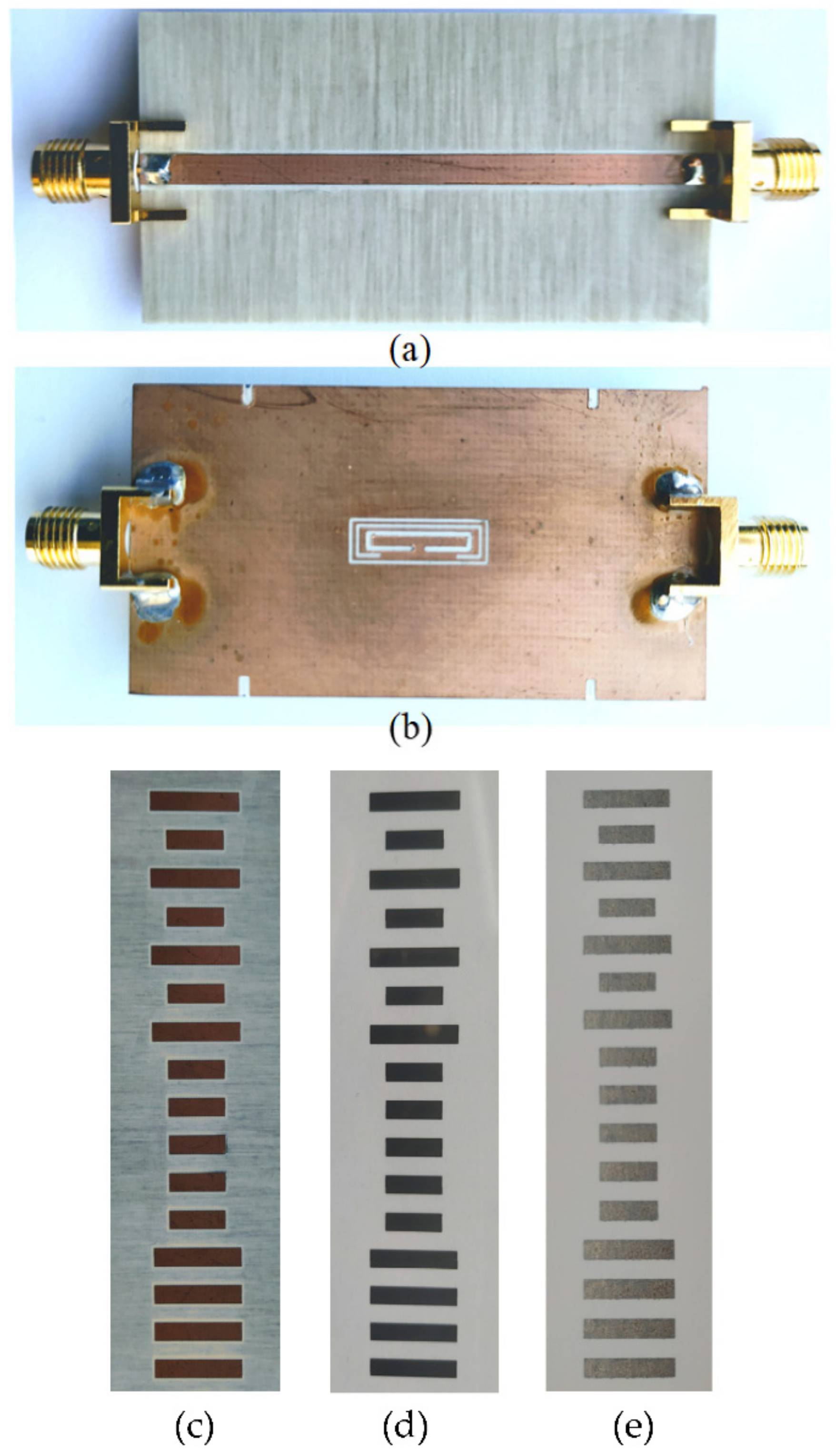
| Figure 21c | Linear/Absolute | 6.0 mm | Good | Cu/Microwave |
| Figure 21d | Linear/Absolute | 6.0 mm | Good | Conductive Ink/PEN |
| Figure 21e | Linear/Absolute | 6.0 mm | Good | Conductive Ink/Paper |
| Figure 26 | Linear/Absolute | 4.0 mm | Good | Cu/Microwave |
| Figure 28 | Linear/Absolute | 4.0 mm | Good | Conductive Ink/Polycarbonate |
| [17] | Rotary/Incremental | 2.25° | Poor | Cu/Microwave |
| [18] | Rotary/Incremental | 0.3° | Poor | Cu/Microwave |
| [19] | Rotary/Incremental | 0.6° | Poor | Cu/Microwave |
| [21] | Linear/Incremental | 0.6 mm | Poor | Cu/Microwave |
| [23] | Linear/Incremental | 0.6 mm | Poor | Cu/Microwave |
Publisher’s Note: MDPI stays neutral with regard to jurisdictional claims in published maps and institutional affiliations. |
© 2021 by the authors. Licensee MDPI, Basel, Switzerland. This article is an open access article distributed under the terms and conditions of the Creative Commons Attribution (CC BY) license (https://creativecommons.org/licenses/by/4.0/).
Share and Cite
Paredes, F.; Herrojo, C.; Martín, F. Position Sensors for Industrial Applications Based on Electromagnetic Encoders. Sensors 2021, 21, 2738. https://doi.org/10.3390/s21082738
Paredes F, Herrojo C, Martín F. Position Sensors for Industrial Applications Based on Electromagnetic Encoders. Sensors. 2021; 21(8):2738. https://doi.org/10.3390/s21082738
Chicago/Turabian StyleParedes, Ferran, Cristian Herrojo, and Ferran Martín. 2021. "Position Sensors for Industrial Applications Based on Electromagnetic Encoders" Sensors 21, no. 8: 2738. https://doi.org/10.3390/s21082738