Communication

Preliminary Investigation on Systems for the Preventive Diagnosis of Faults on Agricultural Operating Machines

Department of Agriculture and Forest Sciences, University of Tuscia, Via S. Camillo De Lellis, 01100 Viterbo, Italy
*
Author to whom correspondence should be addressed.
Sensors 2021, 21(4), 1547; https://doi.org/10.3390/s21041547
Submission received: 15 January 2021 / Revised: 12 February 2021 / Accepted: 18 February 2021 / Published: 23 February 2021

Abstract

:
This paper aims to investigate failures induced by vibrations on machines, focusing on agricultural ones. The research on literature has brought to light a considerable amount of data on the driven vehicles and not much on the operating machines, including the ones that we looked for. For this reason, it was decided to direct a survey with the people who work with agricultural machinery every day: operators, sub-contractors, and producers. They were asked about the most frequent breakage, particularly in relation to the rotary harrow, the topic of this work. The questionnaire results showed the types of failures the harrow is most vulnerable to, indicating the times of failure and reparation and the need to set up a potentially useful preventive maintenance supporting system on these machines. Part of the work was then focused on the proposition of a method to investigate bearing failures in the rotary harrow, considering that these have been analyzed in the technical literature and in the survey as the most at-risk components. The proposed method in this work serves as a beginning for the development of a future on board sent-shore-based maintenance system for continuous monitoring of the bearing.

1. Introduction

Rolling bearings, in the industrial application, are considered critical components [1]. In fact, a defect in a bearing, unless detected in time, can cause considerable industrial damage [2] as well as risks to human health. In particular, the phenomenon of vibrations can be potentially dangerous for human health, leading to strong negative effects [3,4]. Approximately more than half of all machine failures are due to bearing faults [5]. Bearing defects can occur during machine use, called distributed defects (surface roughness, waviness, and off-size rolling elements) [6], or during the manufacturing process, called local defects (cracks, pits, and spalls) [7]. The presence of defects leads to an increase in normal emission levels of noise and vibration in the bearings [3,8] and an increase in the level of Whole-Body Vibration (WBV) exposure for the driver of the vehicle [9]. Relevant exposure levels of whole-body can be dangerous for the driver [10] and, at the same time, are annoying during work activity [11]. In order to comprehend the ways of reducing the exposure to the WBV for the driver, many studies have been conducted [12], while other studies have been carried out in order to identify the effects of vibrations on machine components. On the basis of this characteristic, many researchers have studied the problem of rolling bearing defects in different ways. During the tests, some researchers ran bearings up to their failure in order to monitor changes of vibration response [13], some of the others intentionally introduced a defect in the bearing, under test, to evaluate the noise and vibration response, varying the size of the defect [14,15]. Many mechanical strains can occur with components of the machinery generated by many different types of vibration, for example, the torsional vibration of the crankshaft. These fatigues generate problems that are often detected after many work hours and cause crankshaft failure and undesirable engine noise [16]. Monitoring the roller bearing emissions, as an indication of wear, allows operators to manage preventive maintenance of the machine components. This avoids the unplanned maintenance, which takes place only at the breakdowns and which causes much higher repair costs than simply repairing the faulty component if it is detected early [17]. Different methods are used for the detection and diagnosis of bearing defects; they may be broadly classified as vibration and acoustic measurements, temperature measurements, and wear debris analysis [18,19,20]. A lot of studies have been carried out in the literature about the failure of driving machines, also in the agricultural fields [5,21,22]. An advanced system was developed in order to detect and control the frame vibration caused by a high-power engine and to prevent/reduces the potential damage to agricultural machinery [23,24]. It is based on intelligent sensor nodes at the measuring points of the two-stage vibration isolation system with the aim to assess the acceleration values and the frequency spectrums [24,25]. But few works have been conducted with respect to those with the problem of WBV exposure [26]. For this reason, this study takes into account the possible damages that can occur in the rolling bearings of agricultural operating machines, with a particular focus on the rotary harrow. Firstly, a questionnaire was given to workers, who day have to work with agricultural machinery every day, in order to collect information about the failures that usually affect harrows. Then, in order to evaluate the optimum level of operating conditions for the bearing in agricultural machines, we monitored the emitted vibrations through a tri-axial accelerometer fixed on the harrow structure. Beyond this optimum level, preventive maintenance is required. This paper shows the first raw values.

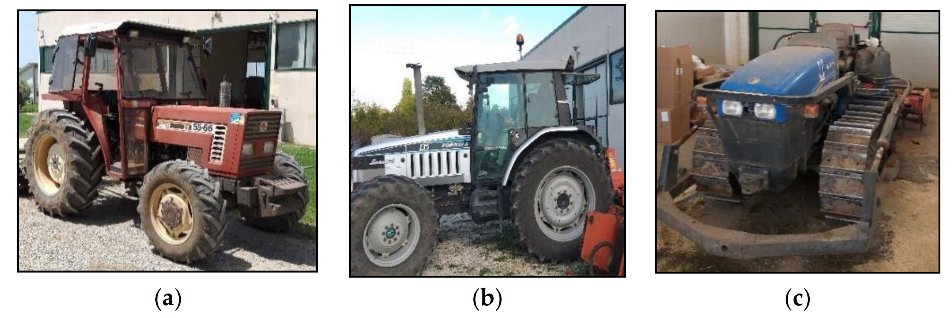
2. Materials and Methods

The research started with the formulation of a questionnaire aimed at agricultural operators and manufacturers of agricultural machinery. The purpose of the questionnaire was to determine the points of greatest risk of breakage in the harrow with rigid teeth and whether, effectively, a system of preventive maintenance can be useful (“activity one”). In parallel with the main subject of this study, an experiment was started at the experimental farm “N. Lupori” of the University of Tuscia (Italy), where it was possible to plan the data acquisition activities on rigid-tooth rotary harrows (“activity two”).

2.1. Investigation of Faults in Agricultural Machinery: The Rotary Harrow

A questionnaire was developed using Google forms, directed to operators, subcontractors, and manufacturers. The questions were:
  • Can you indicate below the role that best represents you at the present time?
  • What is the average frequency of failures in the power harrow?
  • What is the most common type of fault?
  • In the case of bearing failures, which are the most frequently affected?
  • In the event of a failure, how much do you think the average down-time (time from failure to repair) is?
  • In the most common cases of failure on a rotary harrow, how much do you think the repair costs will be? (Indicate an approximate cost or range of costs, from a minimum of... to a maximum of...).
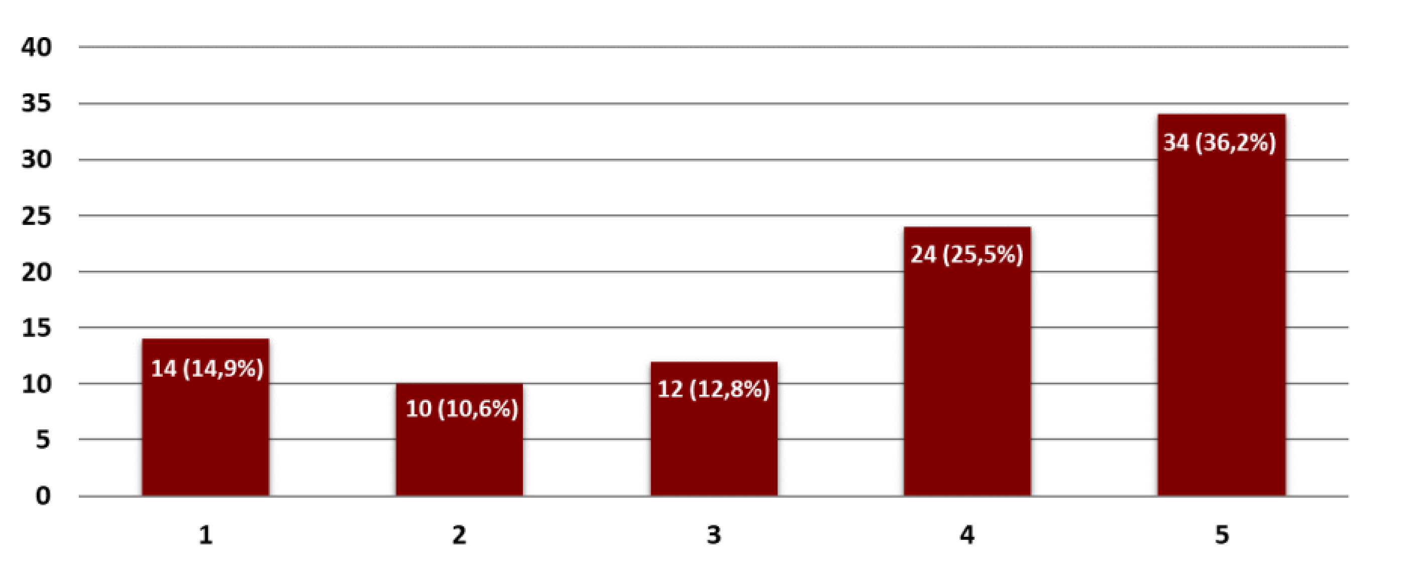
  • On a scale of 1 (not at all useful) to 5 (fully useful), how important would it be for you to have on board a system that warns the driver in advance of a possible breakdown of the machine (detecting the first signs of deterioration of particular elements well in advance before actual breakdowns occur)?

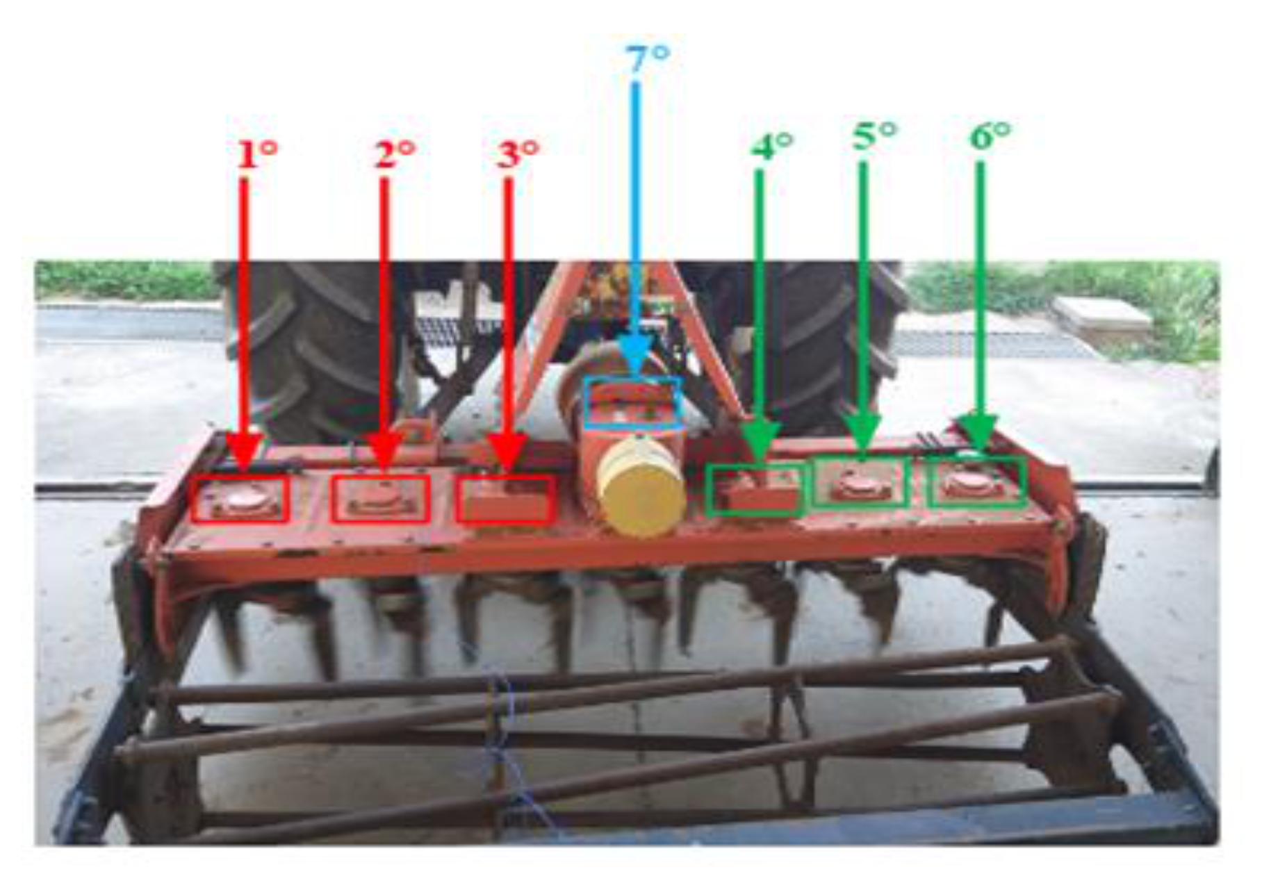
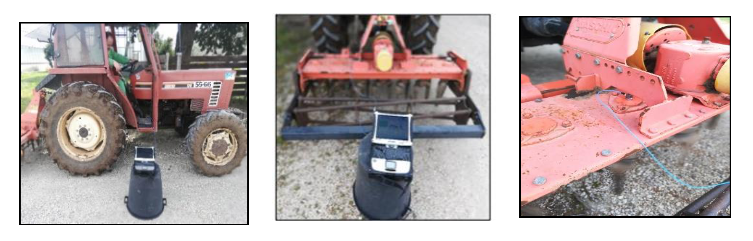
2.2. Description of Investigation Method for Bearing Failures in the Rotary Harrow

In order to characterize the mechanical structure of the harrow and highlight the influence of a vibration source, an experimental campaign was carried out in the same boundary conditions. The aim of this activity was to identify the influence of the signal source, represented by the tractor, on the vibration levels of each bearing. Due to the long time needed for signal acquisition and data processing for each test cycle, the measurements were repeated for several days. The experimental samples were acquired on three different tractors, Fiat 55l, New Holland TLK75FA 2005, and Lamborghini 135, as shown in Figure 1.
The measurements were obtained on two-wheeled tractors, and one tracked. The technical characteristics of each vehicle are shown in Table 1.
The measurement of vibratory levels of the harrow bearings was defined with the aim of identifying a methodology that is as repeatable as possible. The harrow under investigation was characterized by the presence of six bearings, distributed in a symmetrical way with respect to the Power Take-Off (PTO) with three bearings per side. The numbering has been defined by observing from behind the machine, identifying nr. 1 as the first bearing on the left and in progression up to nr. 6, last on the right, as shown in Figure 2.
The seventh bearing waqs assigned to the element mounted above the PTO. The positioning of the instrument is shown in Figure 3.
Measurements were realized for each bearing from number 1 to number 6; then the last acquisition was performed on the seventh bearing while keeping the angular speed of PTO constant with the following values: 600 rpm, 1000 rpm, 1500 rpm, and 2000 rpm. The measurement was carried out in the following way:
  • Start-up of the instrument to measure the signal for the bearing being evaluated;
  • Interruption of the measurement by the “pause” command;
  • The shift of the accelerometer to the next bearing;
  • Restart the measurement.
The acquisition time for each bearing was 60 s, except for the Lamborghini 135 with 120 s of measurement time. The data acquisition started when the engine speed was constant in order to avoid recording the transient signal between engine idle and the constant speed defined at the specific level, as described above. Then, seven intervals of time were extracted from the total measurement recorded. Every interval corresponded to each harrow bearing, and each data was classified according to the numbers from 1 to 7. This measurement technique was the best to obtain, from a single acquisition, both an overall assessment of the phenomenon of all mechanical elements of the harrow and the specific characterization of each bearing. The measurements were repeated three times in sequence for each level at a constant speed, with a break of about 20 min between tests, in order to avoid the excessive overheating of the surface. The instrument employed in this experimental campaign was a triaxial 393 PCB (PCB Piezotronics Inc., Depew, NY, USA) accelerometer (0.1 mV/ms−2). This device was specially designed for vibration analysis in vehicle testing, instrumentation, and equipment monitoring. It was mounted on the rigid metallic cover of the bearing and, before the positioning, the surface was cleaned to ensure better adherence of the instrument. The accelerometer was connected to a Sound-book MK2 system (SINUS Messtechnik GmbH, Leipzig, Germany), and the data was processed with the Noise and Vibration Work software (Spectra S.r.l., Vimercate, Italy). Subsequent to the recording of measurements, the data was saved in the sound-book device and finally was stored on a hard disk for the analysis. The sampling frequency was set to 1250 Hz. Once the setup of the sound-book was ready, a preliminary recording with minimal engine rpm was done in order to establish the efficiency and stability of the entire system, especially the engine of the tractor. For each signal, there has been obtained a graph of the Time History (trend of the signal to the variance of the time) and the frequency spectrum (one-third-octave bands), both for the overall measurement for each of the single bearings. Moreover, the values were also reported in terms of the equivalent level Leq, both in time as well as in energy content at various frequencies. Ultimately, the analysis was executed as an overall evaluation of the measurement to evaluate the stability of the source signal and for each individual bearing to define the specific strain. For instance, some illustrative graphs are presented in “Results”. The study was structured for analysis of the signal trend over time (Time History) to assess the bearing of any anomalous components due to diverse constituents, such as the instability of the hydraulic system that supports the harrow, which has generated sudden impulsive components. The measures were seen according to the procedure described above on the tractors in different phases due to the availability of vehicles on the farm.

3. Results

3.1. Questionnaire Preliminary Investigation

Ninety-four percent of the interviewees answered the questionnaire. The results showed that the failures along the rotary harrow occur at least one time per year. The favorable setting for the failure was represented by the rolling bearings or the tooth, close to the knives near the gear case. When a failure occurred, the average time needed for the repair was around 2–3 days, and the cost was about 900 euros. Figure 4 indicates the level of agreement of the interviewees for the implementation of an on-board system for preventive maintenance on a rotary harrow: the y-axis shows the percentage of agreement between the interviewees, and the x-axis is the level of utility to be 1 (low interest) to 5 (high interest).

3.2. Experimental Investigation

The experimental activity, conducted on the power harrow below investigation, was based on the analysis of the amplitude values and the frequency spectrum of the vibratory signal with the aim of characterizing the strains of each rolling bearing. The standardized measurement methodology was set with different steps: each measurement was repeated three times for each rolling bearing; it was carried out at different engine rpm, and the data acquired was analyzed at once, after the measurements, in order to infer the accuracy and the rightness of the process. The graphs in the following Figure 5, Figure 6, Figure 7 and Figure 8 show the acquisition data of the experimental measurement, comparing the signal (Time History) and frequency spectrum for each tractor. The blue line indicates the signal, vibration from the Fiat 55l, the red line from New Holland TLK75FA 2005, and the green line of the Lamborghini 135 tractors.
Table 2 shows the maximum values for each bearing in terms of velocity (mm/s) and frequency (Hz) for each direction (x, y, and z). The data is compared for each angular speed of the engines, which was defined before the trial. These values are more representative of the typical daily tractor activity.

4. Discussion

With the intent of demonstrating the applicative usefulness of a preventive maintenance system applied to agricultural operating machines, a questionnaire was conducted, considering the rotary harrow as a reference machine. This questionnaire, aimed at agricultural workers and machine makers, first highlighted the most frequent types of breakage, then highlighted the need to have a fault detection system on board. Moreover, the investigation has shown that the greatest number of failures concern the rolling bearings inside the machine’s kinematic chain. The measurement method proposed to assess the level of damage through emitted vibration of rolling bearings seemed useful. Acceleration along three axes in the direction of each bearing mounted on the harrow was measured with three different vibration sources represented by the tractors, as reported above. The measurement technique was repeated for each configuration with constant rpm at different stages. The purpose of the experimental campaign was to compare the frequency spectrum and vibration levels of each bearing in order to evaluate the consequence of any abnormal components due to wear. Results showed a reduction of acceleration values at the increasing of rpm, especially for the rolling bearings settled on the right side of the rotary harrow under investigation. Furthermore, the data obtained showed a different level of bearing wear due to the characteristics of the mechanical transmission from the PTO to each sprocket wheel. For each bearing, the signal recorded with the bearing showed a higher r.m.s. (root mean square) value compared to previous measurements at 1000, 1500, and 2000 rpm constant engine levels. The graphs of the frequency spectrum described above highlight the characteristics of the mechanical solicitations during the tests. The x-axis reports the values in terms of the third-octave bands. The range, until 2 Hz, was defined by the signal components that can be generated by thermic errors. The temperature of the harrow surface, where the sensor was fixed, could increase after a few minutes. It is possible to observe that the range starting from 63 Hz was defined by the solicitations caused by the rotary movement of spheres inside bearings. Furthermore, the components due to the rotation of the crankshaft and oscillation of the engine mechanical components were between 8 Hz and 31.5 Hz. The Lamborghini 135 tractor was the most stable source with an almost constant signal, while the Fiat 55l model showed a fairly variable signal. In conclusion, the results demonstrate that the tractor represents a source of vibration which strongly influences the measured signal. The Lamborghini 135 tractor was the most stable source with an almost constant signal, while the Fiat model showed a fairly variable signal. This last fact did not allow for careful characterization of the vibration signal.

5. Conclusions

An experiment was conducted in order to read the reaction of the bearings to different types of vibration sources. The result indicated the effects of engine speed and the influence of the type of source, represented by different tractors. The data was significantly important for the mean range values of the left and the right accelerometer in the x, y, and z directions. The results highlight that the conditions of the tractor (mass and degree wear) influence the signal vibration: an older tractor engenders a more unstable signal compared to a more recent one. It is necessary to point out that, despite the many factors influencing signal stability, measurements have shown acceptable results and encourage further studies regarding these problems. Another experiment could certainly contribute to the creation of a fairly complete database with the intention of accurately determining the characteristics of the vibrations on the bearings. This experiment could be performed in two different ways. Particularly, the tests could be conducted using different tractor models and, at the same time, repeating the measurements on the same machinery described in this work, after a defined period, in order to evaluate the presence of damages on the bearings.

Author Contributions

Conceptualization, M.C. and G.C.; validation, M.C.; investigation, G.C., L.B., S.F. and F.P.; data curation, A.C., G.C. and L.B.; writing—original draft preparation, G.C. and A.C.; writing—review and editing, F.P. and M.C.; supervision, M.C.; project administration, M.C.; funding acquisition, M.C. and A.C. All authors have read and agreed to the published version of the manuscript.

Funding

This research was funded by MIUR (Ministry for education, University and Research) PRIN 2015 grant number 2015KTY5NW “Optimization of operating machinery through the mission profile analysis for a more efficient agriculture” and in the frame of the MIUR initiative “Department of excellence” (Law 232/2016).

Institutional Review Board Statement

Not applicable.

Informed Consent Statement

Not applicable.

Data Availability Statement

Publicly available datasets were analyzed in this study. This data can be found here: https://drive.google.com/drive/folders/1FKhNAsyfXMIac6_T--mleEEASyDOG6Lv?usp=sharing (accessed on 20 February 2021).

Conflicts of Interest

The authors declare no conflict of interest.

References

  1. Mishra, C.; Samantaray, A.K.; Chakraborty, G. Rolling Element Bearing Defect Diagnosis under Variable Speed Operation through Angle Synchronous Averaging of Wavelet De-Noised Estimate. Mech. Syst. Signal. Process. 2016, 72, 206–222. [Google Scholar] [CrossRef]
  2. Sakai, T. Review and Prospects for Current Studies on Very High Cycle Fatigue of Metallic Materials for Machine Structural Use. J. Solid Mech. Mater. Eng. 2009, 3, 425–439. [Google Scholar] [CrossRef] [Green Version]
  3. Alfaro Degan, G.; Coltrinari, G.; Lippiello, D.; Pinzari, M. A comparison between methods for assessment of whole-body vibration exposure: A case study in a limestone quarry. Int. J. Saf. Secur. Eng. 2018, 8, 90–97. [Google Scholar] [CrossRef] [Green Version]
  4. Alfaro Degan, G.; Coltrinari, G.; Lippiello, D.; Pinzari, M. Risk assessment of the whole-body vibration exposure for drivers of armored vehicles: A case study. Int. J. Saf. Secur. Eng. 2016, 6, 53–62. [Google Scholar] [CrossRef] [Green Version]
  5. Thorsen, O.V.; Dalva, M. Failure Identification and Analysis for High-Voltage Induction Motors in the Petrochemical Industry. IEEE Trans. Ind. Appl. 1999, 35, 810–818. [Google Scholar] [CrossRef]
  6. Meyer, L.D.; Ahlgren, F.F.; Weichbrodt, B. An Analytic Model for Ball Bearing Vibrations to Predict Vibration Response to Distributed Defects. J. Mech. Des. 1980, 102, 205. [Google Scholar] [CrossRef]
  7. Marcantonio, V.; Monarca, D.; Colantoni, A.; Cecchini, M. Ultrasonic Waves for Materials Evaluation in Fatigue, Thermal and Corrosion Damage: A Review. Mech. Syst. Signal. Process. 2019, 120, 32–42. [Google Scholar] [CrossRef]
  8. Washo, M.W. A Quick Method of Determining Root Causes and Corrective Actions of Failed Ball Bearings. Lubric. Eng. 1996, 52, 206–213. [Google Scholar]
  9. Alfaro Degan, G.; Coltrinari, G.; Lippiello, D.; Pinzari, M. Effects of ground conditions on whole-body vibration exposure on cars: A case study of drivers of armored vehicles. WIT Trans. Built Environ. 2017, 176, 431–438. [Google Scholar]
  10. Alfaro Degan, G.; Antonucci, A.; Coltrinari, G.; Lippiello, D. Safety-oriented multi-task approach to manage whole-body vibration exposure among quarry operators. WIT Trans. Built Environ. 2019, 189, 43–53. [Google Scholar]
  11. Papa, M. Analysis of Agricultural Machinery to Reduce the Vibration to the Operator Seat. In Proceedings of the XXIV AIMETA Conference 2019, Rome, Italy, 15–19 September 2019; Springer Nature: New York, NY, USA, 2020; pp. 322–335. [Google Scholar]
  12. Cutini, M.; Brambilla, M.; Bisaglia, C. Whole-body vibration in farming: Background document for creating a simplified procedure to determine agricultural tractor vibration comfort. Agriculture 2017, 7, 84. [Google Scholar] [CrossRef] [Green Version]
  13. Nishio, K.; Hoshiya, S.; Miyachi, T.; Matsuki, M. An Investigation of the Early Detection of Defects in Ball Bearings by the Vibration Monitoring. ASME Press: New York, NY, USA, 1979; pp. 1–12. [Google Scholar]
  14. Tandon, N. A Comparison of Some Vibration Parameters for the Condition Monitoring of Rolling Element Bearings. Measurement 1994, 12, 285–289. [Google Scholar] [CrossRef]
  15. Tandon, N.; Nakra, B.C. Comparison of Vibration and Acoustic Measurement Techniques for the Condition Monitoring of Rolling Element Bearings. Tribol. Int. 1992, 25, 205–212. [Google Scholar] [CrossRef]
  16. Sun, L.; Luo, F.; Shang, T.; Chen, H.; Moro, A. Research on torsional vibration reduction of crankshaft in off-road diesel engine by simulation and experiment. J. Vibroeng. 2018, 20, 345–357. [Google Scholar]
  17. Heng, A.; Zhang, S.; Tan, A.C.C.; Mathew, J. Rotating Machinery Prognostics: State of the Art, Challenges and Opportunities. Mech. Syst. Signal. Process. 2009, 23, 724–739. [Google Scholar] [CrossRef]
  18. Yang, Y.; Wang, H.; Cheng, J.; Zhang, K. A Fault Diagnosis Approach for Roller Bearing Based on VPMCD under Variable Speed Condition. Measurement 2013, 46, 2306–2312. [Google Scholar] [CrossRef]
  19. Cantwell, W.J.; Morton, J. The Significance of Damage and Defects and Their Detection in Composite Materials: A Review. J. Strain Anal. Eng. Des. 1992, 27, 29–42. [Google Scholar] [CrossRef]
  20. Tandon, N.; Choudhury, A. A Review of Vibration and Acoustic Measurement Methods for the Detection of Defects in Rolling Element Bearings. Tribol. Int. 1999, 32, 469–480. [Google Scholar] [CrossRef]
  21. Boubezoul, A.; Koita, A.; Daucher, D. Vehicle Trajectories Classification Using Support Vectors Machines for Failure Trajectory Prediction. In Proceedings of the 2009 International Conference on Advances in Computational Tools for Engineering Applications, Beirut, Lebanon, 15–17 September 2009; IEEE: New York, NY, USA, 2009; pp. 486–491. [Google Scholar]
  22. Farrar, C.R.; Doebling, S.W.; Nix, D.A. Vibration–Based Structural Damage Identification. Philos. Trans. R. Soc. Lond. Ser. A Math. Phys. Eng. Sci. 2001, 359, 131–149. [Google Scholar] [CrossRef]
  23. Zoltewicz, J.S.; Mondello, S.; Yang, B.; Newsom, K.J.; Kobeissy, F.; Yao, C.; Lu, X.-C.M.; Dave, J.R.; Shear, D.A.; Schmid, K.; et al. Biomarkers Track Damage after Graded Injury Severity in a Rat Model of Penetrating Brain Injury. J. Neurotrauma 2013, 30, 1161–1169. [Google Scholar] [CrossRef] [PubMed]
  24. Basseville, M.; Benveniste, A.; Gach-Devauchelle, B.; Goursat, M.; Bonnecase, D.; Dorey, P.; Prevosto, M.; Olagnon, M. In Situ Damage Monitoring in Vibration Mechanics: Diagnostics and Predictive Maintenance. Mech. Syst. Signal Process. 1993, 7, 401–423. [Google Scholar] [CrossRef]
  25. Jin, X.; Chen, K.; Ji, J.; Zhao, K.; Du, X.; Ma, H. Intelligent vibration detection and control system of agricultural machinery engine. Measurement 2019, 145, 503–510. [Google Scholar] [CrossRef]
  26. Zeng, X.; Kociolek, A.M.; Khan, M.I.; Milosavljevic, S.; Bath, B.; Trask, C. Whole body vibration exposure patterns in Canadian prairie farmers. Ergonomics 2017, 60, 1064–1073. [Google Scholar] [CrossRef] [PubMed]
Figure 1. Fiat 55l (a), Lamborghini 135 (b), and New Holland TLK75FA 2005 (c).
Sensors 21 01547 g001
Figure 2. Rotary harrow under investigation.
Sensors 21 01547 g002
Figure 3. Positioning of the instrument near the machine and accelerometer on the harrow.
Sensors 21 01547 g003
Figure 4. Level of interest for the implementation of an on board system for preventive maintenance on a rotary harrow taken out from the questionnaire.
Sensors 21 01547 g004
Figure 5. Comparison of time history for all tractors at 1000 rpm.
Sensors 21 01547 g005
Figure 6. Frequency spectrum for all tractors at 600 rpm—Fiat 55L.
Sensors 21 01547 g006
Figure 7. Frequency spectrum for bearing nr. 7 at 2000 rpm—Lamborghini 135.
Sensors 21 01547 g007
Figure 8. Overall time history at 600 rpm—Fiat 55l.
Sensors 21 01547 g008
Table 1. Technical characteristic of the tractors.
TractorMass (kg)Motor Torque (Nm)Engine Power (kW)
Fiat 55l2925176.041
New Holland TLK75FA 20054150322.063
Lamborghini 1356100597.1100
Table 2. Data obtained for the bearings of each vehicle at different engine rpm.
TractorEngine SpeedBearing
Fiat 55l600 rpm8.5511.5224.0915.9210.619.9513.02
Fiat 55l600 rpm16161616161616
Fiat 55l1000 rpm10.7823.4440.4810.2410.1712.7414.08
Fiat 55l1000 rpm251612.512.512.512.512.5
Fiat 55l1500 rpm3.383.623.552.492.832.892.04
Fiat 55l1500 rpm6.325253152506.3160
Fiat 55l2000 rpm9.75.865.403.313.573.884.43
Fiat 55l2000 rpm31.531.531.531.531.531.531.5
New Holland TLK75FA 2005600 rpm6.115.024.484.465.967.274.89
New Holland TLK75FA 2005600 rpm6.36.36.331.56.36.36.3
New Holland TLK75FA 20051000 rpm4.405.0353.1734.304.6874.8163.74
New Holland TLK75FA 20051000 rpm2.52.52.52.52.52.52.5
New Holland TLK75FA 20051500 rpm5.595.484.194.655.295.445.46
New Holland TLK75FA 20051500 rpm25256325252525
New Holland TLK75FA 20052000 rpm6.004.988.639.679.988.8510.12
New Holland TLK75FA 20052000 rpm31.531.531.531.531.531.531.5
Lamborghini 135600 rpm3.452.936.122.798.473.324.45
Lamborghini 135600 rpm12.512.58010012512.54
Lamborghini 1351000 rpm3.123.113.462.903.254.033.21
Lamborghini 1351000 rpm101008010012.512.5250
Lamborghini 1351500 rpm415.985.308.273.533.795.063.84
Lamborghini 1351500 rpm252525100125315250
Lamborghini 1352000 rpm5.686.585.874.205.345.105.81
Lamborghini 1352000 rpm101010101251010
Publisher’s Note: MDPI stays neutral with regard to jurisdictional claims in published maps and institutional affiliations.

