
Hollow Core Bragg Fiber-Based Sensor for Simultaneous Measurement of Curvature and Temperature


Abstract
:1. Introduction
2. Structure, Fabrication and Properties of HCBF
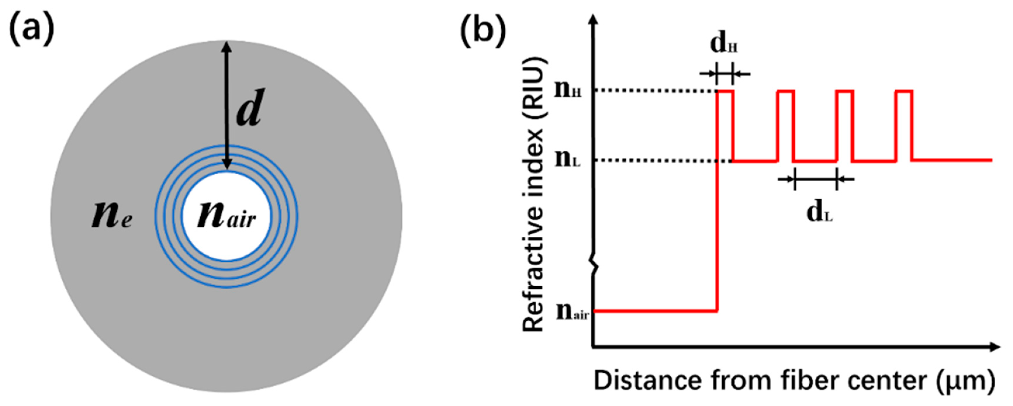
2.1. Structure
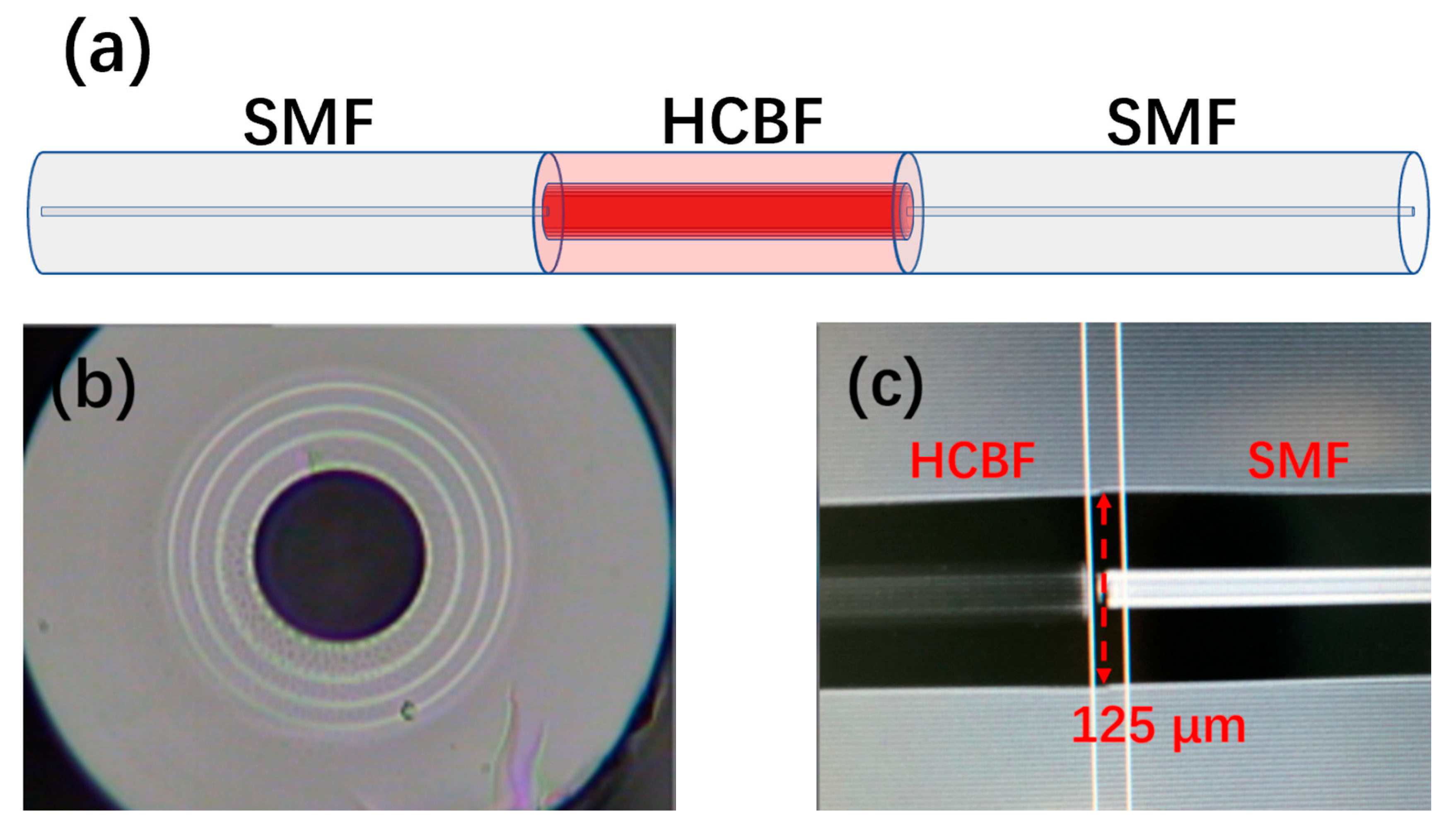
2.2. Fabrication
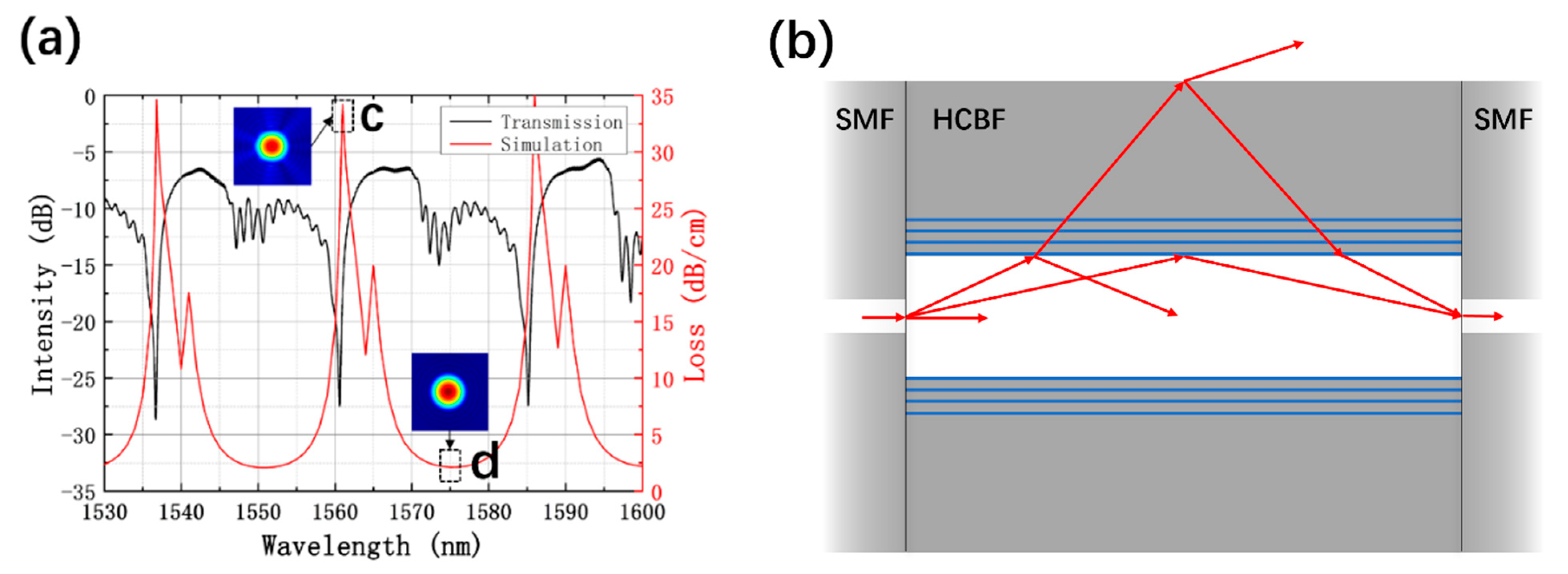
2.3. Property
3. Curvature and Temperature Sensing Experiment
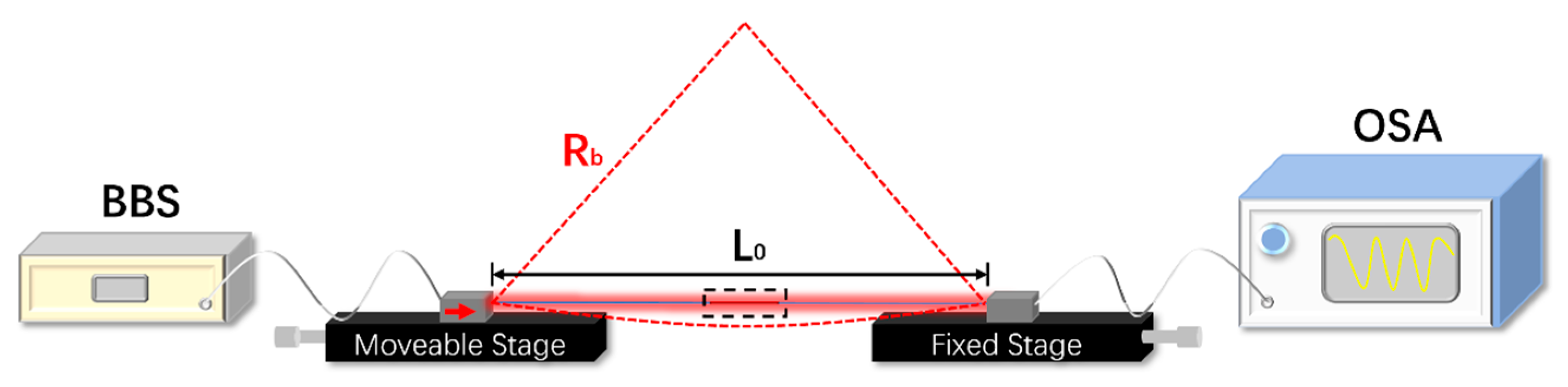
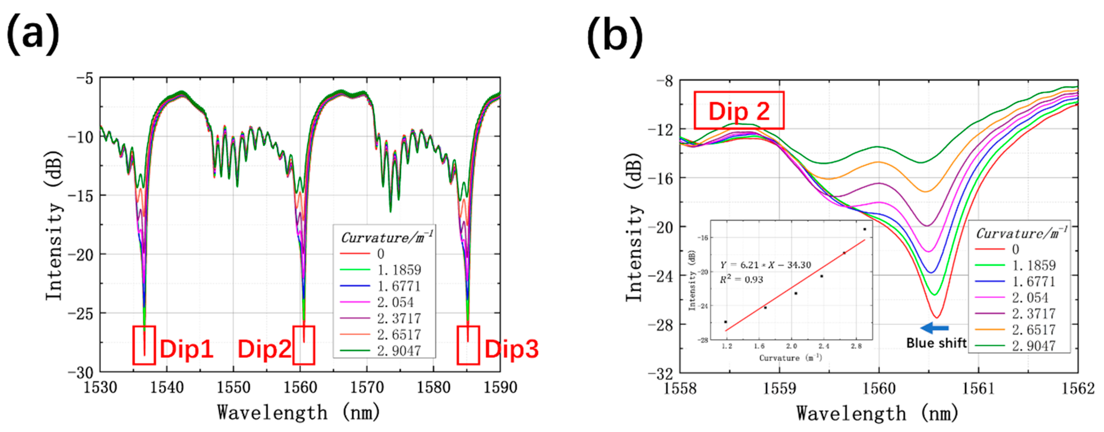
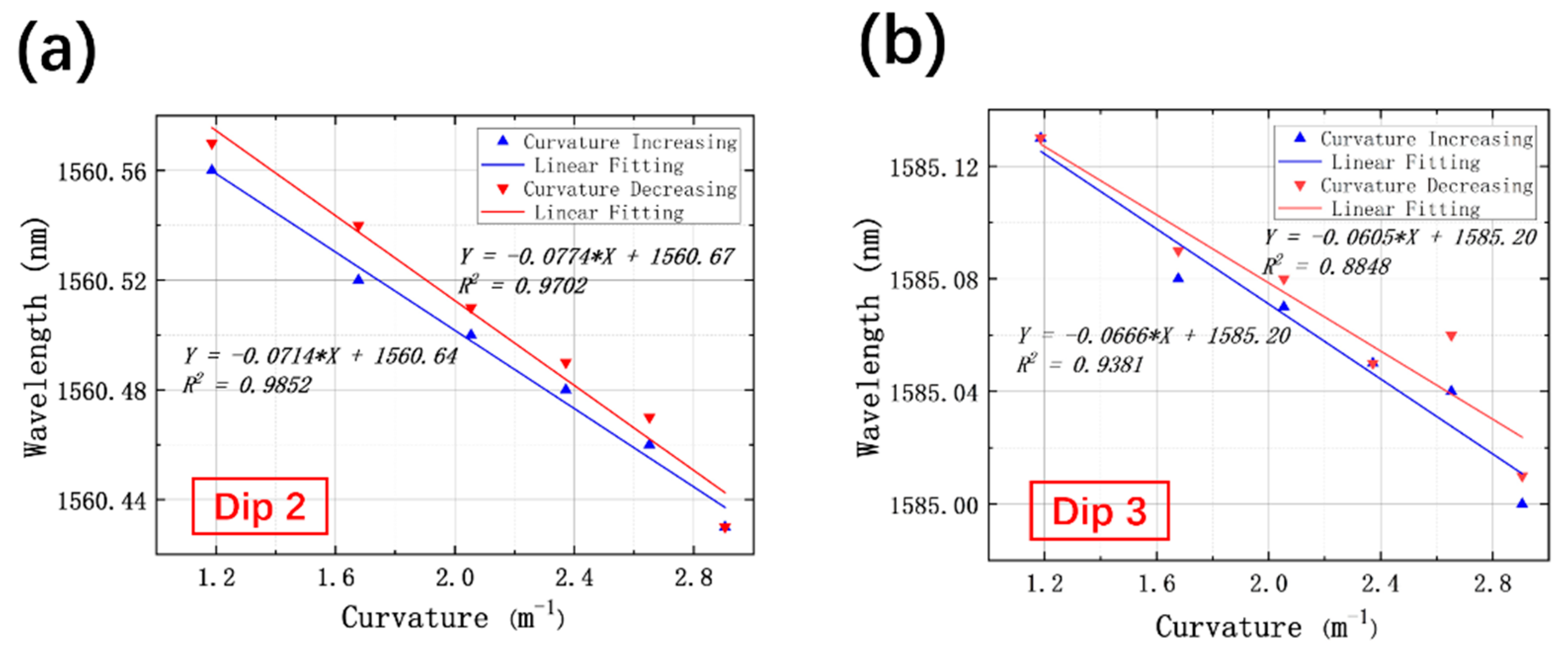
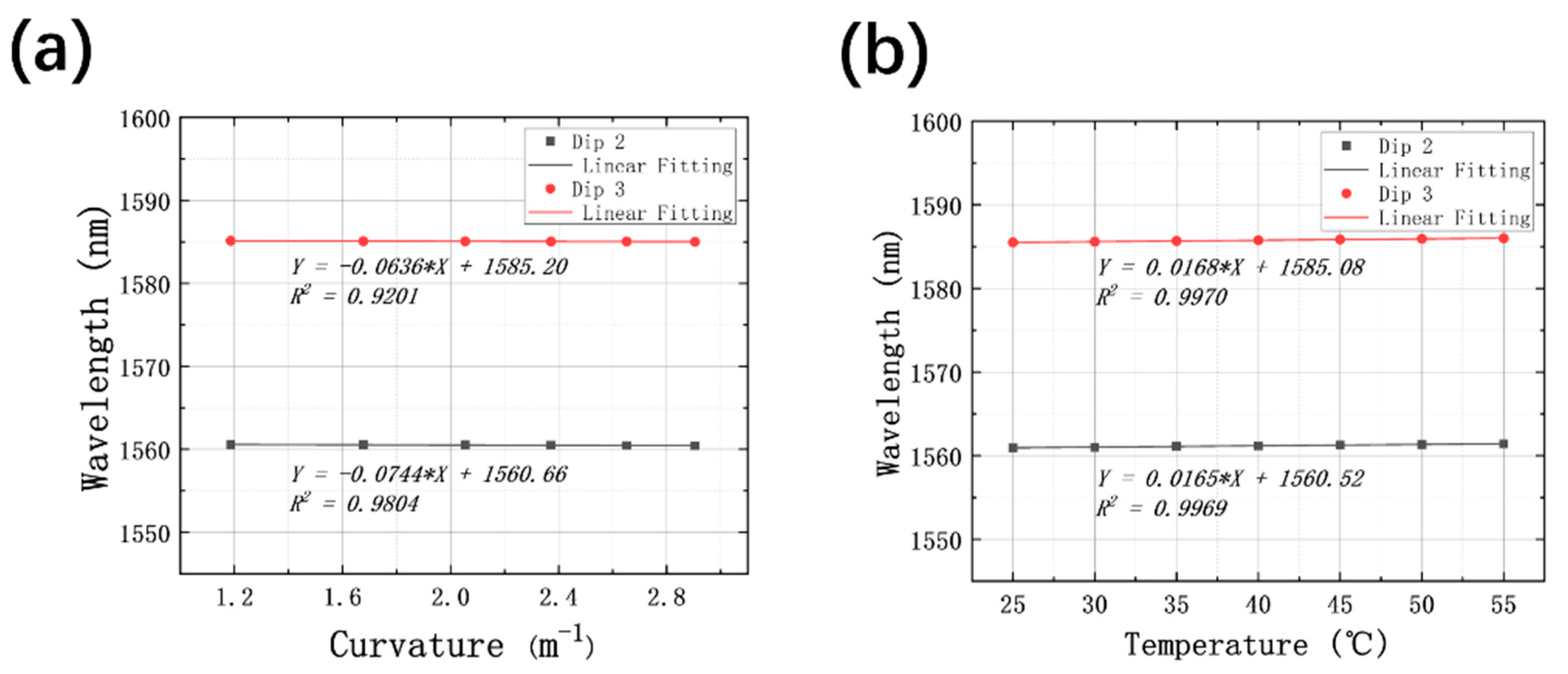
3.1. Curvature Sensing
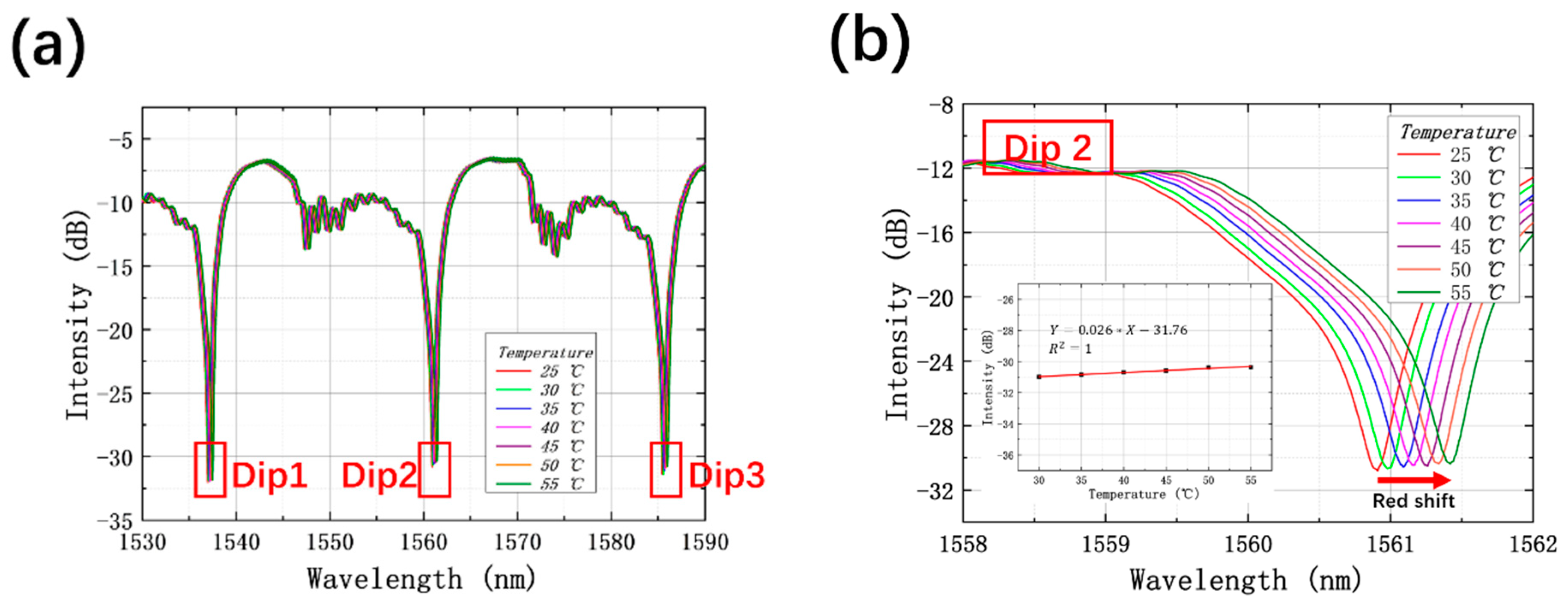
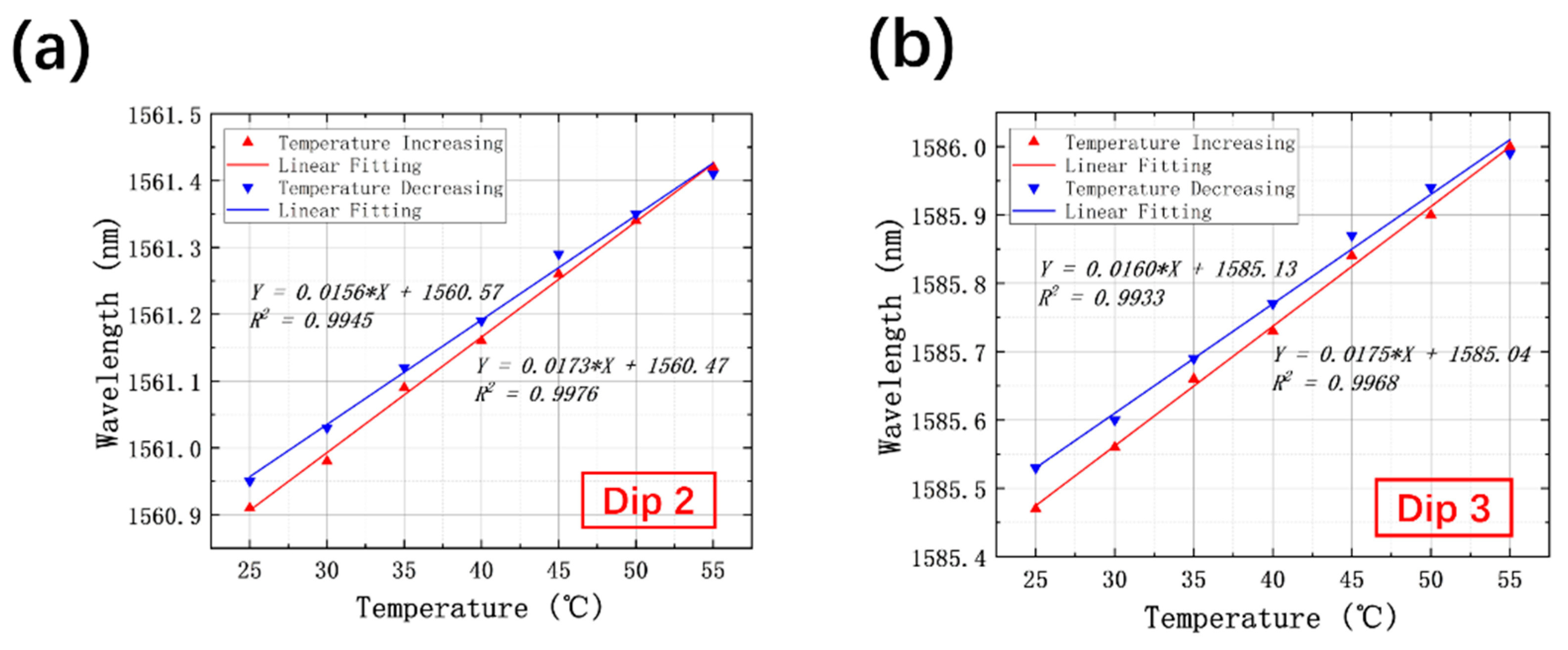
3.2. Temperature Sensing
4. Demodulation for Cross-Sensitivity of Curvature and Temperature
5. Conclusions
Author Contributions
Funding
Acknowledgments
Conflicts of Interest
References
- Zhang, Z.; Wang, X.; Wang, S.; Meng, D.; Liang, B. Shape detection and reconstruction of soft robotic arm based on fiber Bragg grating sensor array. In Proceedings of the 2018 IEEE International Conference on Robotics and Biomimetics (ROBIO), Kuala Lumpur, Malaysia, 12–15 December 2018. [Google Scholar]
- Bado, M.F.; Casas, J.R. A review of recent distributed optical fiber sensors applications for civil engineering structural health monitoring. Sensors 2021, 21, 1818. [Google Scholar] [CrossRef]
- Huston, D.R.; Bond, J.M. Shape sensing of inflatable aerospace structures with fiber optic curvature rosettes. In Proceedings of the Sensors and Smart Structures Technologies for Civil, Mechanical, and Aerospace Systems 2017, Portland, OR, USA, 25–29 March 2017. [Google Scholar]
- Stupar, D.Z.; Bajic, J.S.; Manojlovic, L.M.; Slankamenac, M.P.; Joza, A.V.; Zivanov, M.B. Wearable low-cost system for human joint movements monitoring based on fiber-optic curvature sensor. IEEE Sens. J. 2012, 12, 3424–3431. [Google Scholar] [CrossRef]
- Khan, F.; Denasi, A.; Barrera, D.; Madrigal, J.; Sales, S.; Misra, S. Multi-core optical fibers with Bragg gratings as shape sensor for flexible medical instruments. IEEE Sens. J. 2019, 19, 5878–5884. [Google Scholar] [CrossRef] [Green Version]
- Dong, S.; Dong, B.; Yu, C.; Guo, Y. High Sensitivity Optical Fiber Curvature Sensor Based on Cascaded Fiber Interferometer. J. Lightwave Technol. 2018, 36, 1125–1130. [Google Scholar] [CrossRef]
- Hu, X.; Peng, J.; Yang, L.; Li, J.; Li, H.; Dai, N. Design and fabrication of a heterostructured cladding solid-core photonic bandgap fiber for construction of Mach-Zehnder interferometer and high sensitive curvature sensor. Opt. Express 2018, 26, 7005–7012. [Google Scholar] [CrossRef] [PubMed]
- Arrizabalaga, O.; Sun, Q.; Beresna, M.; Lee, T.; Zubia, J.; Pascual, J.V.; De Ocáriz, I.S.; Schülzgen, A.; Antonio-Lopez, J.E.; Amezcua-Correa, R.; et al. High-performance vector bending and orientation distinguishing curvature sensor based on asymmetric coupled multi-core fibre. Sci. Rep. 2020, 10, 14058. [Google Scholar] [CrossRef] [PubMed]
- Zheng, D.; Madrigal, J.; Chen, H.; Barrera, D.; Sales, S. Multicore fiber-Bragg-grating-based directional curvature sensor interrogated by a broadband source with a sinusoidal spectrum. Opt. Lett. 2017, 42, 3710–3713. [Google Scholar] [CrossRef] [PubMed]
- Barrera, D.; Madrigal, J.; Sales, S. Long period gratings in multicore optical fibers for directional curvature sensor implementation. J. Lightwave Technol. 2018, 36, 1063–1068. [Google Scholar] [CrossRef]
- Zhao, Y.; Wang, C.; Yin, G.; Jiang, B.; Zhou, K.; Mou, C.; Liu, Y.; Zhang, L.; Wang, T. Simultaneous directional curvature and temperature sensor based on a tilted few-mode fiber Bragg grating. Appl. Opt. 2018, 57, 1671–1678. [Google Scholar] [CrossRef]
- Wu, Y.; Pei, L.; Jin, W.; Jiang, Y.; Yang, Y.; Shen, Y.; Jian, S. Highly sensitive curvature sensor based on asymmetrical twin core fiber and multimode fiber. Opt. Laser Technol. 2017, 92, 74–79. [Google Scholar] [CrossRef] [Green Version]
- Gong, Y.; Zhao, T.; Rao, Y.J.; Wu, Y. All-fiber curvature sensor based on multimode interference. IEEE Photonics Technol. Lett. 2011, 23, 679–681. [Google Scholar] [CrossRef]
- Yeh, P.; Yariv, A.; Marom, E. Theory of Bragg fiber. JOSA 1978, 68, 1196–1201. [Google Scholar] [CrossRef]
- Li, J.; Nallappan, K. Optimization of hollow-core photonic Bragg fibers towards practical sensing implementations. Opt. Mater. Express 2019, 9, 1640–1653. [Google Scholar] [CrossRef]
- Li, J.; Nallappan, K.; Guerboukha, H.; Skorobogatiy, M. 3D printed hollow core terahertz Bragg waveguides with defect layers for surface sensing applications. Opt. Express 2017, 25, 4126–4144. [Google Scholar] [CrossRef]
- Li, J.; Qu, H.; Skorobogatiy, M. Squeezed hollow-core photonic Bragg fiber for surface sensing applications. Opt. Express 2016, 24, 15687–15701. [Google Scholar] [CrossRef]
- Wang, S.; Wang, S.; Zhang, S.; Feng, M.; Wu, S.; Jin, R.-b.; Zhang, L.; Lu, P. An inline fiber curvature sensor based on anti-resonant reflecting guidance in silica tube. Opt. Laser Technol. 2019, 111, 407–410. [Google Scholar] [CrossRef]
- Yuan, W.; Li, L.; Wang, Y.; Lian, Z.; Chen, D.; Yu, C.; Lu, C. Temperature and curvature insensitive all-fiber sensor used for human breath monitoring. Opt. Express 2021, 29, 26375–26384. [Google Scholar] [CrossRef]
- Hu, D.J.J.; Alagappan, G.; Yeo, Y.-K.; Shum, P.P.; Wu, P. Broadband transmission in hollow-core Bragg fibers with geometrically distributed multilayered cladding. Opt. Express 2010, 18, 18671–18684. [Google Scholar] [CrossRef]
- Liu, Z.; Tse, M.-L.V.; Wu, C.; Chen, D.; Lu, C.; Tam, H.-Y. Intermodal coupling of supermodes in a twin-core photonic crystal fiber and its application as a pressure sensor. Opt. Express 2012, 20, 21749–21757. [Google Scholar] [CrossRef] [Green Version]
- Litchinitser, N.; Abeeluck, A.; Headley, C.; Eggleton, B. Antiresonant reflecting photonic crystal optical waveguides. Opt. Lett. 2002, 27, 1592–1594. [Google Scholar] [CrossRef]
- Zhao, Y.; Xia, F.; Chen, M.Q. Curvature sensor based on Mach–Zehnder interferometer with vase-shaped tapers. Sens. Actuators A Phys. 2017, 265, 275–279. [Google Scholar] [CrossRef]
- Wang, Y.; Richardson, D.; Brambilla, G.; Feng, X.; Petrovich, M.; Ding, M.; Song, Z. Intensity measurement bend sensors based on periodically tapered soft glass fibers. Opt. Lett. 2011, 36, 558–560. [Google Scholar] [CrossRef] [PubMed] [Green Version]


Publisher’s Note: MDPI stays neutral with regard to jurisdictional claims in published maps and institutional affiliations. |
© 2021 by the authors. Licensee MDPI, Basel, Switzerland. This article is an open access article distributed under the terms and conditions of the Creative Commons Attribution (CC BY) license (https://creativecommons.org/licenses/by/4.0/).
Share and Cite
Yang, Z.; Yuan, W.; Yu, C. Hollow Core Bragg Fiber-Based Sensor for Simultaneous Measurement of Curvature and Temperature. Sensors 2021, 21, 7956. https://doi.org/10.3390/s21237956
Yang Z, Yuan W, Yu C. Hollow Core Bragg Fiber-Based Sensor for Simultaneous Measurement of Curvature and Temperature. Sensors. 2021; 21(23):7956. https://doi.org/10.3390/s21237956
Chicago/Turabian StyleYang, Zongru, Weihao Yuan, and Changyuan Yu. 2021. "Hollow Core Bragg Fiber-Based Sensor for Simultaneous Measurement of Curvature and Temperature" Sensors 21, no. 23: 7956. https://doi.org/10.3390/s21237956