
Assessment and Feedback Control of Paving Quality of Earth-Rock Dam Based on OODA Loop


Abstract
:1. Introduction
2. Related Work
3. Research Framework
4. Methodologies
4.1. OODA Framework Coupled with CLA
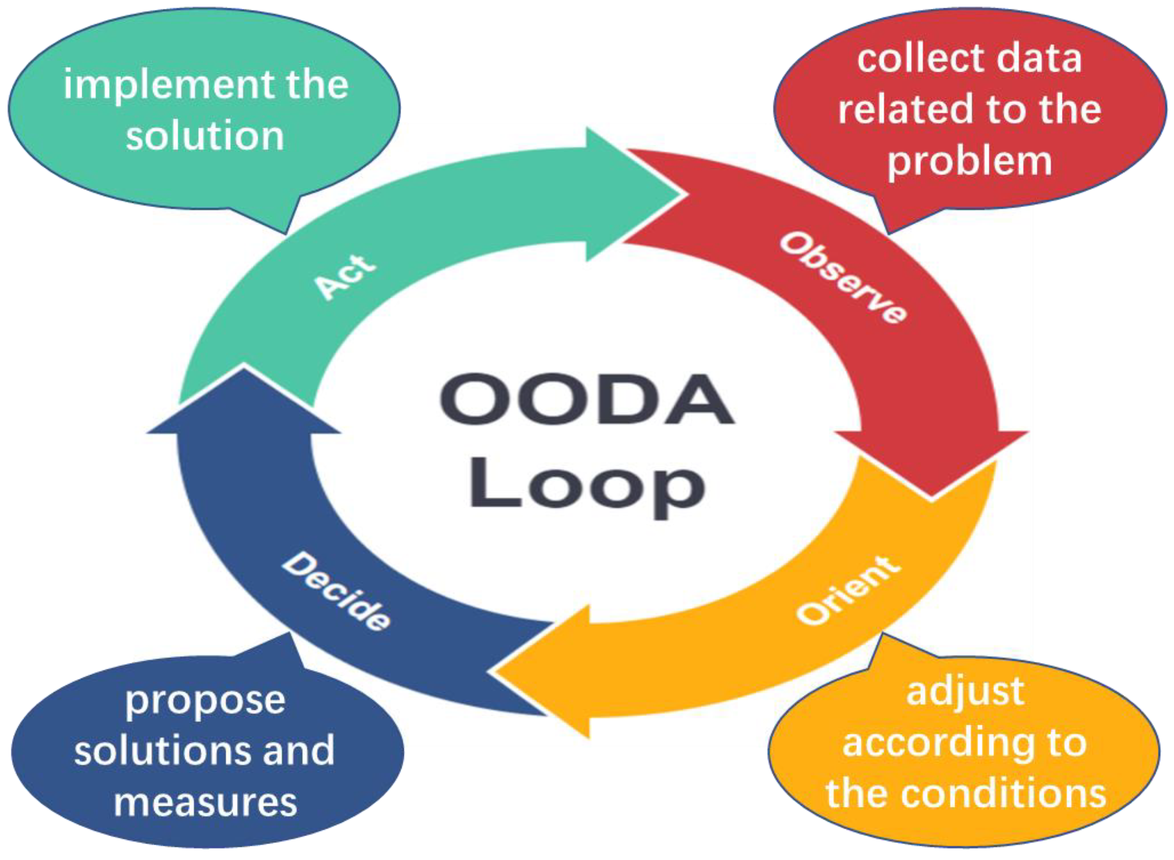
4.1.1. OODA Loop
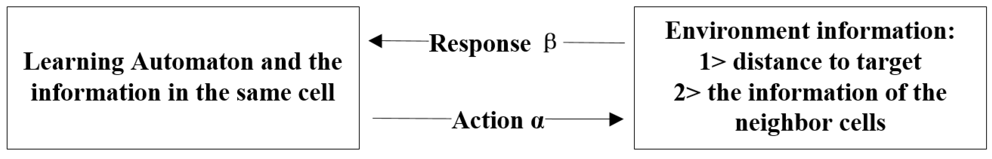
4.1.2. Cellular Learning Automaton
- The cellular coordinates will not change after the storehouse surface division stage is obtained.
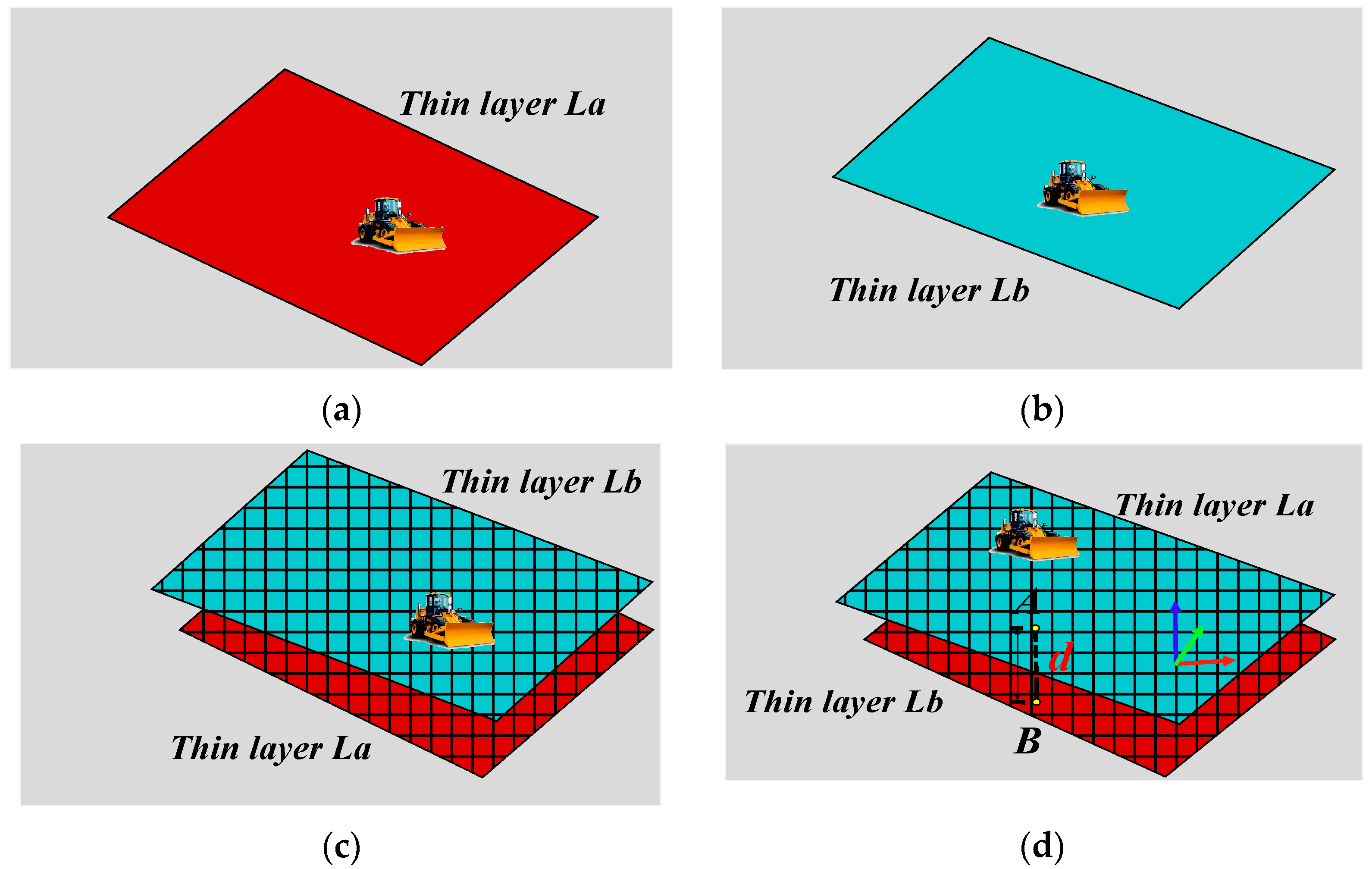
- The cellular activation value is determined by obtaining real-time monitoring data and the activation status information of the surrounding cells. The inactive state value is 0, when the bulldozer spatial position coordinates coincide with the cellular coordinates, the activation value is 1, when the activation value of the surrounding cell is 1, the activation state value of the cell becomes 1.1. When the spatial position coordinates of the dump truck coincide with the cellular coordinates , the activation value of the cell is changed to 2, and the activation values of the cellular coordinates and are changed to 2, thus determining that the activation values of the cells existing on the width of the mound are all updated to 2. In order to ensure that all the cells on the length of the mound are activated according to position, the activation value of cellular coordinates can be changed to 2.01, and so on. The other activation value of the cell is , then the activation value of the cells on both sides of the y direction is also changed to , the activation value of the cell at the position becomes .
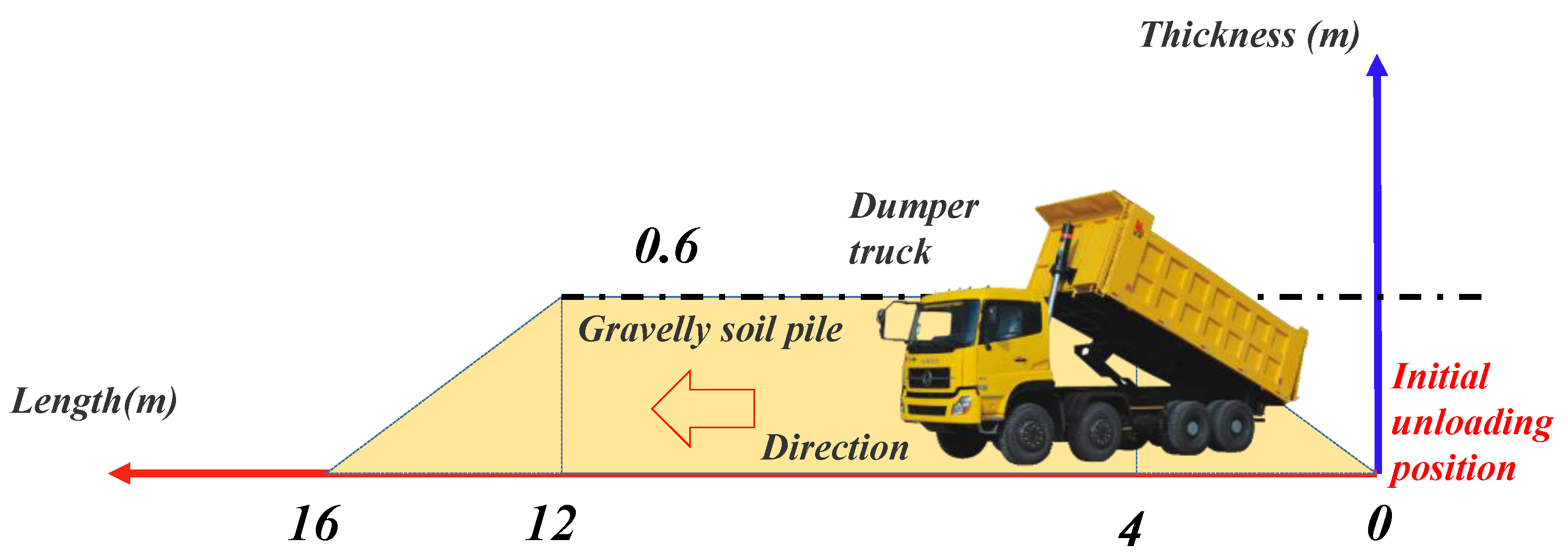
- The elevation can be obtained in different ways according to the activation value of the cell, when the activation value is 1 or 2, the elevation is equal to the elevation value in the real-time monitoring data of the bulldozer or dump truck. When the activation value is 1.1, because the cell is under the bulldozer, the elevation value is equal to the elevation value of cell with activation value of 1 at this time. When the activation value is , each cell corresponds to each position of the unloading pile. Elevation updates should be made according to Equation (3)where, is the updated elevation of this cell, m; is the pre renewing elevation of this cell, m; is the distance from the starting unloading position as shown in Figure 5, m.
- The thickness is generally updated according to the elevation value in the cell, and because the thickness update is the last step of the cell state update, the active state value is set to 0 after the thickness update. Thickness state transfer should satisfy the Equation (4).where, d is the thickness, m; is the updated elevation of the cell, m; is the elevation before updated of this cell, m.
4.1.3. OODA Framework Coupled with CLA
4.2. Dynamic Assessment and Control
4.2.1. Dynamic Assessment
4.2.2. Feedback Control
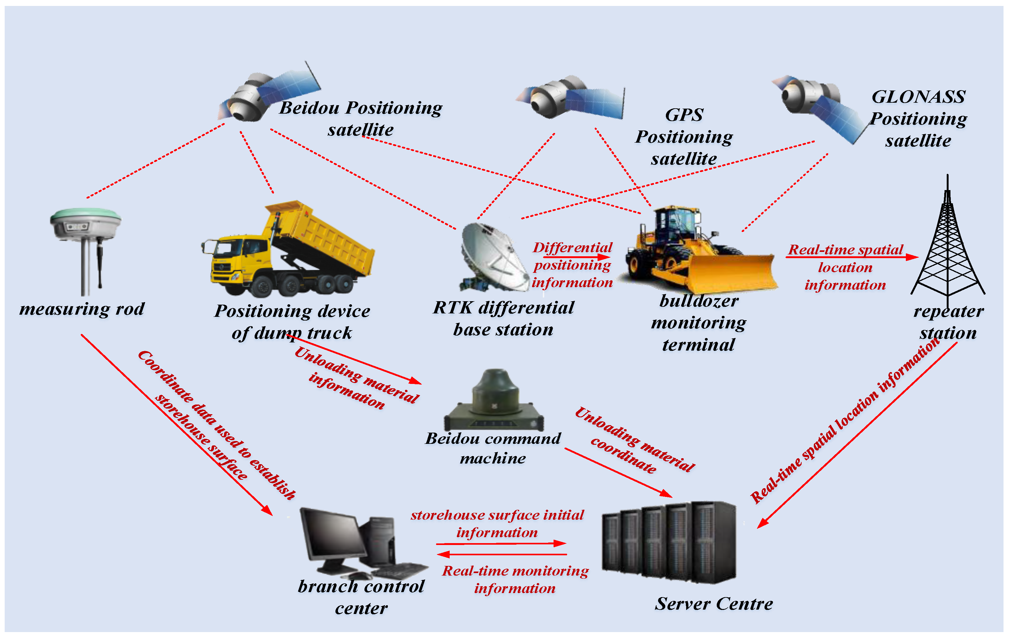
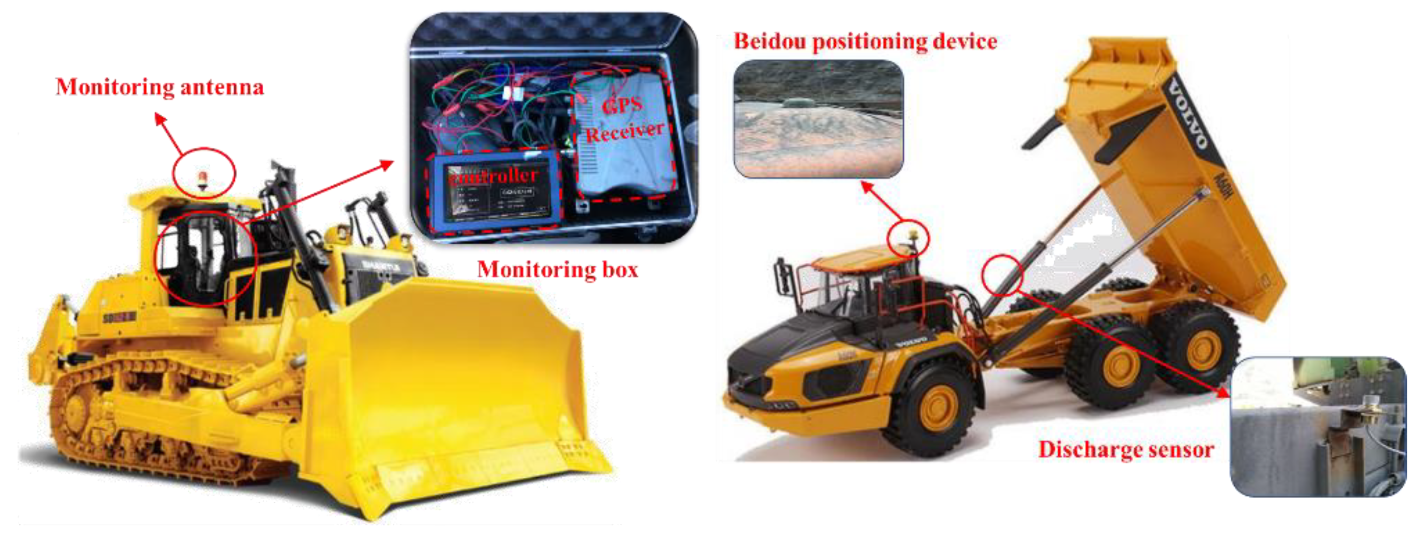
4.3. Parameter Acquisition Based on Real-Time Monitoring
5. Engineering Applications
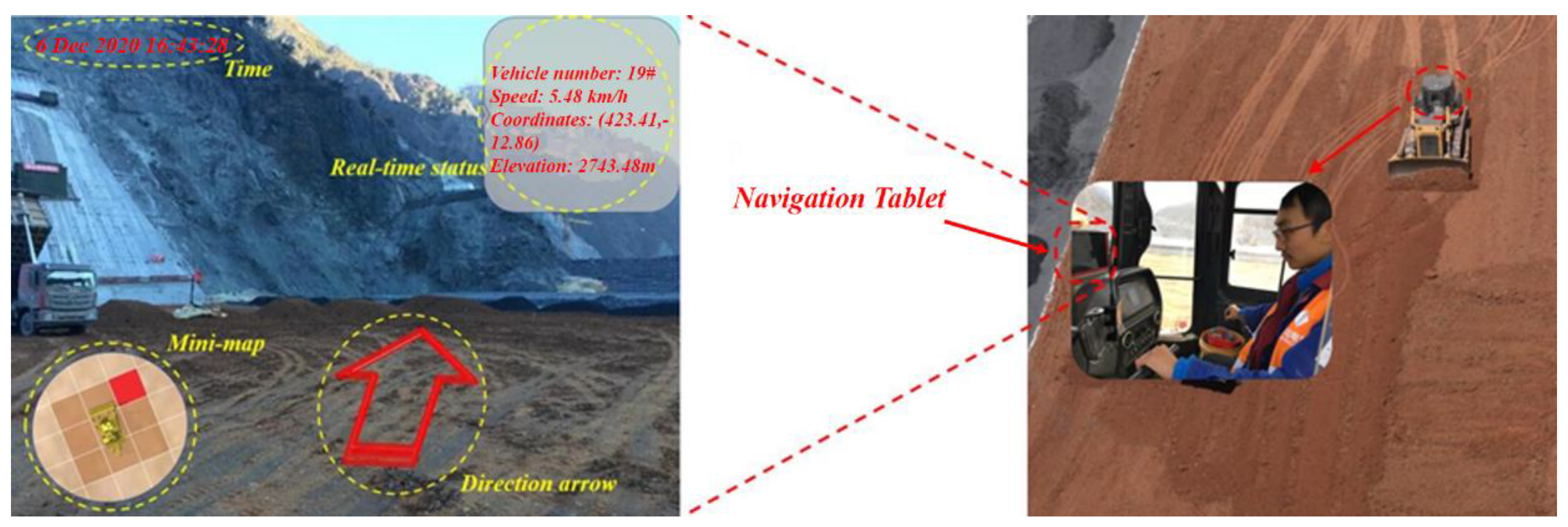
5.1. Real-Time Acquisition Process of Paving Operation Parameters
5.2. Dynamic Assessment
5.3. Feedback Control
| Algorithm1.Paving Quality Feedback Control |
| (1) Initialisation: |
| Input: target area coordinates, initial mounds, start_height, and target_height |
| (2) Main cycle |
| Parameters: Mound-the number of soil mounds in the dump area of the dump truck Endmain-the number of iterations Mounds.Add-the additive operator of the number of soil mounds Bulldozer.location-bulldozer coordinate variables; Get_location-position sensing operator Cell_Judge-LA judges behaviour according to the state of neighbouring cells PathPlanning-path planning operator Arrow-optimal path indicator variable Judge_quality-bulldozer paving quality evaluation operator |
| 1. Endmain = 0 |
| 2. While Endmain == 0 Do |
| 3. IF a new mound arises then |
| 4. mounds.Add(new mound) |
| 5. End |
| 6. Bulldozer.location = Get_location() |
| 7. Cell_Judge = get_arround(Bulldozer) |
| 8. Arrow = PathPlanning(mounds, Bulldozer, Cell_Judge) |
| 9. Show the Arrow on the Screen |
| 10. Update Bulldozer ‘s location and the cell that it passed just now |
| 11. Endmain = Judge_quality() |
| 12. End |
5.4. Discussion
6. Conclusions and Future Research
- The OODA framework coupled with the CLA is established to realise the dynamic assessment and control of the paving quality. The CLA improves the observe and orient modules in the OODA framework. The former converts the initial paving information into quality information through CAs and performs partition storage and partition updates. The latter interacts with the surrounding environment via LAs, such that the cells can be processed more specifically according to the mechanical operation.
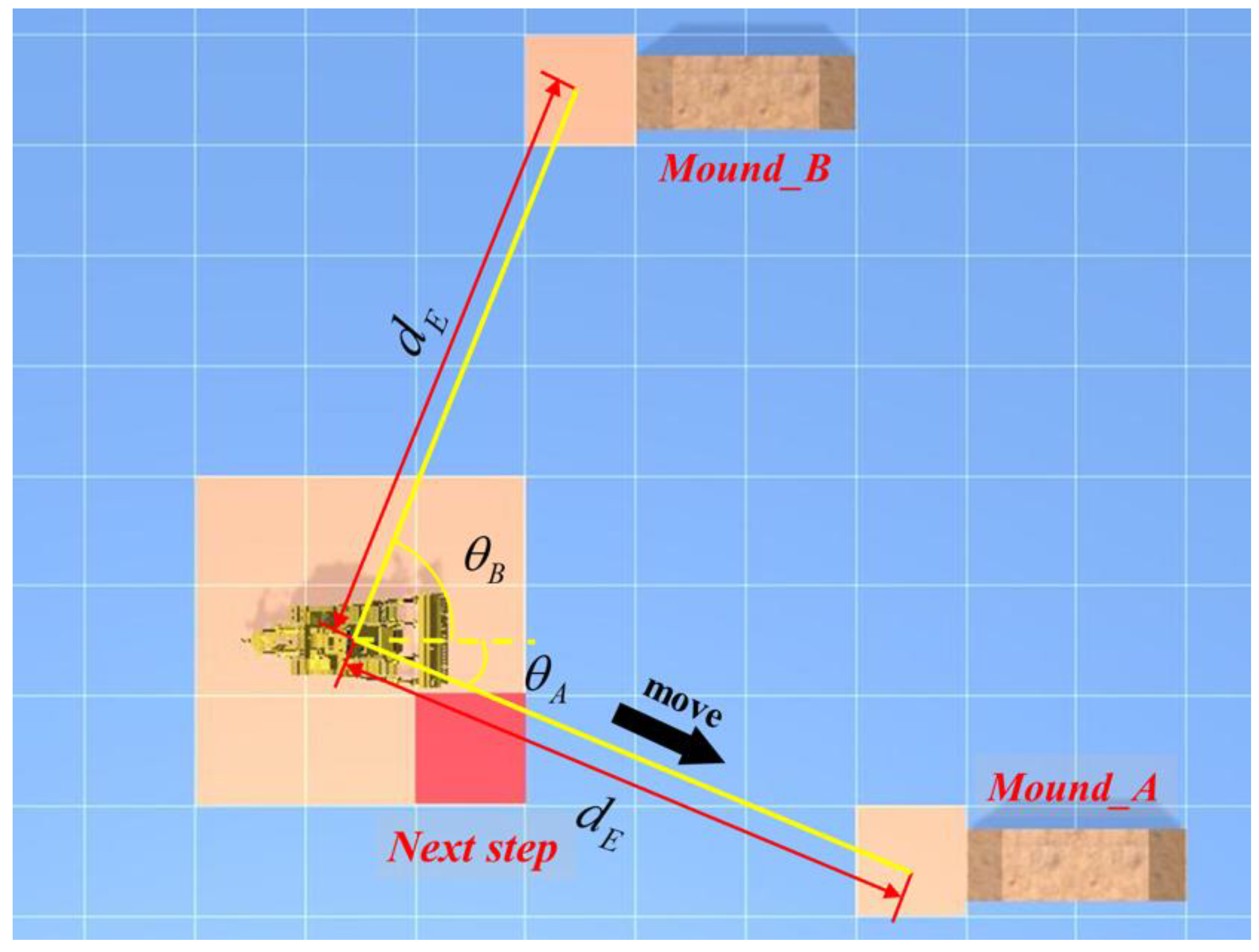
- A dynamic path planning method for optimising the paving quality indicators is proposed, and this method is embedded in the decision module for realising intelligent guidance and control. The conducted experiments demonstrate that this method effectively reduces the dependence of the paving operations on manual experience and establishes a high-precision event feed control method, which improves the quality of the paving and stabilises the construction efficiency at a high level.
- The dynamic assessment method is embedded in the action module of the OODA framework for dynamically evaluating the paving quality information of the entire area updated in real time, which improves the comprehensiveness and timeliness of the assessment. The experiments demonstrate that this dynamic assessment method can be used to comprehensively and effectively evaluate the paving quality during the construction process and provide guidance for quality control.
Author Contributions
Funding
Institutional Review Board Statement
Informed Consent Statement
Data Availability Statement
Acknowledgments
Conflicts of Interest
References
- Liu, D.; Sun, L.; Ma, H.; Cui, W. Process simulation and mesoscopic analysis of earth-rock dam compaction using discrete element method. Int. J. Geomech. 2020, 20, 04020047. [Google Scholar] [CrossRef]
- Zhong, D.; Liu, D.; Cui, B. Real-time compaction quality monitoring of high core earth-rock dam. Sci. China Technol. Sci. 2011, 54, 1906–1913. [Google Scholar] [CrossRef]
- Zhong, D.; Cui, B.; Liu, D.; Tong, D. Theoretical research on construction quality real-time monitoring and system integra-tion of core earth-rock dam. Sci. China 2009, 52, 3406–3412. [Google Scholar] [CrossRef]
- Zhong, D.; Du, R.; Cui, B.; Wu, B.; Guan, T. Real-time spreading thickness monitoring of high-core earth-rock dam based on k-nearest neighbor algorithm. Trans. Tianjin Univ. 2018, 24, 84–91. [Google Scholar] [CrossRef]
- Zhong, D.; Shi, M.; Cui, B.; Wang, J.; Guan, T. Research progress of intelligent dam construction. J. Hydraul. Eng. 2019, 50, 38–52, 61. [Google Scholar]
- Kim, S.; Lee, Y.; Sun, D.; Lee, S.; Yu, B.; Jang, S.; Kim, W.; Han, C. Development of bulldozer sensor system for estimating the position of blade cutting edge. Autom. Constr. 2019, 106, 102890.1–102890.11. [Google Scholar] [CrossRef]
- Liu, Q.; He, M.; Xu, D.; Ding, N.; Wang, Y. A mechanism for recognizing and suppressing the emergent behaviour of UAV swarm. Math. Probl. Eng. 2018, 2018, 6734923. [Google Scholar]
- Xie, D.; Yu, S.; Zhang, Y.; Tai, J.; Yu, Z. Information fusion applied in EV’s intelligent integrated station. Electr. Power Compon. Syst. 2019, 47, 1864–1876. [Google Scholar] [CrossRef]
- Hirayama, M.; Whitty, M.; Katupitiya, J.; Guivant, J. An optimized approach for automatic material distribution operations of bulldozers. Int. J. Adv. Robot. Syst. 2018, 15, 1–10. [Google Scholar] [CrossRef] [Green Version]
- Chang, G.K.; Mohanraj, K.; Stone, W.A.; Oesch, D.J.; Gallivan, V.L. Leveraging intelligent compaction and thermal profiling technologies to improve asphalt pavement construction quality: A case study. Transp. Res. Rec. J. Transp. Res. Board 2018, 2672, 48–56. [Google Scholar] [CrossRef]
- Yu, J.; Chen, F.; Peng, X.; Liu, G.; Deng, K.; Yu, X.; Zhang, W.; Mo, G.; Lu, X.; Chen, Z.; et al. Application of high toughness ultra-thin asphalt wear layer on artificial island passage of Hong Kong-Zhuhai-Macao bridge in Zhuhai. J. Tsinghua Univ. 2020, 60, 48–56. [Google Scholar]
- Daniel, V.C. Using Continuous Compaction Control Systems within an Earthwork Compaction Specification Framework. Master’s Thesis, University of Delaware, Newark, DE, USA, 27 June 2013. 19716. Available online: http://dspace.udel.edu/bitstream/handle/19716/12878/Daniel_Cacciola_thesis.pdf?sequence=1&isAllowed=y (accessed on 21 November 2021).
- Ahangaran, M.; Taghizadeh, N.; Beigy, H. Associative cellular learning automata and its applications. Appl. Soft Comput. 2017, 53, 1–18. [Google Scholar] [CrossRef]
- Beigy, H.; Meybodi, M.R. Cellular learning automata with multiple learning automata in each cell and its applications. IEEE Trans. Syst. Man Cybern. Part B Cybern. 2010, 40, 54–65. [Google Scholar] [CrossRef] [Green Version]
- Chen, Q.; Wang, Y. A cellular automata (CA) model for two-way vehicle flows on low-grade roads without hard separation. IEEE Intell. Transp. Syst. Mag. 2016, 8, 43–53. [Google Scholar] [CrossRef]
- Meybodi, M.; Beigy, H.; Taherkhani, M. Cellular learning automata and its applications. Sharif J. Sci. Technol. 2003, 19, 54–77. [Google Scholar]
- Zheng, Y.; Li, X.; Zhu, N.; Jia, B.; Jiang, R. Evacuation dynamics with smoking diffusion in three dimension based on an extended Floor-Field model. Phys. A Stat. Mech. Appl. 2018, 507, 414–426. [Google Scholar] [CrossRef]
- Roodposhti, M.S.; Aryal, J.; Bryan, B.A. A novel algorithm for calculating transition potential in cellular automata models of land-use/cover change. Environ. Model. Softw. 2019, 112, 70–81. [Google Scholar] [CrossRef]
- Wu, J.; Li, R.; Ding, R.; Li, T.; Sun, H. City expansion model based on population diffusion and road growth. Appl. Math. Model. 2017, 43, 1–14. [Google Scholar] [CrossRef]
- Khatibi, A.; Pourebrahim, S.; Mokhtar, M.B. Simulating carbon sequestration using cellular automata and land use assessment for Karaj, Iran. Solid Earth 2018, 9, 735–744. [Google Scholar] [CrossRef]
- Zhao, Y.; Jiang, W.; Li, S.; Ma, Y.; Su, G.; Lin, X. A cellular learning automata based algorithm for detecting community structure in complex networks. Neurocomputing 2015, 151, 1216–1226. [Google Scholar] [CrossRef]
- Esnaashari, M.; Meybodi, M.R. Deployment of a mobile wireless sensor network with k-coverage constraint: A cellular learning automata approach. Wireless Netw. 2013, 19, 945–968. [Google Scholar] [CrossRef]
- Beigy, H.; Meybodi, M.R. Cellular learning automata based dynamic channel assignment algorithms. Int. J. Comput. Intell. Appl. 2009, 8, 287–314. [Google Scholar] [CrossRef] [Green Version]
- Ruan, X.; Jin, Z.; Li, Y.; Tu, H. Dynamic cellular learning automata for evacuation simulation. IEEE Intell. Transp. Syst. Mag. 2019, 11, 129–142. [Google Scholar] [CrossRef]
- Wang, N.; Xu, H. Dynamics-constrained global-local hybrid path planning of an autonomous surface vehicle. IEEE Trans. Veh. Technol. 2020, 69, 6928–6942. [Google Scholar] [CrossRef]
- Osmankovic, D.; Tahirovic, A.; Magnani, G. All terrain vehicle path planning based on D* lite and MPC based planning paradigm in discrete space. In Proceedings of the IEEE International Conference on Advanced Intelligent Mechatronics (AIM), Sheraton Arabella Park Hotel, Munich, Germany, 3–7 July 2017; pp. 334–339. [Google Scholar]
- Hou, Y.; Liu, Y.; Lv, H.; Wu, Q.; Zhao, J.; Chen, Y. An autonomous navigation system of UAV based on binocular vision. J. Tianjin Univ. 2019, 52, 1262–1269. [Google Scholar]
- Shi, M.; Cui, B.; Wang, J.; Guan, T.; Tong, D.; Ren, B. Research on cooperative complete coverage path planning for unmanned roller group under complex construction conditions. J. Hydraul. Eng. 2020, 12, 1544–1557. [Google Scholar]
- Pan, Z.; Zhou, Y.; Zhao, C.; Hu, C.; Zhou, H.; Fan, Y. Assessment method of slope excavation quality based on point cloud data. KSCE J. Civ. Eng. 2019, 23, 935–946. [Google Scholar] [CrossRef]
- Huang, Y. Modelling and simulation method of the emergency response systems based on OODA. Knowl. Based Syst. 2015, 89, 527–540. [Google Scholar] [CrossRef]
- Ivkovic, D.; Ivkovic, S.; Milosavljevic, T.; Ivkovic, A. Boyd ooda loop and wilcoxon rank sum test in diagnostic procedures after major disasters with lung involvement. Eur. Respir. J. 2015, 46, PA1596. [Google Scholar]
- Manshad, M.K.; Meybodi, M.R.; Salajegheh, A. A new irregular cellular learning automata-based evolutionary computation for time series link prediction in social networks. Appl. Intell. 2020, 51, 71–84. [Google Scholar] [CrossRef]
- Khomami, M.M.D.; Rezvanian, A.; Meybodi, M.R. A new cellular learning automata-based algorithm for community detection in complex social networks. J. Comput. Sci. 2018, 24, 413–426. [Google Scholar] [CrossRef]
- Esnaashari, M.; Meybodi, M.R. Dynamic irregular cellular learning automata. J. Comput. Sci. 2018, 24, 358–370. [Google Scholar] [CrossRef]
- Zhang, X.; Jiao, L.; Oommen, B.J.; Granmo, O. A conclusive analysis of the finite-time behaviour of the discretized pursuit learning automaton. IEEE Trans. Neural Netw. Learn. Syst. 2020, 31, 284–294. [Google Scholar] [CrossRef]
- Mostafaei, H.; Chowdhury, M.U.; Obaidat, M.S. Border surveillance with WSN systems in a distributed manner. IEEE Syst. J. 2018, 12, 3703–3712. [Google Scholar] [CrossRef]
- Wang, J.; Zhong, D.; Adeli, H.; Wang, D.; Liu, M. Smart bacteria-foraging algorithm-based customized kernel support vector regression and enhanced probabilistic neural network for compaction quality assessment and control of earth-rock dam. Expert Syst. 2018, 35, e12357. [Google Scholar] [CrossRef]
- Hinas, A.; Roberts, J.M.; Gonzalez, F. Vision-based target finding and inspection of a ground target using a multirotor UAV system. Sensors 2017, 17, 2929. [Google Scholar] [CrossRef] [PubMed] [Green Version]
- Seppanen, H.; Virrantaus, K.; Kauppinen, T.; Fjader, C. Improving critical infrastructure resilience by identifying vulnerable interconnetions. Inj. Prev. 2016, 222, A46–A47. [Google Scholar] [CrossRef] [Green Version]
- Yarinezhad, R.; Hashemi, S.N. Distributed faulty node detection and recovery scheme for wireless sensor networks using cellular learning automata. Wireless Netw. 2019, 25, 2901–2917. [Google Scholar] [CrossRef]
- Mccaskill, J.S.; Packard, N.H. Analysing Emergent Dynamics of Evolving Computation in 2D Cellular Automata; Springer International Publishing: Cham, Switzerland, 2019; pp. 3–40. [Google Scholar]
- Pukkala, T. Optimized cellular automaton for stand delineation. J. For. Res. 2019, 30, 107–119. [Google Scholar] [CrossRef] [Green Version]
- Yazidi, A.; Bouhmala, N.; Goodwin, M. A team of pursuit learning automata for solving deterministic optimization problems. Appl. Intell. 2020, 50, 2916–2931. [Google Scholar] [CrossRef]
- Li, W.; Özcan, E.; John, R.A. Learning automata-based multiobjective hyper-heuristic. IEEE Trans. Evol. Comput. 2019, 23, 59–73. [Google Scholar] [CrossRef]
- Ghosh, M.; Kumar, R.; Saha, M.; Sikdar, B.K. Cellular automata and its applications. In Proceedings of the IEEE International Conference on Automatic Control and Intelligent Systems (I2CACIS), Shah Alam, Malaysia, 20 October 2018; pp. 52–56. [Google Scholar]
- Arrighi, P.; Bény, C.; Farrelly, T. A quantum cellular automaton for one-dimensional QED. Quantum Inf. Process. 2020, 19, 883. [Google Scholar] [CrossRef] [Green Version]
- M’manga, A.; Faily, S.; Mcalaney, J.; Williams, C.; Kadobayashi, Y.; Miyamoto, D. A normative decision-making model for cyber security. Inf. Comput. Secur. 2019, 26, 636–646. [Google Scholar] [CrossRef]
- Zhang, Q.; Liu, T.; Zhang, Z.; Huangfu, Z.; Li, Q.; An, Z. Compaction quality assessment of earth-rock materials using roller-integrated acoustic wave detection technique. Autom. Constr. 2019, 97, 110–121. [Google Scholar] [CrossRef]
- Alsalam, B.H.Y.; Morton, K.; Campbell, D.; Gonzalez, F. Autonomous UAV with vision based on-board decision making for remote sensing and precision agriculture. In Proceedings of the IEEE Aerospace Conference, Big Sky, MT, USA, 4–11 March 2017; pp. 1–12. [Google Scholar]
- Gong, W.; Xie, X.; Liu, Y. Human experience-inspired path planning for robots. Int. J. Adv. Robot. Syst. 2018, 15, 1–11. [Google Scholar] [CrossRef]
- Chaves, G.D.L.; Martins, L.G.A.; Oliveira, G.M.B. An improved model based on cellular automata for on-line navigation. In Proceedings of the Latin American Robotics Symposium (LARS) and 2017 Brazilian Symposium on Robotics (SBR), Curitiba, Brazil, 8–11 November 2017; pp. 1–6. [Google Scholar]
- Zhang, G.; Wang, Y.; Fan, Y.; Chen, C. Adaptive inverse control based on kriging algorithm and lyapunov theory of crawler electromechanical system. Complexity 2018, 2018, 1872943. [Google Scholar] [CrossRef]
- Liu, D.; Cui, B.; Liu, Y.; Zhong, D. Automatic control and real-time monitoring system for earth-rock dam material truck watering. Autom. Constr. 2013, 30, 70–80. [Google Scholar] [CrossRef]
- Lin, W.; Zhong, D.; Hu, W.; Lv, P.; Yan, Y.; Ren, B. Study on dynamic evaluation of compaction quality of earth rock dam based on random forest. J. Hydraul. Eng. 2018, 49, 945–955. [Google Scholar]
- Zheng, X.; Zhou, J.; Chen, G.; Chen, S. Exposure assessment for roller compacted concrete dam construction integrated real-time location information. KSCE J. Civ. Eng. 2020, 24, 703–714. [Google Scholar] [CrossRef]
- Li, X.; Yi, W.; Chi, H.; Wang, X.; Chan, A.P.C. A critical review of virtual and augmented reality (VR/AR) applications in construction safety. Autom. Constr. 2018, 86, 150–162. [Google Scholar] [CrossRef]
- Zhang, Q.; Liu, T.; Zhang, Z.; Huangfu, Z.; Li, Q.; An, Z. Unmanned rolling compaction system for earth-rock materials. Autom. Constr. 2019, 100, 103–117. [Google Scholar] [CrossRef]


| Type | Name | Area (m2) | Time (s) | Efficiency (m3/s) | Average Efficiency (m3/s) | Flatness | Average Flatness |
|---|---|---|---|---|---|---|---|
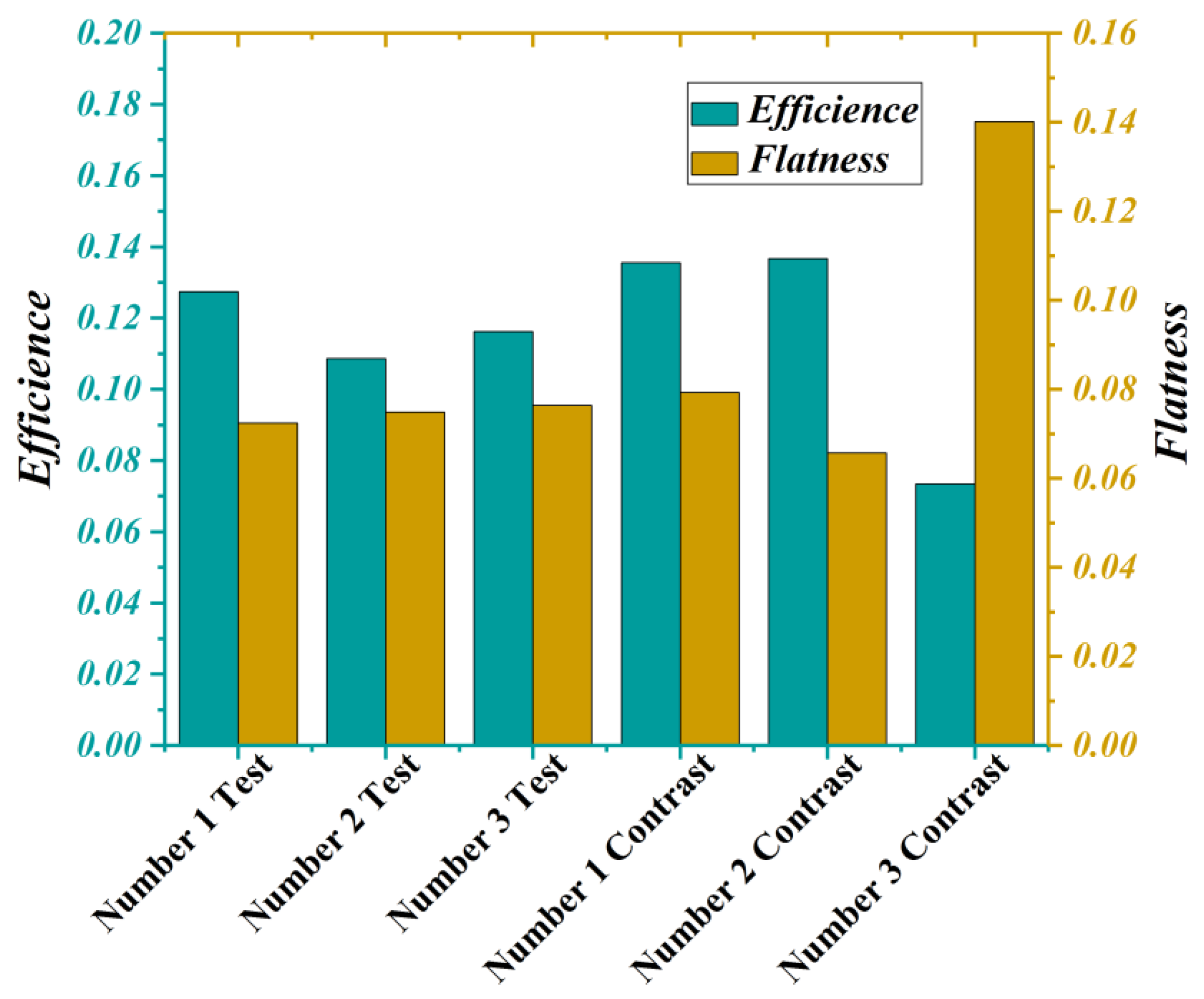
| Experimental group | Number 1 Test | 1360 | 2989 | 0.1274 | 0.1174 | 0.0724 | 0.0746 |
| Number 2 Test | 845 | 2178 | 0.1086 | 0.0749 | |||
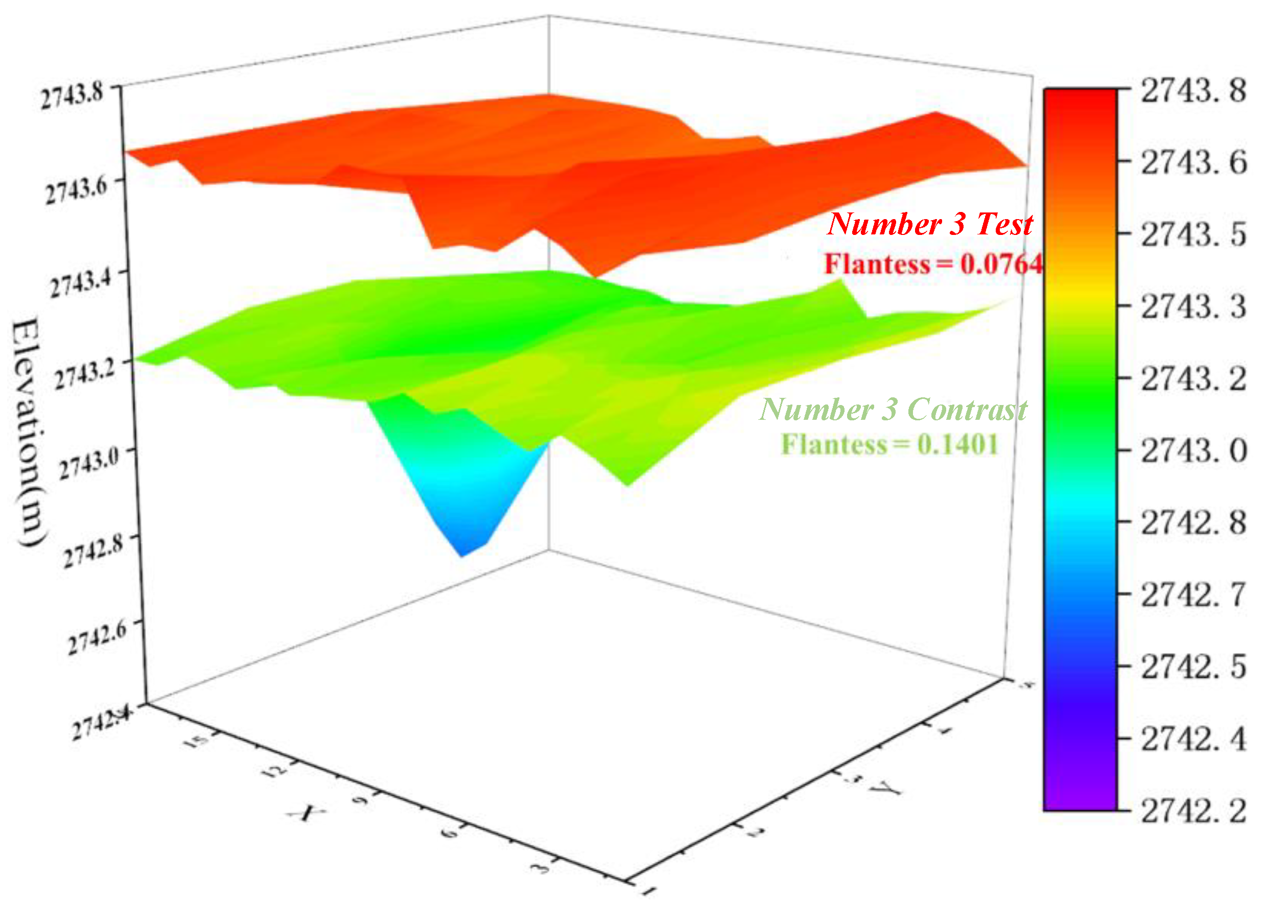
| Number 3 Test | 960 | 2314 | 0.1162 | 0.0764 | |||
| Contrast group | Number 1 Contrast | 1044 | 2081 | 0.1355 | 0.1152 | 0.0793 | 0.095 |
| Number 2 Contrast | 666 | 1315 | 0.1367 | 0.0657 | |||
| Number 3 Contrast | 891 | 3276 | 0.0734 | 0.1401 |
Publisher’s Note: MDPI stays neutral with regard to jurisdictional claims in published maps and institutional affiliations. |
© 2021 by the authors. Licensee MDPI, Basel, Switzerland. This article is an open access article distributed under the terms and conditions of the Creative Commons Attribution (CC BY) license (https://creativecommons.org/licenses/by/4.0/).
Share and Cite
Wang, C.; Wang, J.; Chen, W.; Yu, J.; Jiao, Z.; Yu, H. Assessment and Feedback Control of Paving Quality of Earth-Rock Dam Based on OODA Loop. Sensors 2021, 21, 7756. https://doi.org/10.3390/s21227756
Wang C, Wang J, Chen W, Yu J, Jiao Z, Yu H. Assessment and Feedback Control of Paving Quality of Earth-Rock Dam Based on OODA Loop. Sensors. 2021; 21(22):7756. https://doi.org/10.3390/s21227756
Chicago/Turabian StyleWang, Cheng, Jiajun Wang, Wenlong Chen, Jia Yu, Zheng Jiao, and Hongling Yu. 2021. "Assessment and Feedback Control of Paving Quality of Earth-Rock Dam Based on OODA Loop" Sensors 21, no. 22: 7756. https://doi.org/10.3390/s21227756