Article

A Novel Gold Film-Coated V-Shape Dual-Core Photonic Crystal Fiber Polarization Beam Splitter Covering the E + S + C + L + U Band

1
State Key Laboratory of Information Photonics and Optical Communications, Beijing University of Posts and Telecommunications, Beijing 100876, China
2
Research Center for Convergence Networks and Ubiquitous Services, University of Science & Technology Beijing (USTB), Beijing 100083, China
3
Photonics Research Centre, Department of Electronic and Information Engineering, The Hong Kong Polytechnic University, Hung Hom, Hong Kong
4
Department of Physics and Electrical Engineering, Northumbria University, Newcastle upon Tyne NE1 8ST, UK
5
Key Laboratory of Nondestructive Test (Ministry of Education), Nanchang Hangkong University, Nanchang 330063, China
*
Author to whom correspondence should be addressed.
Sensors 2021, 21(2), 496; https://doi.org/10.3390/s21020496
Submission received: 13 November 2020 / Revised: 20 December 2020 / Accepted: 7 January 2021 / Published: 12 January 2021
(This article belongs to the Special Issue Advanced Fiber Photonic Devices and Sensors)

Abstract

:
In this paper, a novel gold film-coated V-shape dual-core photonic crystal fiber (V-DC-PCF) polarization beam splitter (PBS) based on surface plasmon resonance effect is proposed. The coupling lengths of the X-polarization (X-pol) and Y-polarization (Y-pol) and the corresponding coupling length ratio of the proposed V-DC-PCF PBS without gold film and with gold film are compared. The fiber structure parameters and thickness of the gold film are optimized through investigating their effects on the coupling lengths and coupling length ratio. As the propagation length increases, the normalized output powers of the X-pol and Y-pol of the proposed V-DC-PCF PBS at the three wavelengths 1.610, 1.631, and 1.650 μ m are demonstrated. The relationships between the extinction ratio ( E R ), insertion loss ( I L ) and wavelength for the three splitting lengths ( S L s ) 188, 185, and 182 μ m are investigated. Finally, it is demonstrated that for the proposed V-DC-PCF PBS, the optimal S L is 188 μ m , the I L s of the X-pol and Y-pol are less than 0.22 dB, and the splitting bandwidth ( S B ) can cover the E + S + C + L + U band. The proposed V-DC-PCF PBS has the ultra-short S L , ultra-wide S B , and ultra-low I L , so it is expected to have important applications in the laser, sensing, and dense wavelength division multiplexing systems.

1. Introduction

Since the first photonic crystal fiber (PCF) was fabricated by Russell et al. in 1996 [1], PCFs have been investigated extensively and applied in different optical fields, such as fiber laser, sensing, optical communication, and so on [2,3,4,5,6,7,8]. At present, the PCF-based optical devices, including polarization beam splitter (PBS), polarization filter, modulator, etc., have become the indispensable components in the all-fiber optical systems [9,10,11,12,13,14].
In recent years, the dual-core PCF (DC-PCF) PBS based on the coupled mode theory has been widely investigated [15,16,17,18,19]. In 2016, Zi et al. reported a simple DC-PCF PBS, whose splitting lengths ( S L s ) are 249 and 506 μ m and splitting bandwidths ( S B s ) are 17 and 12 nm at wavelengths 1.55 and 1.31 μ m , respectively [20]. In the same year, Wang et al. proposed a liquid crystal-filled DC-PCF PBS, whose S L is 890.5 μ m and S B covers the S + C + L band [21]. In 2017, He et al. designed an octagonal lattice DC-PCF PBS with the five elliptical air holes, whose S L is 105 μ m and S B covers the S + C + L band [22]. In 2017, Wang et al. demonstrated a surface plasmon resonance (SPR) effect-based DC-PCF PBS filled with elliptical gold wire, whose S L is 1.079 mm and S B only covers the C band [23]. In 2018, Wang et al. achieved a short DC-PCF PBS with the liquid filled in the central and two elliptical air holes, whose S L is 78 μ m and S B only covers the C band [24]. In 2019, Lou et al. investigated an ultrashort SPR effect-based DC-PCF PBS coated with gold film, whose S L is only 47.26 μ m and S B cannot cover the C band [25]. From the previous works, the performances of the DC-PCF PBS can be obviously improved by introducing the elliptical air holes, changing the lattice arrangement of air holes, and selectively filling or coating the air holes with the liquid crystal, liquid, metal wire, and metal film.
Up to now, the fabrication technology of the PCFs with the circular air holes arranged in a hexagonal lattice has been developed more mature [26,27,28,29,30,31,32]. Many fabrication methods have been reported, including stack-and-draw, 3D printing, femtosecond laser drilling, etc. [33,34,35,36,37,38,39]. In contrast, it is more difficult to fabricate the PCFs when the air holes are arranged in the rectangle and octagonal shapes or the elliptical air holes exist. Especially when selectively filling the metal wire or coating the metal film into the air holes of the PCFs, the difficulty of fabrication is further increased. Since Sazio et al. and Russell et al. Firstly demonstrated the gold film-coated PCF in 2006 [40] and gold wire-filled PCF in 2008 [41], respectively, there are some reports on fabricating the gold film-coated and gold wire-filled PCFs by different methods [42,43,44,45,46,47,48]. At present, it is becoming a research hotspot to design and fabricate the gold film-coated or gold wire-filled DC-PCF PBS which has the hexagonal arrangement of circular air holes.
In this paper, we propose a novel gold film-coated V-shape DC-PCF (V-DC-PCF) PBS based on the SPR effect. We compare the coupling lengths ( C L s ) of the X-polarization (X-pol) and Y-polarization (Y-pol) and the coupling length ratio ( C L R ) when the proposed V-DC-PCF PBS is coated with and without gold film. At the three wavelengths 1.610, 1.631, and 1.650 μ m , the normalized output powers of the X-pol and Y-pol of the V-DC-PCF PBS are demonstrated when the propagation length increases. For the three splitting lengths ( S L s ) 188, 185, and 182 μ m , the extinction ratio ( E R ) and insertion loss ( I L ) of the proposed V-DC-PCF PBS are investigated. Finally, we obtain a V-DC-PCF PBS with good performances, whose optimal S L s is 188 μ m , I L s of the X-pol and Y-pol are less than 0.22 dB, and S B can cover the E + S + C + L + U band.

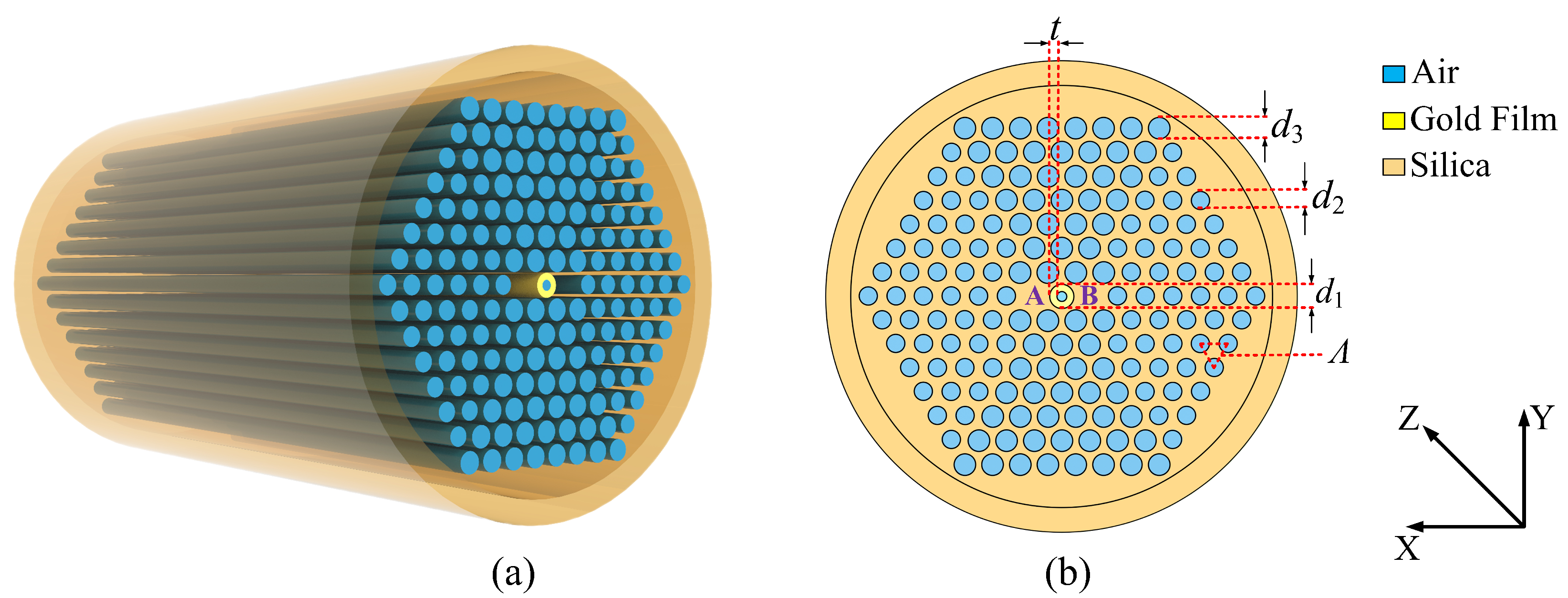
2. Design of the V-DC-PCF PBS

The three-dimensional and cross-sectional structures of the proposed V-DC-PCF PBS are shown in Figure 1a,b, respectively. From Figure 1a,b, the substrate material is silica, the air holes are arranged in a hexagonal lattice, and the hole to hole pitch is Λ . The most central air hole with the diameter of d 1 is coated with the gold film, which has a thickness of t. When the light energy is propagated inside the V-DC-PCF coated with gold film, the free electrons on the gold film surface interact with the incident light field, generating the SPR and exciting the surface plasmon polariton (SPP) mode on the gold film surface. At a specific wavelength, the core mode of the V-DC-PCF and SPP mode have the same propagation constant, so the mode coupling occurs due to the phase-matching condition. The two air holes in the first layer along the X-direction of the V-DC-PCF are missing to form the two cores, which are labeled as the cores A and B, respectively. In the cladding region of the V-DC-PCF, there are two other sizes of air holes. The diameter of the smaller air holes on the left and right sides is d 2 , and the diameter of the larger air holes on the upper and lower sides is d 3 . In practice, such a V-DC-PCF can be fabricated with the stack-and-draw method, and the gold film can be selectively coated on the most central air hole by the chemical vapor deposition or magnetron sputtering technique [33,40,47].
The material dispersion of the silica can be obtained by the Sellmeier equation as [49]
n 2 ( λ ) = 1 + A 1 λ 2 λ 2 B 1 2 + A 2 λ 2 λ 2 B 2 2 + A 3 λ 2 λ 2 B 3 2
where λ is the wavelength of free space. The related parameters of the Sellmeier equation for the silica material are shown in Table 1.
The relative dielectric constant of the gold material can be described by the Drude-Lorentz model [50]
ε m = ε ω D 2 ω ( ω j γ D ) Δ ε · Ω L 2 ( ω 2 Ω L 2 ) j Γ L ω
where ω is the angle frequency of the guided-wave, ε and Δ ε are the high frequency dielectric constant and weighted coefficient, ω D and γ D are the plasma and damping frequencies, and Ω L and Γ L are the frequency and bandwidth of the Lorentz oscillator, respectively. The specific parameters of the Drude-Lorentz model for the gold material are shown in Table 2.
The C L s in the X-pol and Y-pol directions of the V-DC-PCF PBS can be described as [51]
C L X = λ 2 ( n e v e n X n o d d X )
C L Y = λ 2 ( n e v e n Y n o d d Y )
where C L X and C L Y represent the C L of the X-pol and Y-pol, respectively, λ is the wavelength of the initial incident light, and n e v e n X , n o d d X , n e v e n Y , and n o d d Y represent the effective refractive indices (ERIs) of the even and odd modes in the X-pol and Y-pol, respectively.
The C L R can be calculated by [52]
C L R = C L Y C L X
When the C L R = 2 or 1/2, the optimal S L can be obtained.
For the proposed V-DC-PCF PBS, we only need to consider the case that the initial incident light enters the core A or B since the geometric structure of the cores A and B are identical and symmetrical. In this work, when supposing that the initial incident light entering the core A, the output powers P out of the X-pol and Y-pol in the core A can be described as [53]
P out , A X , Y = P i n cos 2 ( π 2 P L C L X , Y )
where P in is the power of the initial incident light, and P L is the propagation length inside the V-DC-PCF PBS.
The E R of the core A, which is considered as a significant parameter for evaluating the splitting performance of the V-DC-PCF PBS, can be calculated by [54]
E R A = 10 lo g 10 P o u t , A X P o u t , A Y
The I L of the X-pol and Y-pol in the core A of the V-DC-PCF PBS can be described as [55]
I L X , Y = 10 lo g 10 P o u t , A X , Y P i n

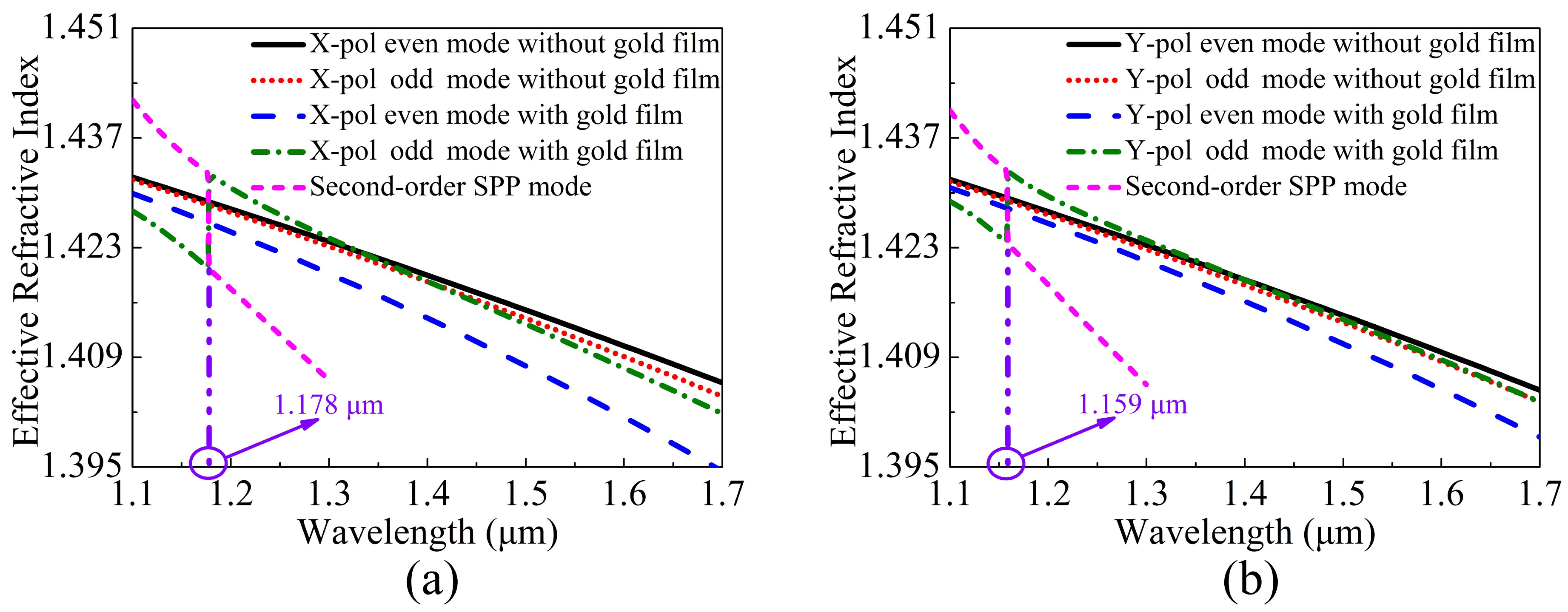
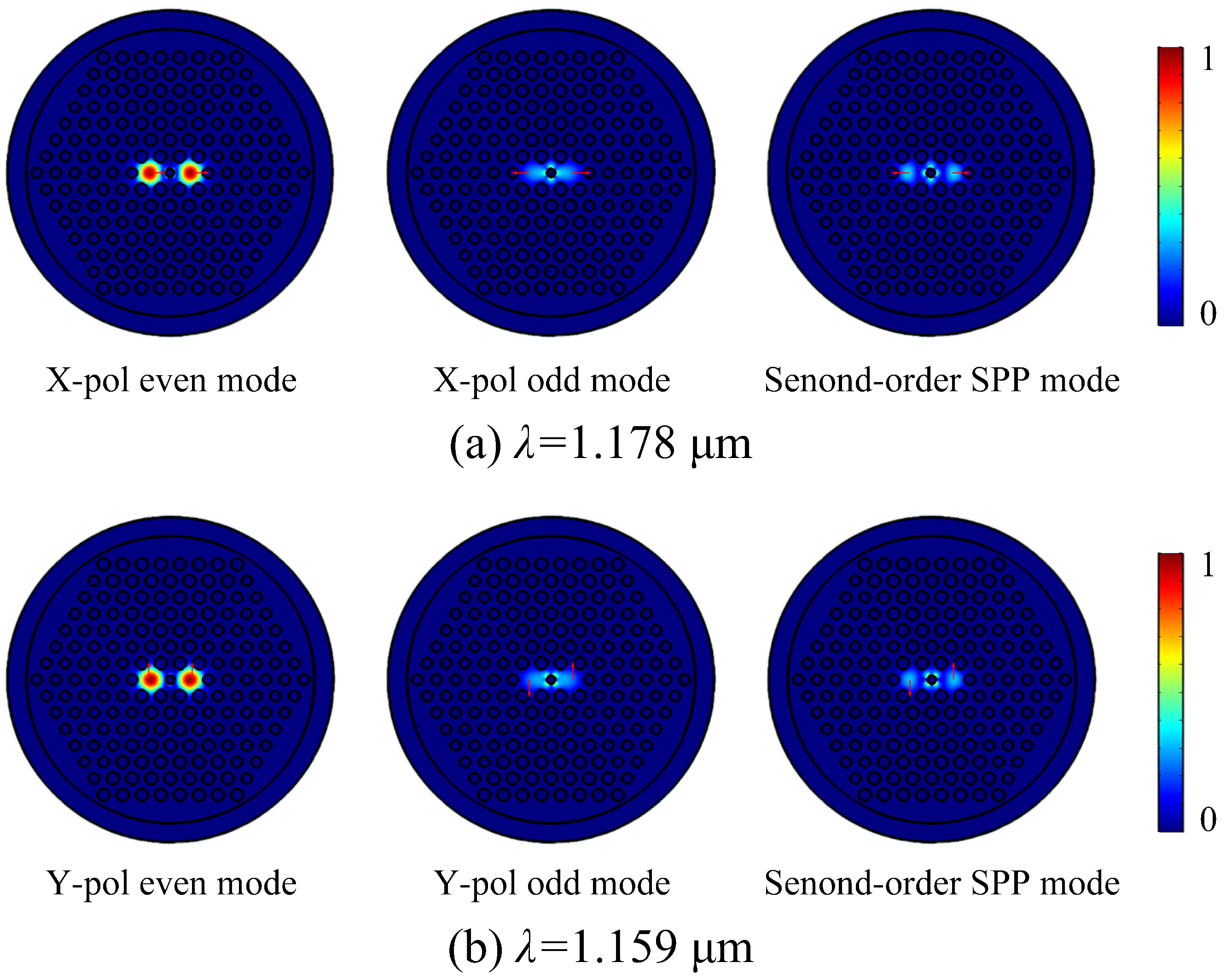
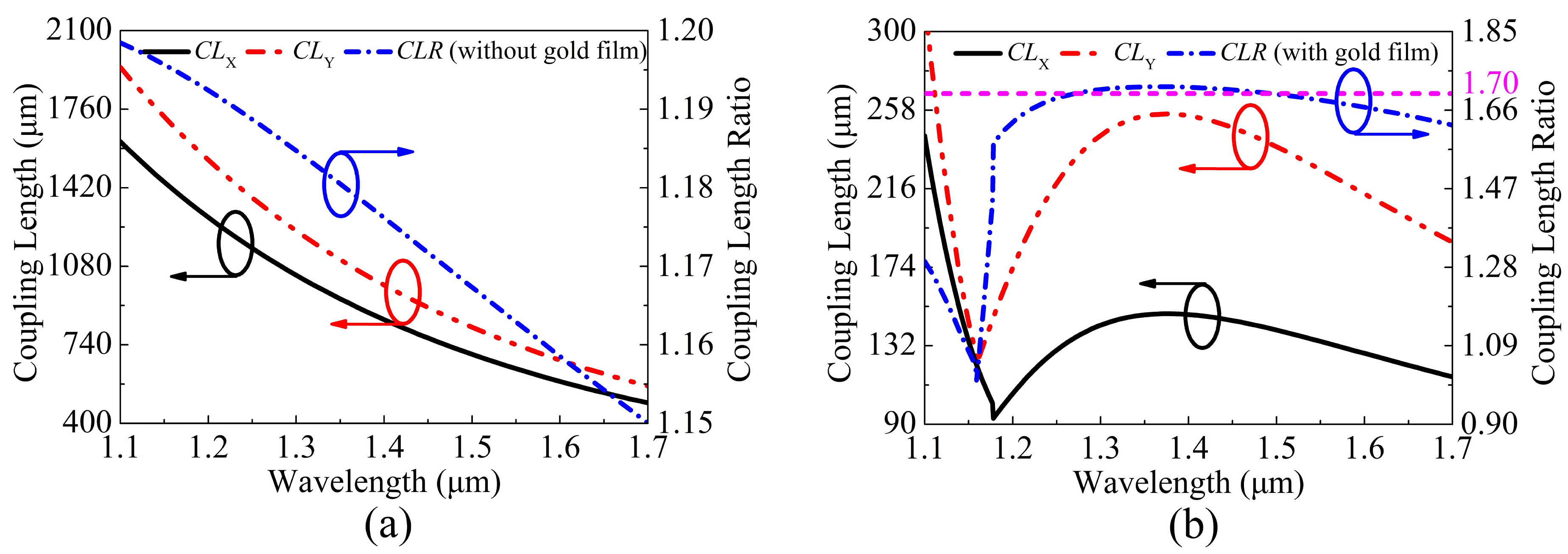
3. Simulation Results and Discussion

The finite element method is used to investigate the propagation characteristics of the proposed V-DC-PCF [56,57]. The initial fiber structure parameters are set as following: d 1 = 0.95 μ m , d 2 = 1.20 μ m , d 3 = 1.40 μ m , Λ = 2.20 μ m , and t = 55 nm. In the simulation, the material coefficients including the refractive indices of the silica and air and the relative dielectric constant of the gold material are set after the simulation model is established. Then, a perfect matching layer (PML), whose thickness is 10 μ m and refractive index is n silica +0.03, is added to the outermost edge of the gold film-coated V-DC-PCF so as to absorb the radiation energy [58]. Moreover, the grid sizes of the silica, air holes, and PML are set as λ / 4 , and the grid size of the most central air hole coated with gold film is set as λ / 6 .
When the V-DC-PCF is coated without gold film and with gold film, the ERIs of the X-pol and Y-pol even and odd modes and second-order SPP mode are shown in Figure 2a,b, respectively. It can be seen from Figure 2a,b that for the V-DC-PCF without gold film, the ERIs of the X-pol and Y-pol even and odd modes decrease approximately linearly with the increase of wavelength. Moreover, the ERIs of the X-pol and Y-pol odd modes decrease more obviously than that of the X-pol and Y-pol even modes at the longer wavelength side, but the differences between the X-pol or Y-pol even and odd modes are very small. According to Equations (3) and (4), we can infer that the C L X and C L Y will also change in the approximately linear trend and have large values. In contrast, when the V-DC-PCF is coated with gold film, the ERIs of the X-pol and Y-pol even modes still decrease approximately linearly as the wavelength increases. However, there are two cross points between the ERIs of the X-pol and Y-pol odd modes and second-order SPP mode at wavelengths 1.178 and 1.159 μ m , respectively, where the phase-matching condition is satisfied. According to the coupled mode theory, the X-pol and Y-pol odd modes occur to couple with the second-order SPP mode at wavelengths 1.178 and 1.159 μ m , respectively. In addition, it can be seen from Figure 2a,b that before the phase-matching wavelengths, the ERIs of the X-pol and Y-pol odd modes decrease rapidly, along with a relatively small and stable slope. Hence, the differences between the ERIs of the X-pol and Y-pol even and odd modes increase rapidly with the increase of wavelength. The ERIs of the X-pol and Y-pol odd modes increase significantly at wavelengths 1.178 and 1.159 μ m , respectively, and there are maximum differences between the ERIs of the X-pol and Y-pol even and odd modes. Thus, the C L X and C L Y will have significant changes at wavelengths 1.178 and 1.159 μ m , respectively. But after the phase-matching wavelengths, the ERIs of the X-pol and Y-pol odd modes first decrease rapidly and then maintain a relatively stable slope. Finally, the relatively stable slope of the ERIs of the X-pol and Y-pol odd modes will be smaller than that of the ERIs of the X-pol and Y-pol even modes as the wavelength increases. Therefore, the differences between the ERIs of the X-pol and Y-pol even and odd modes first decrease and then increase as the wavelength increases. Figure 3a,b show the mode field distributions of the X-pol and Y-pol even and odd modes and second-order SPP mode calculated at wavelengths 1.178 and 1.159 μ m , respectively. From Figure 3a,b, the mode field distributions of the X-pol and Y-pol even modes have no change at wavelengths 1.178 and 1.159 μ m , respectively. But the mode field energies of the X-pol and Y-pol odd modes and second-order SPP mode occur to transfer at the two wavelengths. It further confirms the previous conclusion that only the X-pol and Y-pol odd modes and second-order SPP mode occur to couple at the phase-matching wavelengths.
The relationships between the C L X , C L Y , and C L R and wavelength are shown in Figure 4a,b, respectively, when the V-DC-PCF is coated without gold film and with gold film. It can be seen from Figure 4a that when the V-DC-PCF is coated without gold film, the C L X and C L Y decrease gradually, and the corresponding C L R also decreases in an approximately linear trend as the wavelength increases. According to Equations (3) and (4) and the above analysis, when the V-DC-PCF is coated with gold film, the C L X and C L Y decrease rapidly before the phase-matching wavelengths, and occur to change significantly at wavelengths 1.178 and 1.159 μ m , respectively, as shown in Figure 4b. After the phase-matching wavelengths, the C L X and C L Y increase first and then decrease. At this time, according to Equation (5), the C L R decreases rapidly before wavelength 1.159 μ m , has a significant change between wavelength 1.159 and 1.178 μ m , and increases first and then decreases after wavelength 1.178 μ m . However, after wavelength 1.178 μ m , the overall change of the C L R is relatively flat. In addition, the C L R has the two intersections, where the C L R is equal to 1.7. By comparing Figure 4a,b, the maximum C L for the V-DC-PCF with gold film is smaller than the minimum C L for the V-DC-PCF without gold film, which has a direct effect on the S L of the V-DC-PCF PBS. From the above analysis, it is possible to achieve a PBS with the shorter S L and larger S B by using a V-DC-PCF with gold film.
The structure parameters of the proposed V-DC-PCF PBS with gold film need to be optimized to satisfy the condition of C L R = 2, which corresponds to the optimal S L . When the fiber structure parameters, including d 1 , d 2 , d 3 , Λ , and t are changed, respectively, the ERIs of the X-pol and Y-pol even and odd modes will occur to change in different degrees, which can also cause the changes of the C L X , C L Y , and C L R . The variations of the C L X , C L Y , and C L R of the proposed V-DC-PCF PBS are shown in Figure 5a,b when d 1 is chosen as 0.90, 0.95, and 1.00 μ m , respectively. It can be seen from Figure 5a that the C L X and C L Y decrease as d 1 increases at the short wavelength side. At the long wavelength side, as d 1 increases, the C L X still decreases slightly, while the C L Y shows a slightly increased trend. The C L R gradually increases as d 1 increases, and the phase-matching wavelength occurs to red-shift, as shown in Figure 5b.
The variations of the C L X , C L Y , and C L R of the proposed V-DC-PCF PBS are shown in Figure 6a,b when d 2 is chosen as 1.00, 1.20, and 1.40 μ m , respectively. It can be seen from Figure 6a,b that as d 2 increases, the C L X and C L Y gradually decrease while the C L R shows an increased trend. In addition, the change of the phase-matching wavelength is not obvious, and only a slight red-shift occurs as d 2 increases.
When d 3 is chosen as 1.20, 1.40, and 1.60 μ m , respectively, the variations of the C L X , C L Y , and C L R of the proposed V-DC-PCF PBS are shown in Figure 7a,b. From Figure 7a, as d 3 increases, the C L X decreases slightly at the short wavelength side and remains nearly unchanged at the long wavelength side. In comparison, the C L Y gradually increases as d 3 increases, and the corresponding change amplitude at the long wavelength side is larger than that at the short wavelength side. As shown in Figure 7b, as d 3 increases, the C L R gradually increases, and the position of the phase-matching wavelength remains unchanged.
The variations of the C L X , C L Y and C L R of the proposed V-DC-PCF PBS are shown in Figure 8a,b when Λ is chosen as 2.1, 2.2, and 2.3 μ m , respectively. Figure 8a,b, as Λ increases, the C L X and C L Y gradually increase, but the C L R shows a decreasing trend. In addition, the change of the phase-matching wavelength is not obvious, along with a small shift towards the short wavelength side. By comparing the results shown in Figure 5b, Figure 6b, Figure 7b, and Figure 8b, it is found that the change of Λ has the most remarkable influence on the C L R .
Figure 9a,b show the variations of the C L X , C L Y , and C L R of the proposed V-DC-PCF PBS when t is chosen as 45, 55, and 65 nm, respectively. It can be seen from Figure 9a that as t increases, the C L X and C L Y increase at the short wavelength side and decrease at the long wavelength side. It can be seen from Figure 9b that as t increases, the C L R increases at the short wavelength side and decreases at the long wavelength side, and the position of the phase-matching wavelength gradually shifts towards the short wavelength side.
Based on the above analysis, the influence rule of the structure parameters of the proposed V-DC-PCF PBS on the C L X , C L Y , and C L R can be clearly known. Thus, the empirical steps for designing such a V-DC-PCF PBS can be summarized as following. First, by together adjusting d 1 and t, the phase-matching condition can be achieved at the shorter wavelength, and the value of the C L R is close to 2. At this time, a relatively flat C L R curve can be obtained in the desired band. Second, by together adjusting d 2 , d 3 , and Λ , the C L R curve with the relatively flat profile and the value of 2 can be obtained when the phase-matching wavelength does not change obviously. Thus, the optimized structure parameters of the proposed V-DC-PCF PBS are chosen as follows: d 1 = 1.00 μ m , d 2 = 1.41 μ m , d 3 = 1.50 μ m , Λ = 2.10 μ m , and t = 46.5 nm. At this time, the variations of the optimal C L X , C L Y , and C L R of the proposed V-DC-PCF PBS and the corresponding zoomed flat region of the C L R are shown in Figure 10a,b, respectively. From Figure 10a, the C L X and C L Y have significant changes at the phase-matching wavelengths 1.277 and 1.243 μ m , respectively. Moreover, the C L R is approximately equal to 2 in a wide wavelength range of above 1.277 μ m . From Figure 10b, the value of the C L R changes from 1.974 to 2.051 in the wavelength range from 1.32 to 1.68 μ m , and the maximum difference of the C L R between wavelength 1.32 and 1.68 μ m is 0.077. In addition, the values of the C L R at wavelengths 1.610, 1.631, and 1.650 μ m are 2.01, 2.00, and 1.99, respectively, which are approximately equal to 2. It is worth noting that although the value of the C L R is also equal to 1.99, 2.00, and 2.01 at other three shorter wavelengths, but the corresponding slope variation of the C L R is larger, which will affect the overall bandwidth to a great extent.
In the following, the relationships between the output powers P o u t of the X-pol and Y-pol of the proposed V-DC-PCF PBS and P L at the three wavelengths 1.610, 1.631, and 1.650 μ m are shown in Figure 11a–c, respectively. From Figure 11a–c, P o u t of the X-pol reaches the maximum values when the P L is located at 188, 185, and 182 μ m , respectively. In contrast, the corresponding P o u t of the Y-pol reaches 0 when the P L is located at 188, 185, and 182 μ m , respectively. This phenomenon indicates that the X-pol light only exists in the core A while the Y-pol light only exists in the core B at the three P L s . Therefore, the S L of the proposed V-DC-PCF PBS may be 182, 185, or 188 μ m . Moreover, another notable phenomenon is that the total P o u t decreases slightly as the P L increases. This is mainly because a fraction of the energy always propagates on the surface of the gold film, leading to the increase of the ohmic loss.
When the S L is equal to 182, 185, and 188 μ m , respectively, the relationships between the E R s in the core A of the proposed V-DC-PCF PBS and wavelength are shown in Figure 12. It can be seen from Figure 12 that for the S L s of 182 and 185 μ m , the E R s are less than 20 dB in some wavelength ranges. In contrast, when S L is equal to 188 μ m , the E R is always larger than 20 dB in a wide wavelength range from 1.359 to 1.677 μ m . Figure 13 shows the relationships between the I L s of the X-pol and Y-pol in the core A of the proposed V-DC-PCF PBS and wavelength when the S L is equal to 182, 185, and 188 μ m , respectively. From Figure 13, for the S L s of 182, 185, and 188 μ m , the maximum I L of the X-pol and Y-pol is 0.22 dB in the wavelength range of 1.359 to 1.677 μ m . Such a small I L can meet the actual application requirements. Because the proposed V-DC-PCF PBS has the ultra-short S L , the bending loss can be neglected. Therefore, we can draw a conclusion that for the proposed V-DC-PCF PBS, the optimal S L is 188 μ m , the S B covers the entire E + S + C + L + U band, and the I L s of the X-pol and Y-pol are less than 0.22 dB.
The comparisons between the proposed V-DC-PCF PBS and reported SPR-based DC-PCF PBS are shown in Table 3. From Table 3, only the S B of the SPR-based DC-PCF PBS reported in Ref [12] is larger than that of the proposed V-DC-PCF PBS. However, in Ref [12], the S L and minimum I L are 4.036 mm and 0.8 dB, respectively, while they are only 188 μ m and 0.22 dB in this work. Moreover, the air holes of the DC-PCF PBS reported in Ref [12] are arranged in a square lattice, so it is difficult to fabricate. In addition, only the S L of the SPR-based DC-PCF PBS reported in Ref [25] is shorter than that of this work. However, in Ref [25], the S B , which covers the S + C + L band, is much narrower than that of this work, and the I L is not given. Moreover, the air holes of square lattice of the DC-PCF PBS reported in Ref [25] also increase the difficulty of fabrication. In summary, the proposed V-DC-PCF PBS has the good comprehensive performances.
The E R s in the core A and I L s of the X-pol and Y-pol in the core A of the proposed V-DC-PCF PBS are shown in Figure 14a,b when t changes ± 1 % . From Figure 14a, the wavelength range of the E R larger than 20 dB changes slightly, which indicates that the proposed V-DC-PCF PBS still has a wide S B . From Figure 14b, the I L s of the X-pol and Y-pol are always less than 0.22 dB in each S B . Thus, t has good error-tolerant rate in the actual coating process.

4. Conclusions

In summary, a novel gold film-coated V-DC-PCF PBS based on the SPR effect is proposed. The C L X , C L Y , and C L R of the proposed V-DC-PCF PBS coated without gold film and with gold film are investigated. The empirical steps for designing such a V-DC-PCF PBS are summarized by analyzing the effects of the fiber structure parameters on the C L X , C L Y , and C L R . The C L R of 2 can be obtained at the three wavelengths 1.610, 1.631, and 1.650 μ m . When the S L s are equal to 188, 185, and 182 μ m , the relationships between the E R , I L and wavelength are investigated, respectively. The proposed V-DC-PCF PBS has the good comprehensive performances, including the S L of 188 μ m , I L of less than 0.22 dB, and S B of covering the E + S + C + L + U band. It is believed that the proposed V-DC-PCF PBS can find important applications in the laser, sensing, and dense wavelength division multiplexing systems.

Author Contributions

Y.Q.: Conceptualization, Formal analysis, Writing-original draft, Methodology and Investigation. J.Y.: Supervision, Formal analysis, Methodology, Writing-review and editing. S.Q.: Supervision, Formal analysis, Writing-review and editing. X.Z.: Supervision, Formal analysis, Writing-review and editing. F.L.: Formal analysis, Writing-review and editing. B.Y.: Formal analysis, Writing-review and editing. Q.W.: Supervision, Formal analysis, Methodology, Writing-review and editing. K.W.: Formal analysis, Writing-review and editing. X.S.: Supervision, Writing-review and editing. K.L.: Supervision, Writing-review and editing. C.Y.: Supervision, Writing-review and editing. All authors have read and agreed to the published version of the manuscript.

Funding

This research was funded by National Key Research and Development Project of China (2019YFB2204001).

Acknowledgments

We thank the State Key Laboratory of Information Photonics and Optical Communications (Beijing University of Posts and Telecommunications of China) for the scientific helps and supports throughout this research.

Conflicts of Interest

The authors declare no conflict of interest.

References

  1. Knight, J.C.; Birks, T.A.; Russell, P.S.J.; Atkin, D.M. All-silica single-mode optical fiber with photonic crystal cladding. Opt. Lett. 1996, 21, 1547–1549. [Google Scholar] [CrossRef]
  2. Liu, Q.; Ma, Z.; Wu, Q.; Wang, W.L. The biochemical sensor based on liquid-core photonic crystal fiber filled with gold, silver and aluminum. Opt. Laser Technol. 2020, 130, 106363. [Google Scholar] [CrossRef]
  3. Úsuga-Restrepo, J.E.; Guimarães, W.M.; Franco, M.A.R. All-fiber circular polarization beam splitter based on helically twisted twincore photonic crystal fiber coupler. Opt. Laser Technol. 2020, 58, 102285. [Google Scholar]
  4. Feng, X.X.; Du, H.J.; Li, S.G.; Zhang, Y.N.; Liu, Q.; Gao, X.Y. A polarization filter based on photonic crystal fiber with asymmetry around gold-coated holes. Plasmonics 2018, 13, 1271–1275. [Google Scholar] [CrossRef]
  5. Yu, R.W.; Chen, Y.X.; Shui, L.L.; Xiao, L.M. Hollow-core photonic crystal fiber gas sensing. Sensors 2020, 20, 2996. [Google Scholar] [CrossRef]
  6. Yao, C.Y.; Xiao, L.M.; Gao, S.F.; Wang, Y.Y.; Wang, P.; Kand, R.F.; Jine, W.; Rena, W. Sub-ppm CO detection in a sub-meter-long hollow-core negative curvature fiber using absorption spectroscopy at 2.3 μm. Sens. Actuat. B Chem. 2020, 303, 127238. [Google Scholar] [CrossRef]
  7. Wang, J.; Pei, L.; Wang, J.S.; Ruan, Z.L.; Zheng, J.J.; Li, J.; Ning, T.G. Magnetic field and temperature dual-parameter sensor based on magnetic fluid materials filled photonic crystal fiber. Opt. Express 2020, 28, 1456–1471. [Google Scholar] [CrossRef]
  8. Shakya, A.K.; Singh, S. Design of dual polarized tetra core PCF based plasmonic RI sensor for visible-IR spectrum. Opt. Commun. 2021, 478, 126372. [Google Scholar] [CrossRef]
  9. Chu, L.H.; Liu, M.; Shum, P.; Fu, Y.B. Simultaneous achievement of an ultrashort length and a high extinction ratio polarization splitter based on the dual-core photonic crystal fiber with Ge20Sb15Se65 glass. Appl. Opt. 2019, 58, 7892–7896. [Google Scholar] [CrossRef]
  10. Rahman, M.M.; Khaleque, A.; Rahman, M.T.; Rabbi, F. Gold-coated photonic crystal fiber based polarization filter for dual communication windows. Opt. Commun. 2020, 461, 125293. [Google Scholar] [CrossRef]
  11. Reyes-Vera, E.; Úsuga-Restrepo, J.; Gomez, F.; Gómez-Cardona, N. Novel multiband polarization beam splitter based on a dual-core transversally chirped microstructured optical fiber. Third Int. Conf. Appl. Opt. Photonics 2017, 10453, 1045334. [Google Scholar]
  12. Jiang, L.H.; Zheng, Y.; Hou, L.T.; Zheng, K.; Peng, J.Y.; Zhao, X.T. An ultrabraoadband polarization splitter based on square-lattice dualcore photonic crystal fiber with a gold wire. Opt. Commun. 2015, 351, 50–56. [Google Scholar] [CrossRef]
  13. Khaleque, A.; Hattori, H.T. Ultra-broadband and compact polarization splitter based on gold filled dual-core photonic crystal fiber. J. Appl. Phys. 2015, 118, 143101. [Google Scholar] [CrossRef]
  14. Jimenez-Durango, C.; Reyes-Vera, E.; Gomez-Cardona, N. Ultra-short polarization beam splitter to operate in two communication bands based on a gold-filled dual-core photonic crystal fiber. In Latin America Optics and Photonics Conference; OSA Technical Digest (Optical Society of America): Washington, DC, USA, 2018. [Google Scholar]
  15. Chen, H.L.; Li, S.G.; An, G.W.; Li, J.S.; Fan, Z.K.; Han, Y. Polarization splitter based on d-shaped dual-core photonic crystal fibers with gold film. Plasmonics 2015, 10, 57–61. [Google Scholar] [CrossRef]
  16. Sun, B.; Chen, M.Y.; Zhang, Y.K.; Zhou, J. Polarization-dependent coupling characteristics of metal-wire filled dual-core photonic crystal fiber. Opt. Quant. Electron. 2015, 47, 441–451. [Google Scholar] [CrossRef]
  17. An, G.W.; Li, S.G.; Yan, X.; Yuan, Z.Y.; Zhang, X.N. High-birefringence photonic crystal fiber polarization filter based on surface plasmon resonance. Appl. Opt. 2016, 55, 1262–1266. [Google Scholar] [CrossRef]
  18. Wang, X.Y.; Yan, X.; Li, S.G.; Zhang, X.N. Tunable surface plasmon resonance polarization beam splitter based on dual-core photonic crystal fiber with magnetic fluid. Opt. Quant. Electron. 2017, 49, 368. [Google Scholar] [CrossRef]
  19. Jiang, H.M.; Wang, E.L.; Zhang, J.; Hu, L.; Mao, Q.P.; Li, Q.; Xie, K. Polarization splitter based on dual-core photonic crystal fiber. Opt. Express 2014, 22, 30461–30466. [Google Scholar] [CrossRef]
  20. Zi, J.C.; Li, S.G.; An, G.W.; Fan, Z.K. Short-length polarization splitter based on dual-core photonic crystal fiber with hexagonal lattice. Opt. Commun. 2016, 363, 80–84. [Google Scholar] [CrossRef]
  21. Wang, E.L.; Jiang, H.M.; Xie, K.; Chen, C.; Hu, Z.J. Olarization splitter based on dual core liquid crystal-filled holey fiber. J. Appl. Phys. 2016, 120, 114501. [Google Scholar] [CrossRef]
  22. He, F.T.; Shi, W.J.; Hui, Z.Q.; Zhan, F.; Zhang, Y.K. A dual-core PCF polarization splitter with five elliptical air holes based on tellurite glass. Opt. Quant. Electron. 2017, 49, 363. [Google Scholar] [CrossRef]
  23. Wang, J.S.; Pei, L.; Weng, S.J.; Wu, L.Y.; Ning, T.G.; Li, J. Ultrashort polarization beam splitter based on liquid-filled dual-core photonic crystal fiber. Appl. Opt. 2018, 57, 3847–3852. [Google Scholar] [CrossRef] [PubMed]
  24. Wang, X.Y.; Li, S.G.; Liu, Q.; Fan, Z.K.; Wang, G.Y.; Zhao, Y.Y. High-extinction ratio and short-length polarization splitter based on microstructured optical fiber with tellurite glass. Opt. Mater. 2017, 66, 542–546. [Google Scholar] [CrossRef]
  25. Lou, J.B.; Cheng, T.L.; Li, S.G. Ultra-short polarization beam splitter with square lattice and gold film based on dual-core photonic crystal fiber. Optik 2019, 179, 128–134. [Google Scholar] [CrossRef]
  26. Xiao, L.M.; Birks, T.A.; Loh, W.H. Hydrophobic photonic crystal fibers. Opt. Lett. 2011, 36, 4662–4664. [Google Scholar] [CrossRef] [Green Version]
  27. Zhao, T.T.; Lou, S.Q.; Wang, X.; Zhang, W.; Wang, Y.L. Simultaneous measurement of curvature, strain and temperature using a twin-core photonic crystal fiber-based sensor. Sensors 2018, 18, 2145. [Google Scholar] [CrossRef] [Green Version]
  28. Wiegandt, F.; Anderson, P.N.; Yu, F.; Treacher, D.J.; Lloyd, D.T.; Mosley, P.J.; Hooler, S.M.; Walmsley, I.A. Quasi-phase-matched high-harmonic generation in gas-filled hollow-core photonic crystal fiber. Optica 2019, 6, 442–447. [Google Scholar] [CrossRef]
  29. Mridha, M.K.; Novoa, D.; Hosseini, P.; Russel, P.S.J. Thresholdless deep and vacuum ultraviolet Raman frequency conversion in hydrogen-filled photonic crystal fiber. Optica 2019, 6, 731–734. [Google Scholar] [CrossRef]
  30. Davtyan, S.; Chen, Y.; Frosz, M.H.; Russell, P.S.J.; Novoa, D. Robust excitation and raman conversion of guided vortices in a chiral gas-filled photonic crystal fiber. Opt. Lett. 2020, 45, 1766–1769. [Google Scholar] [CrossRef] [Green Version]
  31. Fujisawa, T.; Saitoh, K. Geometric-phase-induced arbitrary polarization and orbital angular momentum generation in helically twisted birefringent photonic crystal fiber. Photonics Res. 2020, 8, 1278–1288. [Google Scholar] [CrossRef]
  32. Ning, D.; Lothar, W.; Markus, A.S.; Nicolai, G.; Russell, P.S.J. High index-contrast all-solid photonic crystal fibers by pressure-assisted melt infiltration of silica matrices. J. Non-Cryst. Solids 2010, 356, 1829–1836. [Google Scholar]
  33. Knight, J.C.; Broeng, J.; Birks, T.A.; Russell, P.S.J. Photonic band gap guidance in optical fibers. Science 1998, 282, 1476–1478. [Google Scholar] [CrossRef] [PubMed]
  34. Feng, X.; Mairaj, A.K.; Hewak, D.W.; Monro, T.M. Nonsilica glasses for holey fibers. J. Lightw. Technol. 2005, 23, 2046–2054. [Google Scholar] [CrossRef] [Green Version]
  35. Li, Y.; Itoh, K.; Watanabe, W.; Yamada, K.; Kuroda, D.; Nishii, J.J.; Jiang, Y.Y. Three-dimensional hole drilling of silica glass from the rear surface with femtosecond laser pulses. Opt. Lett. 2001, 26, 1912–1914. [Google Scholar] [CrossRef]
  36. Cook, K.; Canning, J.; Leon-saval, S.; Reid, Z.; Hossainmd, A.; Comatt, J.E.; Luo, Y.H.; Peng, G.D. Air-structured optical fiber drawn from a 3D-printed preform. Opt. Lett. 2015, 40, 3966–3969. [Google Scholar] [CrossRef] [Green Version]
  37. Urich, A.; Maier, R.R.J.; Yu, F.; Knight, J.C.; Hand, D.P.; Shephard, J.D. Silica hollow core microstructured fibres for mid-infrared surgical applications. J. Non Cryst. Solids 2013, 377, 236–239. [Google Scholar] [CrossRef] [Green Version]
  38. Liang, L.B.; Ju, B.; Long, X.Q.; Liu, J.T.; Rong, S.Y.; Xia, C.M.; Chen, Y.; Hou, Z.Y.; Zhou, G.Y.; Zhao, N. Fabrication and optical properties of Tm3+/Al3+ co-doped photonic crystal fiber based on CO2 laser sintering technology. J. Abbr. 2008, 10, 142–149. [Google Scholar] [CrossRef]
  39. Chen, Y.; Zhao, N.; Liu, J.T.; Zhu, M.M.; Mai, Y.F.; Zhou, G.Y.; Hou, Z.Y.; Xia, C.M.; Zheng, Y.; Chen, Z.Q. Investigation of photo-darkening effect in ytterbium-doped microstructure optical fiber through the laser sintering fabrication method. J. Non-Cryst. Solids 2019, 521, 119468. [Google Scholar] [CrossRef]
  40. Sazio, P.J.A.; Correa, A.A.; Finlayson, C.E.; Hayes, J.R.; Scheidemantel, T.J.; Baril, N.F.; Jackson, B.R.; Won, D.J.; Zhang, F.; Margine, E.R.; et al. Microstructured optical fibers as high-pressure microfluidic reactors. Science 2006, 311, 1583–1586. [Google Scholar] [CrossRef] [Green Version]
  41. Schmidt, M.A.; Sempere, L.N.P.; Tyagi, H.K.; Poulton, C.G.; Russell, P.S.J. Waveguiding and plasmon resonances in two-dimensional photonic lattices of gold and silver nanowires. Phys. Rev. B 2008, 77, 033417. [Google Scholar] [CrossRef] [Green Version]
  42. Zhan, X.; Wang, R.; Cox, F.M.; Kuhlmey, B.T.; Large, M.C.J. Selective coating of holes in microstructured optical fiber and its application to in-fiber absorptive polarizers. Opt. Express 2007, 15, 16270–16278. [Google Scholar] [CrossRef] [PubMed]
  43. Lee, H.W.; Schmidt, M.A.; Tyagi, H.K.; Sempere, L.P.; Russel, P.S.J. Polarization dependent coupling to plasmon modes on submicron gold wire in photonic crystal fiber. Appl. Phys. Lett. 2008, 93, 111102. [Google Scholar] [CrossRef]
  44. Lee, H.W.; Schmidt, M.A.; Russell, R.F.; Joly, N.Y.; Tyagi, H.K.; Uebel, P.; Russel, P.S.J. Pressure-assisted melt-filling and optical characterization of Au nano-wires in microstructured fibers. Opt. Express 2011, 19, 12180–12189. [Google Scholar] [CrossRef] [PubMed]
  45. Boehm, J.; François, A.; Ebendorff-Heidepriem, H.; Monro, T.M. Chemical deposition of silver for the fabrication of surface plasmon microstructured optical fibre sensors. Plasmonics 2011, 6, 133–136. [Google Scholar] [CrossRef]
  46. Lee, H.W.; Schmidt, M.A.; Russel, P.S.J. Excitation of a nanowire “molecule” in gold-filled photonic crystal fiber. Opt. Lett. 2012, 37, 2946–2948. [Google Scholar] [CrossRef]
  47. Li, B.Y.; Sheng, Z.C.; Wu, M.; Liu, X.Y.; Zhou, G.Y.; Liu, J.T.; Hou, Z.Y.; Xia, C.M. Sensitive real-time monitoring of refractive indices and components using a microstructure optical fiber microfluidic sensor. Opt. Lett. 2018, 43, 5070–5073. [Google Scholar] [CrossRef]
  48. Li, B.Y.; Wu, M.; Liu, X.Y.; Zhou, G.Y.; Liu, J.T.; Hou, Z.Y.; Xia, C.M. Surface plasmon resonance on the v-type microstructured optical fiber embedded with dual copper wires. Plasmonics 2019, 14, 383–387. [Google Scholar] [CrossRef]
  49. Paul, B.K.; Khalek, M.A.; Chakma, S.; Ahmed, K. Chalcogenide embedded quasi photonic crystal fiber for nonlinear optical applications. Ceram. Int. 2018, 44, 18955–18959. [Google Scholar] [CrossRef]
  50. Li, B.; Cheng, T.L.; Chen, J.X.; Yan, X. Graphene-enhanced surface plasmon resonance liquid refractive index sensor based on photonic crystal fiber. Sensors 2019, 19, 3666. [Google Scholar] [CrossRef] [Green Version]
  51. Younis, B.M.; Heikal, A.M.; Hameed, M.F.O.; Obayya, S.S.A. Highly wavelength-selective asymmetric dual-core liquid photonic crystal fiber polarization splitter. J. Opt. Soc. Am. B 2018, 35, 1020–1028. [Google Scholar] [CrossRef]
  52. Qu, Y.W.; Yuan, J.H.; Zhou, X.; Li, F.; Yan, B.B.; Wu, Q.; Wang, K.R.; Sang, X.Z.; Long, K.P.; Yu, C.X. Surface plasmon resonance-based silicon dual-core photonic crystal fiber polarization beam splitter at the mid-infrared spectral region. J. Opt. Soc. Am. B 2020, 37, 2221–2230. [Google Scholar] [CrossRef]
  53. Chiang, J.S.; Sun, N.H.; Lin, S.C.; Liu, W.F. Analysis of an ultrashort PCF-based polarization splitter. J. Lightw. Technol. 2010, 28, 707–713. [Google Scholar] [CrossRef]
  54. Li, J.H.; Wang, J.Y.; Wang, R.; Liu, Y. A novel polarization splitter based on dual-core hybrid photonic crystal fibers. Opt. Laser Technol. 2011, 43, 795–800. [Google Scholar] [CrossRef]
  55. Liu, Q.; Li, S.G.; Fan, Z.K.; Zhang, W.; Zi, J.C.; Li, H. Numerical analysis of high extinction ratio photonic crystal fiber polarization splitter based on ZnTe glass. Opt. Fiber Technol. 2015, 21, 193–197. [Google Scholar] [CrossRef]
  56. Paul, B.K.; Ahmed, K. Si7N3 material filled novel heptagonal photonic crystal fiber for laser applications. Ceram. Int. 2019, 45, 1215–1218. [Google Scholar] [CrossRef]
  57. Ahmed, K.; Paul, B.K.; Jabin, M.A.; Biswas, B. FEM analysis of birefringence, dispersion and nonlinearity of graphene coated photonic crystal fiber. Ceram. Int. 2019, 45, 15343–15347. [Google Scholar] [CrossRef]
  58. Hui, Z.Q.; Zhang, Y.K.; Soliman, A.H. Mid-infrared dual-rhombic air hole Ge20Sb15Se65 chalcogenide photonic crystal fiber with high birefringence and high nonlinearity. Ceram. Int. 2018, 44, 10383–10392. [Google Scholar] [CrossRef]
Figure 1. The three-dimensional (a) and cross-sectional (b) structures of the proposed V-shape dual-core photonic crystal fiber (V-DC-PCF) polarization beam splitter (PBS).
Sensors 21 00496 g001
Figure 2. The ERIs of the (a) X-pol and (b) Y-pol even and odd modes and second-order surface plasmon polariton (SPP) mode calculated as functions of wavelength when the V-DC-PCF is coated without gold film and with gold film, respectively.
Sensors 21 00496 g002
Figure 3. The mode field distributions of the (a) X-pol and (b) Y-pol even and odd modes and second-order SPP mode of the V-DC-PCF calculated at wavelengths 1.178 and 1.159 μ m , respectively.
Sensors 21 00496 g003
Figure 4. The C L X , C L Y , and C L R as functions of the wavelength when the V-DC-PCF is coated (a) without gold film and (b) with gold film.
Sensors 21 00496 g004
Figure 5. The variations of the (a) C L X , C L Y , and (b) C L R of the proposed V-DC-PCF PBS for different d 1 .
Sensors 21 00496 g005
Figure 6. The variations of the (a) C L X , C L Y , and (b) C L R of the proposed V-DC-PCF PBS for different d 2 .
Sensors 21 00496 g006
Figure 7. The variations of the (a) C L X , C L Y , and (b) C L R of the proposed V-DC-PCF PBS for different d 3 .
Sensors 21 00496 g007
Figure 8. The variations of the (a) C L X , C L Y , and (b) C L R of the proposed V-DC-PCF PBS for different Λ .
Sensors 21 00496 g008
Figure 9. The variations of the (a) C L X , C L Y , and (b) C L R of the proposed V-DC-PCF PBS for different t.
Sensors 21 00496 g009
Figure 10. The optimal C L X , C L Y , and C L R of the proposed V-DC-PCF PBS, and (b) the zoomed flat region of the C L R .
Sensors 21 00496 g010
Figure 11. The relationships between the output powers P o u t of the X and Y-pol of the proposed V-DC-PCF PBS and P L at the three wavelengths (a) 1.610, (b) 1.631, and (c) 1.650 μ m , respectively.
Sensors 21 00496 g011
Figure 12. The E R s in the core A of the proposed V-DC-PCF PBS as functions of the wavelength for different S L .
Sensors 21 00496 g012
Figure 13. The I L s of the X-pol and Y-pol in the core A of the proposed V-DC-PCF PBS as functions of the wavelength for different S L .
Sensors 21 00496 g013
Figure 14. (a) E R s in the core A and (b) I L s of the X-pol and Y-pol in the core A of the proposed V-DC-PCF PBS as functions of wavelength when t has the distortion of ± 1 % .
Sensors 21 00496 g014
Table 1. The related parameters of the Sellmeier equation for the silica material.
A 1 A 2 A 3 B 1 μ m B 2 μ m B 3 μ m
0.69616630.40794260.89747940.06840430.11624149.896161
Table 2. The specific parameters of the Drude-Lorentz model for the gold material.
ε Δ ε ω D / 2 π THz γ D / 2 π THz Ω L / 2 π THz Γ L / 2 π THz
5.96731.092113.615.92650.07104.86
Table 3. Comparisons between the proposed V-DC-PCF PBS and reported surface plasmon resonance (SPR)-based DC-PCF PBS.
Ref.DC-PCF StructureGold Film or WireSBSLMax IL
[12]Square lattice with
circular air holes
Gold
wire
O + E + S + C + L + U band4.036 mm0.8 dB
[13]Hexagonal lattice with
elliptical air holes
Gold
wire
S + C + L + U band254.6 μ m N/A
[14]Hexagonal lattice with
circular air holes
Gold
wire
O and C bands830 μ m N/A
[15]D-shape hexagonal lattice
with circular air holes
Gold
film
C band0.782 mm1.5 dB
[16]Hexagonal lattice with
circular air holes
Gold
wire
S + C + L + U band577.5 μ m N/A
[17]Rectangle lattice with
circular air holes
Two gold
wires
E + C band1 mmN/A
[18]Hexagonal lattice with
circular air holes
Gold
film
S + C + L band5.112 mmN/A
[24]Hexagonal lattice with
circular air holes
Elliptical
gold wire
C band1.079 mmN/A
[25]Square lattice with
circular air holes
Gold
film
S + C + L band47.26 μ m N/A
This workHexagonal lattice with
circular air holes
Gold
film
E + S + C + L + U band188 μ m <0.22 dB
Publisher’s Note: MDPI stays neutral with regard to jurisdictional claims in published maps and institutional affiliations.

