
Hybrid Active-and-Passive Relaying Model for 6G-IoT Greencom Networks with SWIPT

 , , and
Abstract
:1. Introduction
1.1. General Motivation
1.2. Background to the Considered Topics
1.3. Related Works
1.4. Our Contributions
- (i)
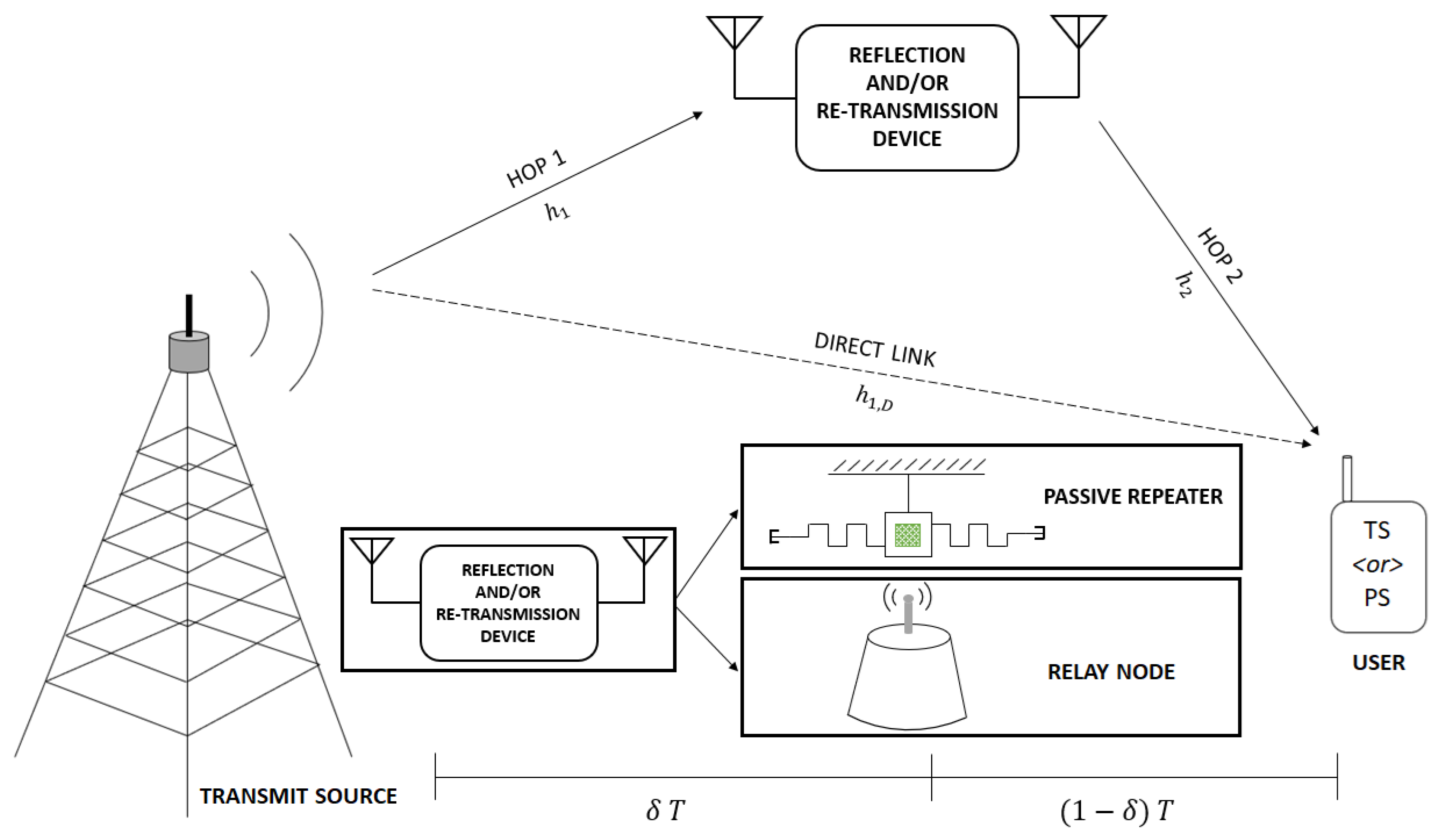
- In contrast to the existing reflector-only and relaying-only techniques, we propose a novel hybrid active-and-passive relaying scheme to facilitate SWIPT to a PS- or TS-enabled end-user, along with the dynamic designing of dual-hop TP, under certain receive processing assumptions.
- (ii)
- We formulate a novel problem (incorporating the three systems) to maximize the weighted utility function comprising data throughput, harvested energy and transmit power, subjected to some quality-of-service (QoS) constraints. Unlike the other works that assume equal time-intervals in the two hops (also considered herein as the benchmarks), we present a framework to dynamically design the TP for the dual-hop link, along with the computation of the PS or TS factors.
- (iii)
- In order to solve the aforementioned problems, we present two distinct methods based on the Lagrange dual technique and Dinkelbach method assisted convex programming, respectively, where both the approaches yield an appreciable solution within polynomial computational-time.
- (iv)
- The effectiveness of the proposed hybrid active-and-passive relaying scheme is shown over the reflector-only and relay-only schemes for both PS and TS SWIPT schemes via numerical analysis, with individual benefits shown over their respective benchmark designs having a fixed TP.
1.5. Further Organization of the Paper
2. System Model
3. Analysis of Greencom Network Scenarios
3.1. Traditional Passive Repeater or Active Relay-Based Systems
3.2. Proposed Hybrid Active-and-Passive Relaying Scheme
4. Problem Formulation and Solution
4.1. Variable Definitions to Assist the Problem Formulation
4.2. Optimization Problem with Weighted Utility Function
4.3. Proposed Solutions to the Above-Mentioned Problem
4.3.1. Method to Seek an Asymptotically Optimal Solution
4.3.2. Dinkelback Method Assisted Convex Programming
| Algorithm 1 Dinkelbach-assisted Alternating Parameter Optimization |
|
5. Numerical Results
5.1. Simulation Set-Up
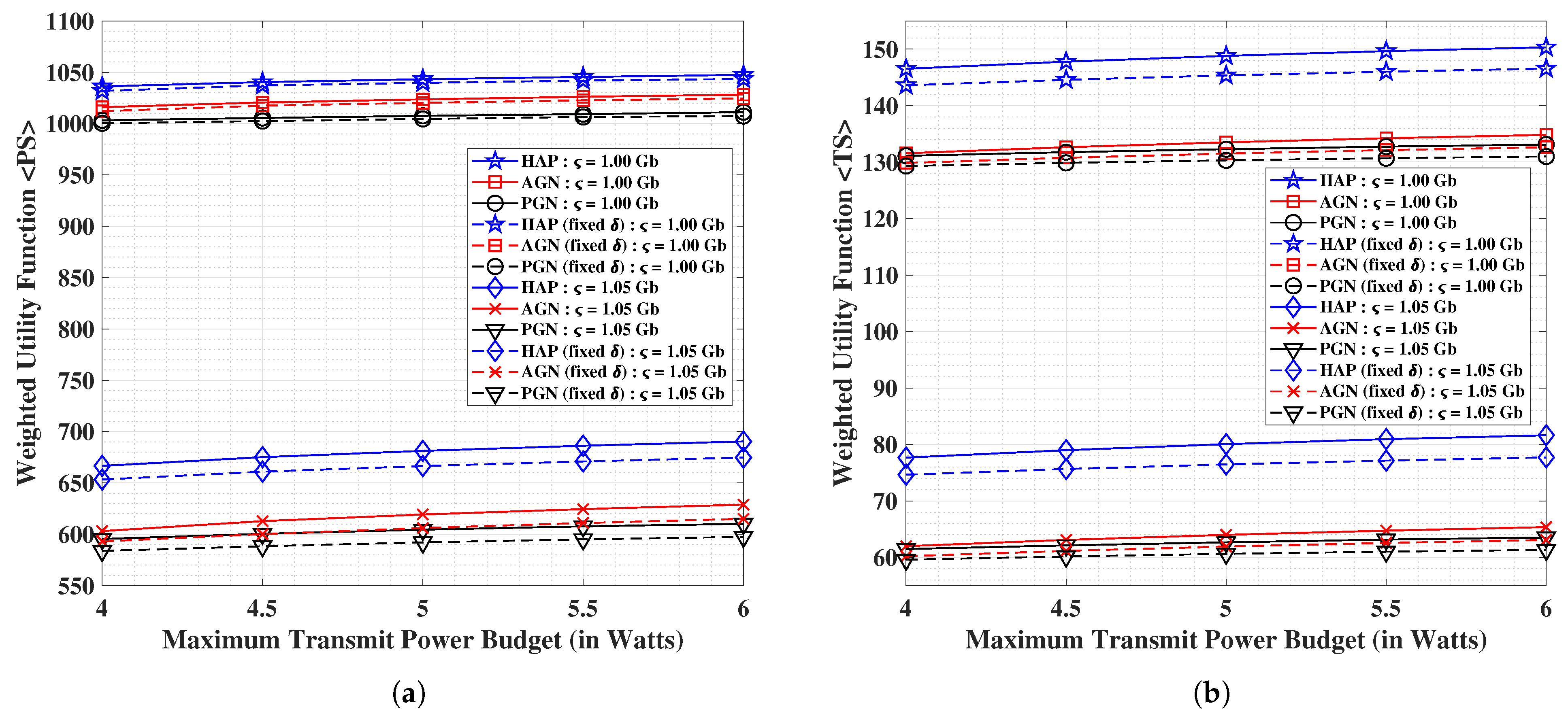
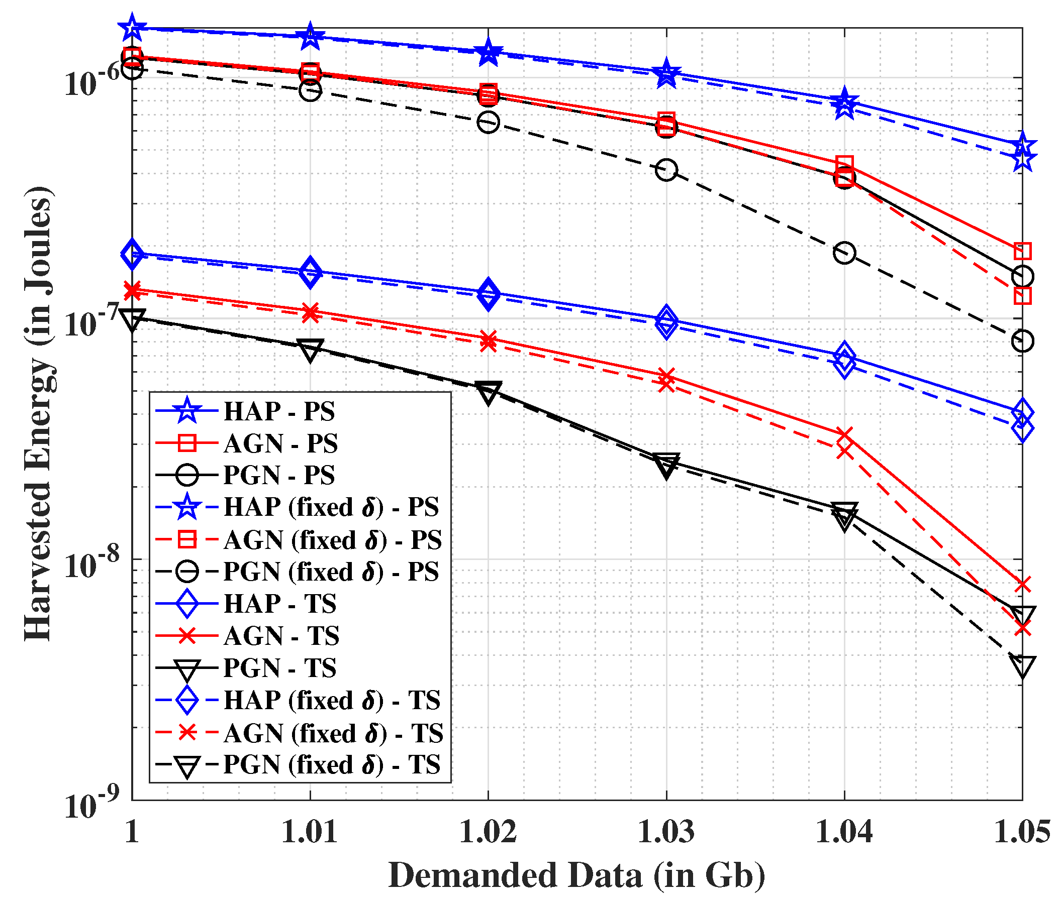
5.2. Experimental Findings and Analysis
5.3. General Outcomes and Trailing Discussion
6. Conclusions
Author Contributions
Funding
Data Availability Statement
Conflicts of Interest
References
- Viswanathan, H.; Mogensen, P.E. Communications in the 6G Era. IEEE Access 2020, 8, 57063–57074. [Google Scholar] [CrossRef]
- Rappaport, T.S.; Xing, Y.; MacCartney, G.R.; Molisch, A.F.; Mellios, E.; Zhang, J. Overview of Millimeter Wave Communications for Fifth-Generation (5G) Wireless Networks-with a Focus on Propagation Models. IEEE Trans. Antennas Propag. 2017, 65, 6213–6230. [Google Scholar] [CrossRef]
- TELCOMA-Global. 5G Technology, Vision, Performance, RAN and Core Network. Telecom Daily Post, 1 August.
- Sharetechnote. 5G/NR - FR/Operating Bandwidth. Available online: sharetechnote.com (accessed on 30 August 2021).
- Haksuki, S. Fixed Wireless Communications at 60 GHz Unique Oxygen Absorption Properties. Available online: rfglobalnet.com (accessed on 30 August 2021).
- Horwitz, J. The Definitive Guide to 5G Low, Mid, and High Band Speeds. VentureBeat Online Magazine, 10 December.
- Davies, D. Small Cells—Big in 5G. Nokia, 20 May.
- Kumbhani, B.; Kshetrimayum, R.S. Source and Relay Transmit Antenna Selection in Two Hop Cooperative Communication Systems Over κ-μ Fading Channels. In Proceedings of the 2016 Twenty Second National Conference on Communication (NCC), Guwahati India, 4–6 March 2016; pp. 1–5. [Google Scholar] [CrossRef]
- Arti, M.K.; Bhatnagar, M.R. Performance Analysis of Hop-by-Hop Beamforming and Combining in DF MIMO Relay System over Nakagami-m Fading Channels. IEEE Commun. Lett. 2013, 17, 2080–2083. [Google Scholar] [CrossRef]
- Gautam, S.; Sharma, S.K.; Chatzinotas, S.; Ottersten, B. Modeling and Optimization of RF-Energy Harvesting-assisted Quantum Battery System. In Proceedings of the 2021 IEEE 93rd Vehicular Technology Conference (VTC2021-Spring), Helsinki, Finland, 25–28 April 2021; pp. 1–6. [Google Scholar] [CrossRef]
- Lumpkins, W. Nikola Tesla’s Dream Realized: Wireless Power Energy Harvesting. IEEE Consum. Electron. Mag. 2014, 3, 39–42. [Google Scholar] [CrossRef]
- Valenta, C.R.; Durgin, G.D. Harvesting Wireless Power: Survey of Energy-Harvester Conversion Efficiency in Far-Field, Wireless Power Transfer Systems. IEEE Microw. Mag. 2014, 15, 108–120. [Google Scholar] [CrossRef]
- Wang, L.; Todaria, P.; Pandey, A.; O’Connor, J.; Chernow, B.; Zuo, L. An Electromagnetic Speed Bump Energy Harvester and its Interactions with Vehicles. IEEE/ASME Trans. Mechatron. 2016, 21, 1985–1994. [Google Scholar] [CrossRef]
- Ruan, T.; Chew, Z.J.; Zhu, M. Energy-Aware Approaches for Energy Harvesting Powered Wireless Sensor Nodes. IEEE Sens. J. 2017, 17, 2165–2173. [Google Scholar] [CrossRef]
- Yang, Z.; Xu, W.; Shikh-Bahaei, M. Energy Efficient UAV Communication with Energy Harvesting. IEEE Trans. Veh. Technol. 2020, 69, 1913–1927. [Google Scholar] [CrossRef] [Green Version]
- Huang, K.; Larsson, E. Simultaneous Information and Power Transfer for Broadband Wireless Systems. IEEE Trans. Signal Process. 2013, 61, 5972–5986. [Google Scholar] [CrossRef] [Green Version]
- Gautam, S.; Ubaidulla, P. Simultaneous Transmission of Information and RF Energy in Multicarrier Systems. In Proceedings of the 2016 23rd International Conference on Telecommunications (ICT), Thessaloniki, Greece, 16–18 May 2016; pp. 1–5. [Google Scholar] [CrossRef]
- Zhou, X.; Zhang, R.; Ho, C.K. Wireless Information and Power Transfer in Multiuser OFDM Systems. IEEE Trans. Wirel. Commun. 2014, 13, 2282–2294. [Google Scholar] [CrossRef] [Green Version]
- Gautam, S.; Ubaidulla, P. Relay Selection and Transceiver Design for Joint Wireless Information and Energy Transfer in Cooperative Networks. In Proceedings of the 2017 IEEE 85th Vehicular Technology Conference (VTC Spring), Sydney, Australia, 4–7 June 2017; pp. 1–5. [Google Scholar] [CrossRef] [Green Version]
- Gautam, S.; Krivochiza, J.; Haqiqatnejad, A.; Chatzinotas, S.; Ottersten, B. Boosting SWIPT via Symbol-Level Precoding. In Proceedings of the 2020 IEEE 21st International Workshop on Signal Processing Advances in Wireless Communications (SPAWC), Atlanta, GA, USA, 26–29 May 2020; pp. 1–5. [Google Scholar] [CrossRef]
- Gautam, S.; Lagunas, E.; Vuppala, S.; Chatzinotas, S.; Ottersten, B. Pricing Perspective for SWIPT in OFDM-based Multi-User Wireless Cooperative Systems. In Proceedings of the 2019 IEEE Wireless Communications and Networking Conference (WCNC), Marrakech, Morocco, 15–18 April 2019; pp. 1–7. [Google Scholar] [CrossRef] [Green Version]
- Boyd, S.; Boyd, S.P.; Vandenberghe, L. Convex Optimization; Cambridge University Press: Cambridge, UK, 2004. [Google Scholar]
- Neos-Guide. Optimization Taxonomy. 2020. Available online: https://neos-guide.org/content/optimization-taxonomy (accessed on 30 August 2021).
- Gautam, S.; Lagunas, E.; Kisseleff, S.; Chatzinotas, S.; Ottersten, B. Successive Convex Approximation for Transmit Power Minimization in SWIPT-Multicast Systems. In Proceedings of the ICC 2020—2020 IEEE International Conference on Communications (ICC), Dublin, Ireland, 7–11 June 2020; pp. 1–7. [Google Scholar] [CrossRef]
- Gautam, S.; Lagunas, E.; Chatzinotas, S.; Ottersten, B. Feasible Point Pursuit and Successive Convex Approximation for Transmit Power Minimization in SWIPT-Multigroup Multicasting Systems. IEEE Trans. Green Commun. Netw. 2021, 5, 884–894. [Google Scholar] [CrossRef]
- Gautam, S.; Lagunas, E.; Chatzinotas, S.; Ottersten, B. Wireless Multi-group Multicast Precoding with Selective RF Energy Harvesting. In Proceedings of the 2019 27th European Signal Processing Conference (EUSIPCO), A Coruña, Spain, 2–6 September 2019; pp. 1–5. [Google Scholar] [CrossRef] [Green Version]
- Gautam, S.; Lagunas, E.; Chatzinotas, S.; Ottersten, B. Relay Selection and Resource Allocation for SWIPT in Multi-User OFDMA Systems. IEEE Trans. Wirel. Commun. 2019, 18, 2493–2508. [Google Scholar] [CrossRef]
- Shen, K.; Yu, W. Fractional Programming for Communication Systems—Part I: Power Control and Beamforming. IEEE Trans. Signal Process. 2018, 66, 2616–2630. [Google Scholar] [CrossRef] [Green Version]
- Gautam, S.; Chatzinotas, S.; Ottersten, B. Energy Efficiency Optimization Technique for SWIPT-Enabled Multi-Group Multicasting Systems with Heterogeneous Users. In Proceedings of the ICASSP 2021—2021 IEEE International Conference on Acoustics, Speech and Signal Processing (ICASSP), Toronto, ON, Canada, 6–11 June 2021; pp. 4880–4884. [Google Scholar] [CrossRef]
- Yang, G.; Zhang, Q.; Liang, Y.C. Cooperative Ambient Backscatter Communications for Green Internet-of-Things. IEEE Internet Things J. 2018, 5, 1116–1130. [Google Scholar] [CrossRef] [Green Version]
- Hiranandani, S.; Mohadikar, S.; Khawaja, W.; Ozdemir, O.; Guvenc, I.; Matolak, D. Effect of Passive Reflectors on the Coverage of IEEE 802.11ad mmWave Systems. In Proceedings of the 2018 IEEE 88th Vehicular Technology Conference (VTC-Fall), Chicago, IL, USA, 27–30 August 2018; pp. 1–6. [Google Scholar] [CrossRef]
- Gautam, S.; Lagunas, E.; Chatzinotas, S.; Ottersten, B. Sequential Resource Distribution Technique for Multi-User OFDM-SWIPT Based Cooperative Networks. In Proceedings of the 2018 IEEE Global Communications Conference (GLOBECOM), Abu Dhabi, United Arab Emirates, 9–13 December 2018; pp. 1–7. [Google Scholar] [CrossRef] [Green Version]
- Gautam, S.; Lagunas, E.; Sharma, S.K.; Chatzinotas, S.; Ottersten, B. Relay Selection Strategies for SWIPT-Enabled Cooperative Wireless Systems. In Proceedings of the 2017 IEEE 28th Annual International Symposium on Personal, Indoor, and Mobile Radio Communications (PIMRC), Montreal, QC, Canada, 8–13 October 2017; pp. 1–7. [Google Scholar] [CrossRef] [Green Version]
- Zhou, X.; Zhang, R.; Ho, C.K. Wireless Information and Power Transfer: Architecture Design and Rate-Energy Tradeoff. IEEE Trans. Commun. 2013, 61, 4754–4767. [Google Scholar] [CrossRef] [Green Version]
- Andrawes, A.; Nordin, R.; Abdullah, N.F. Energy-Efficient Downlink for Non-Orthogonal Multiple Access with SWIPT under Constrained Throughput. Energies 2019, 13, 107. [Google Scholar] [CrossRef] [Green Version]
- Singh, U.; Solanki, S.; Gurjar, D.S.; Upadhyay, P.K.; da Costa, D.B. Wireless Power Transfer in Two-Way AF Relaying with Maximal-Ratio Combining under Nakagami-m Fading. In Proceedings of the 2018 14th International Wireless Communications Mobile Computing Conference (IWCMC), Limassol, Cyprus, 25–29 June 2018; pp. 169–173. [Google Scholar] [CrossRef]
- Solanki, S.; Upadhyay, P.K.; Da Costa, D.B.; Ding, H.; Moualeu, J.M. Performance Analysis of Piece-Wise Linear Model of Energy Harvesting-Based Multiuser Overlay Spectrum Sharing Networks. IEEE Open J. Commun. Soc. 2020, 1, 1820–1836. [Google Scholar] [CrossRef]
- Liaskos, C.; Nie, S.; Tsioliaridou, A.; Pitsillides, A.; Ioannidis, S.; Akyildiz, I. A New Wireless Communication Paradigm through Software-Controlled Metasurfaces. IEEE Commun. Mag. 2018, 56, 162–169. [Google Scholar] [CrossRef] [Green Version]
- Di Renzo, M.; Zappone, A.; Debbah, M.; Alouini, M.S.; Yuen, C.; de Rosny, J.; Tretyakov, S. Smart Radio Environments Empowered by Reconfigurable Intelligent Surfaces: How It Works, State of Research, and The Road Ahead. IEEE J. Sel. Areas Commun. 2020, 38, 2450–2525. [Google Scholar] [CrossRef]
- Björnson, E.; Özdogan, O.; Larsson, E.G. Reconfigurable Intelligent Surfaces: Three Myths and Two Critical Questions. IEEE Commun. Mag. 2020, 58, 90–96. [Google Scholar] [CrossRef]
- Wu, Q.; Zhang, S.; Zheng, B.; You, C.; Zhang, R. Intelligent Reflecting Surface-Aided Wireless Communications: A Tutorial. IEEE Trans. Commun. 2021, 69, 3313–3351. [Google Scholar] [CrossRef]
- Huang, C.; Zappone, A.; Alexandropoulos, G.C.; Debbah, M.; Yuen, C. Reconfigurable Intelligent Surfaces for Energy Efficiency in Wireless Communication. IEEE Trans. Wirel. Commun. 2019, 18, 4157–4170. [Google Scholar] [CrossRef] [Green Version]
- Wu, Q.; Zhang, R. Intelligent Reflecting Surface Enhanced Wireless Network via Joint Active and Passive Beamforming. IEEE Trans. Wirel. Commun. 2019, 18, 5394–5409. [Google Scholar] [CrossRef] [Green Version]
- Pei, X.; Yin, H.; Tan, L.; Cao, L.; Li, Z.; Wang, K.; Zhang, K.; Björnson, E. RIS-Aided Wireless Communications: Prototyping, Adaptive Beamforming, and Indoor/Outdoor Field Trials. arXiv 2021, arXiv:2103.00534. [Google Scholar]
- Björnson, E.; Wymeersch, H.; Matthiesen, B.; Popovski, P.; Sanguinetti, L.; de Carvalho, E. Reconfigurable Intelligent Surfaces: A Signal Processing Perspective with Wireless Applications. arXiv 2021, arXiv:2102.00742. [Google Scholar]
- Cui, T.J.; Liu, S.; Zhang, L. Information Metamaterials and Metasurfaces. J. Mater. Chem. C 2017, 5, 3644–3668. [Google Scholar] [CrossRef]
- Shelby, R.A.; Smith, D.R.; Schultz, S. Experimental Verification of a Negative Index of Refraction. Science 2001, 292, 77–79. [Google Scholar] [CrossRef] [Green Version]
- Liang, Y.C.; Long, R.; Zhang, Q.; Chen, J.; Cheng, H.V.; Guo, H. Large Intelligent Surface/Antennas (LISA): Making Reflective Radios Smart. J. Commun. Inf. Netw. 2019, 4, 40–50. [Google Scholar]
- Tsilipakos, O.; Tasolamprou, A.C.; Pitilakis, A.; Liu, F.; Wang, X.; Mirmoosa, M.S.; Tzarouchis, D.C.; Abadal, S.; Taghvaee, H.; Liaskos, C.; et al. Toward Intelligent Metasurfaces: The Progress from Globally Tunable Metasurfaces to Software-Defined Metasurfaces with an Embedded Network of Controllers. Adv. Opt. Mater. 2020, 8, 2000783. [Google Scholar] [CrossRef]
- Liu, H.; Zhang, J.; Wu, Q.; Jin, Y.; Chen, Y.; Ai, B. RIS-Aided Next-Generation High-Speed Train Communications: Challenges, Solutions, and Future Directions. arXiv 2021, arXiv:2103.09484. [Google Scholar]
- Gautam, S.; Sharma, S.K.; Tran, D.H.; Chatzinotas, S.; Ottersten, B. Hybrid Active-and-Passive Relaying model for SWIPT-enabled 6G-IoT Greencom Networks. Preprints 2020. [Google Scholar] [CrossRef]
- Lyu, B.; Yang, Z.; Guo, H.; Tian, F.; Gui, G. Relay Cooperation Enhanced Backscatter Communication for Internet-of-Things. IEEE Internet Things J. 2019, 6, 2860–2871. [Google Scholar] [CrossRef]
- Rajaram, A.; Khan, R.; Tharranetharan, S.; Jayakody, D.N.K.; Dinis, R.; Panic, S. Novel SWIPT Schemes for 5G Wireless Networks. Sensors 2019, 19, 1169. [Google Scholar] [CrossRef] [PubMed] [Green Version]
- Gong, S.; Huang, X.; Xu, J.; Liu, W.; Wang, P.; Niyato, D. Backscatter Relay Communications Powered by Wireless Energy Beamforming. IEEE Trans. Commun. 2018, 66, 3187–3200. [Google Scholar] [CrossRef]
- Gong, S.; Zou, Y.; Hoang, D.T.; Xu, J.; Cheng, W.; Niyato, D. Capitalizing Backscatter-Aided Hybrid Relay Communications with Wireless Energy Harvesting. IEEE Internet Things J. 2020, 7, 8709–8721. [Google Scholar] [CrossRef]
- Gong, S.; Gao, L.; Xu, J.; Guo, Y.; Hoang, D.T.; Niyato, D. Exploiting Backscatter-Aided Relay Communications with Hybrid Access Model in Device-to-Device Networks. IEEE Trans. Cogn. Commun. Netw. 2019, 5, 835–848. [Google Scholar] [CrossRef]
- Van Huynh, N.; Hoang, D.T.; Lu, X.; Niyato, D.; Wang, P.; Kim, D.I. Ambient Backscatter Communications: A Contemporary Survey. IEEE Commun. Surveys Tuts 2018, 20, 2889–2922. [Google Scholar] [CrossRef] [Green Version]
- Guo, J.; Zhang, H.; Zhu, X. Theoretical Analysis of RF-DC Conversion Efficiency for Class-F Rectifiers. IEEE Trans. Microw. Theory Technol. 2014, 62, 977–985. [Google Scholar] [CrossRef]
- Gautam, S.; Vu, T.X.; Chatzinotas, S.; Ottersten, B. Cache-Aided Simultaneous Wireless Information and Power Transfer (SWIPT) With Relay Selection. IEEE J. Sel. Areas Commun. 2019, 37, 187–201. [Google Scholar] [CrossRef] [Green Version]
- Gautam, S.; Vu, T.X.; Chatzinotas, S.; Ottersten, B. Joint Wireless Information and Energy Transfer in Cache-Assisted Relaying Systems. In Proceedings of the 2018 IEEE Wireless Communications and Networking Conference (WCNC), Barcelona, Spain, 15–18 April 2018; pp. 1–6. [Google Scholar] [CrossRef] [Green Version]
- Kahn, L.R. Ratio squarer. Proc. Inst. Radio Eng. 1954, 42, 1704. [Google Scholar]
- Dinkelbach, W. On Nonlinear Fractional Programming. Manag. Sci. 1967, 13, 492–498. [Google Scholar] [CrossRef]
- Gautam, S.; Lagunas, E.; Sharma, S.K.; Chatzinotas, S.; Ottersten, B.; Vandendorpe, L. Weighted Sum-SINR and Fairness Optimization for SWIPT-Multigroup Multicasting Systems with Heterogeneous Users. IEEE Open J. Commun. Soc. 2020, 1, 1470–1484. [Google Scholar] [CrossRef]
- Gautam, S.; Lagunas, E.; Bandi, A.; Chatzinotas, S.; Sharma, S.K.; Vu, T.X.; Kisseleff, S.; Ottersten, B. Multigroup Multicast Precoding for Energy Optimization in SWIPT Systems with Heterogeneous Users. IEEE Open J. Commun. Soc. 2020, 1, 92–108. [Google Scholar] [CrossRef] [Green Version]
- Shen, X.; Diamond, S.; Gu, Y.; Boyd, S. Disciplined Convex-Concave Programming. In Proceedings of the 2016 IEEE 55th Conference on Decision and Control (CDC), Vegas, NV, USA, 12–14 December 2016; pp. 1009–1014. [Google Scholar]
- Diamond, S.; Boyd, S. CVXPY: A Python-Embedded Modeling Language for Convex Optimization. J. Mach. Learn. Res. 2016, 17, 2909–2913. [Google Scholar]
- MATLAB Optimization Toolbox (Fmincon); 9.7.0.1296695 (R2019b) Update 4; The MathWorks: Natick, MA, USA, 2019.
- Series, P. Propagation Data and Prediction Methods for the Planning of Short-Range Outdoor Radiocommunication Systems and Radio Local Area Networks in the Frequency Range 300 MHz to 100 GHz. Tech. Rep., ITU, Tech. Rep. ITU-R 2017. Available online: https://www.itu.int/dms_pubrec/itu-r/rec/p/R-REC-P.1411-9-201706-S!!PDF-E.pdf (accessed on 4 June 2021).
- Wikipedia. 5G. Available online: https://en.wikipedia.org/wiki/5G (accessed on 30 August 2021).
- Kim, S.H.; Kim, D.I. Hybrid Backscatter Communication for Wireless-Powered Heterogeneous Networks. IEEE Trans. Wirel. Commun. 2017, 16, 6557–6570. [Google Scholar] [CrossRef]
- Mathsisfun. Confidence Interval Calculator. Available online: https://www.mathsisfun.com/data/confidence-interval-calculator.html (accessed on 30 August 2021).
- Mo, Z.; Su, W.; Matyjas, J.D. Amplify and Forward Relaying Protocol Design with Optimum Power and Time Allocation. In Proceedings of the MILCOM 2016—2016 IEEE Military Communications Conference, Baltimore, MD, USA, 1–3 November 2016; pp. 412–417. [Google Scholar] [CrossRef]


| Acronym | Full-Form |
|---|---|
| 3GPP | 3rd Generation Partnership Project |
| 5G | Fifth Generation Mobile Wireless Communications |
| 6G | Sixth Generation Mobile Wireless Communications |
| AF | Amplify-and-Forward |
| AGN | Active Relay Device-based Green Communication Network |
| AR | Active Relay |
| AWGN | Additive White Gaussian Noise |
| CSI | Channel State Information |
| DCCP | Disciplined Convex-Concave Programming |
| DF | Decode-and-Forward |
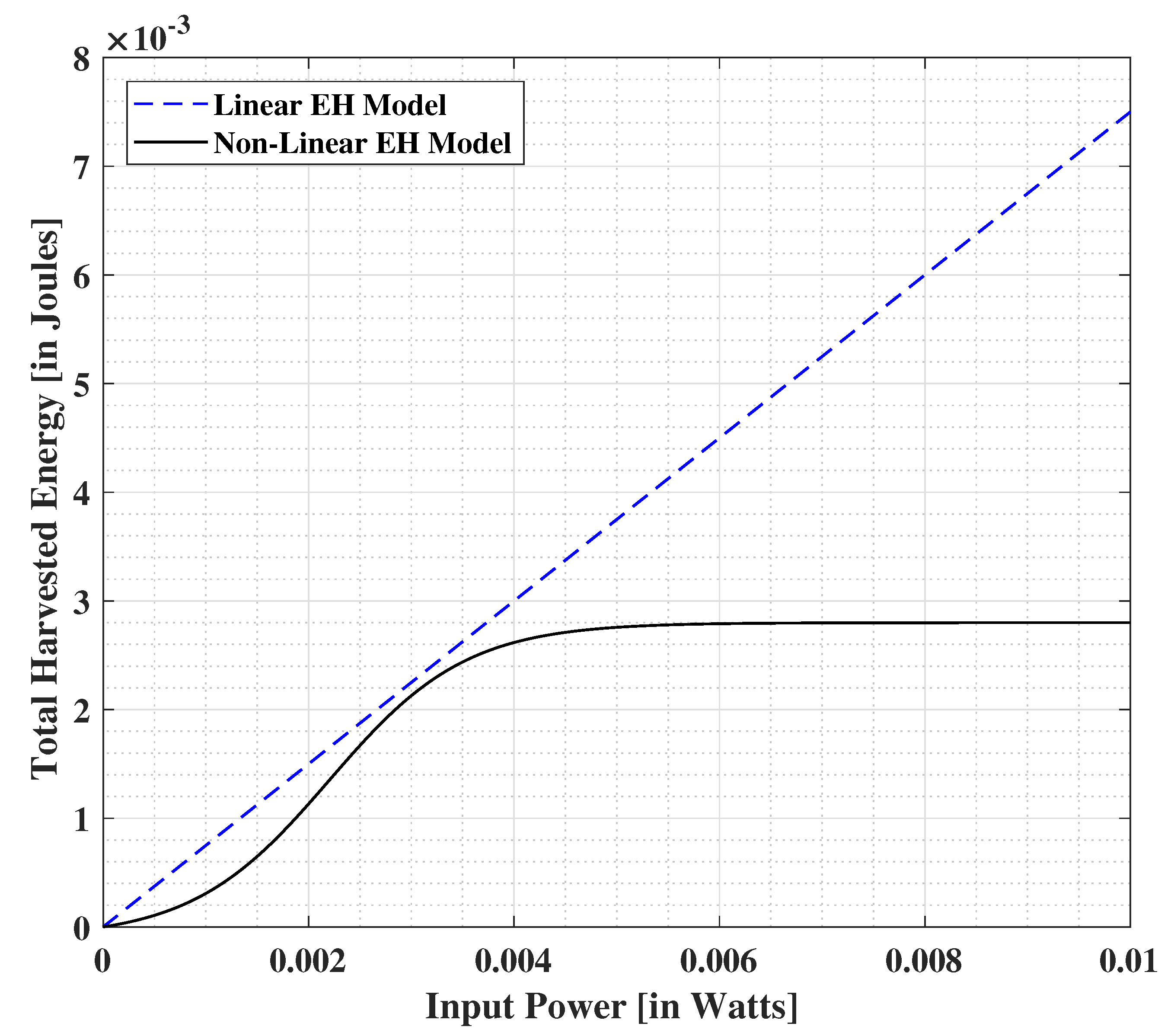
| EH | Energy Harvesting |
| FR1 | Frequency Range-1 for 5G |
| FR2 | Frequency Range-2 for 5G |
| Greencom | Green Communications |
| HAP | Hybrid Active-and-Passive |
| ID | Information Decoding |
| IoT | Internet-of-Things |
| IRS | Intelligent Reflecting Surface |
| KKT | Karush-Kuhn-Tucker |
| MRC | Maximum Ratio Combining |
| NR | New Radio |
| PGN | Passive Repeater Device-based Green Communication Network |
| PR | Passive Repeater |
| PS | Power Splitting |
| QoS | Quality-of-Service |
| RIS | Reconfigurable Intelligent Surface |
| SNR | Signal-to-Noise-Ratio |
| SWIPT | Simultaneous Wireless Information and Power Transfer |
| TP | Time Period |
| TS | Time Switching |
| TSF | Time-Splitting Factor |
| Notation | Definition |
|---|---|
| a | Coefficient associated with increase of path loss with distance |
| Overall bandwidth | |
| b | Coefficient associated with the offset value of path-loss |
| c | Coefficient associated with increase of path loss with frequency |
| d | Distance between the transmitting and receiving stations (in meters) |
| Maximum harvested energy obtained on the saturation of the EH circuit | |
| Non-linear EH (sigmoidal) expression with input power x | |
| Non-linear EH expression for PS scheme | |
| Non-linear EH expression for TS scheme | |
| Harvested energy at the end-user with PS scheme in the PGN/AGN scenario | |
| Harvested energy at the end-user with TS scheme in the PGN/AGN scenario | |
| Parameter to refer to or according to the chosen scheme | |
| Overall harvested energy at the end-user with PS scheme in the HAP scenario | |
| Overall harvested energy at the end-user with TS scheme in the HAP scenario | |
| Parameter to refer to or according to the chosen scheme | |
| Expectation value operator | |
| f | Operational frequency of the system |
| Channel coefficient for the direct link between transmit source and end-user | |
| Channel coefficient for the first phase of indirect link pertaining to PR device | |
| Channel coefficient for the first phase of indirect link pertaining to AR device | |
| Parameter to refer to or according to the chosen scheme | |
| Channel coefficient for the second phase of indirect link pertaining to PR device | |
| Channel coefficient for the second phase of indirect link pertaining to AR device | |
| Parameter to refer to or according to the chosen scheme | |
| Lagrange Dual Function | |
| Lagrangian function operator | |
| n | AWGN introduced at the PR device |
| n | AWGN introduced at the AR device |
| Parameter to refer to or according to the chosen scheme | |
| AWGN introduced due to the antenna element of the end-user | |
| The noise introduced by the baseband processing circuit at the end-user | |
| Transmit power at the source | |
| Maximum overall power available at the relay | |
| Overall power limitation for the transmitter-relay system | |
| Data throughput at the end-user with PS scheme in the PGN/AGN scenario | |
| Data throughput at the end-user with TS scheme in the PGN/AGN scenario | |
| Parameter to refer to or according to the chosen scheme | |
| Overall data throughput at the end-user with PS scheme in the HAP scenario | |
| Overall data throughput at the end-user with TS scheme in the HAP scenario | |
| Parameter to refer to or according to the chosen scheme | |
| Data throughput at the end-user with PS scheme via direct link | |
| Data throughput at the end-user with TS scheme via direct link | |
| Parameter to refer to or according to the chosen scheme | |
| Transmit signal seen at the PR device | |
| Transmit signal seen at the AR device | |
| Parameter to refer to or according to the chosen scheme | |
| s | Symbol tranmsitted from the source |
| T | Time period |
| w | Complex amplification coefficient of the AR device |
| Signal received by the end-user via direct link | |
| Signal received by the end-user via PR device over the second phase | |
| Signal received by the end-user via AR device over the second phase | |
| Parameter to refer to or according to the chosen scheme |
| Symbol | Definition |
|---|---|
| Constants corresponding to the capacitor and diode turn-on voltage at EH circuit | |
| Mean corresponding to the confidence interval formula | |
| Time splitting factor corresponding to TP | |
| Threshold limit corresponding to Algorithm 1 | |
| Reflection efficiency coefficient of the PR device | |
| Z-value corresponding to the confidence interval formula | |
| Parameter to compute the intermediary fraction during the Dinkelbach process | |
| Vector corresponding to the Lagrange dual variables: | |
| The number of observations corresponding to the confidence interval formula | |
| Weighing coefficient corresponding to the harvested energy | |
| Weighing coefficient corresponding to the transmit power | |
| Weighing coefficient corresponding to the data throughput | |
| Power splitting ratio | |
| Standard deviation | |
| Noise variance corresponding to | |
| Noise variance corresponding to | |
| Noise variance corresponding to | |
| Noise variance corresponding to | |
| Parameter to refer to or according to the chosen scheme | |
| Time-switching ratio | |
| Metric to represent or interchangeably | |
| SNR obtained at the end-user with PS scheme via direct link | |
| SNR obtained at the end-user with TS scheme via direct link | |
| SNR estimated at the PR via first hop indirect link | |
| SNR estimated at the AR via first hop indirect link | |
| Parameter to refer to or according to the chosen scheme | |
| SNR obtained at the end-user with PS scheme via second hop PR device link | |
| SNR obtained at the end-user with TS scheme via second hop PR device link | |
| SNR obtained at the end-user with PS scheme via second hop AR device link | |
| SNR obtained at the end-user with TS scheme via second hop AR device link | |
| Parameter to refer to or according to the chosen scheme | |
| Parameter to refer to or according to the chosen scheme | |
| Minimum demanded data throughput | |
| Minimum demanded harvested energy | |
| Metric combining reflection/amplification coefficients of PR/AR, respectively |
| Parameter | P | |||||
|---|---|---|---|---|---|---|
| System | ||||||
| PGN | ||||||
| AGN | ||||||
| HAP | ||||||
| Percentage | 80% | 85% | 90% | 95% | 99% | 99.5% | 99.9% |
|---|---|---|---|---|---|---|---|
| Z-value | 1.282 | 1.440 | 1.645 | 1.960 | 2.576 | 2.807 | 3.291 |
Publisher’s Note: MDPI stays neutral with regard to jurisdictional claims in published maps and institutional affiliations. |
© 2021 by the authors. Licensee MDPI, Basel, Switzerland. This article is an open access article distributed under the terms and conditions of the Creative Commons Attribution (CC BY) license (https://creativecommons.org/licenses/by/4.0/).
Share and Cite
Gautam, S.; Solanki, S.; Sharma, S.K.; Chatzinotas, S.; Ottersten, B. Hybrid Active-and-Passive Relaying Model for 6G-IoT Greencom Networks with SWIPT. Sensors 2021, 21, 6013. https://doi.org/10.3390/s21186013
Gautam S, Solanki S, Sharma SK, Chatzinotas S, Ottersten B. Hybrid Active-and-Passive Relaying Model for 6G-IoT Greencom Networks with SWIPT. Sensors. 2021; 21(18):6013. https://doi.org/10.3390/s21186013
Chicago/Turabian StyleGautam, Sumit, Sourabh Solanki, Shree Krishna Sharma, Symeon Chatzinotas, and Björn Ottersten. 2021. "Hybrid Active-and-Passive Relaying Model for 6G-IoT Greencom Networks with SWIPT" Sensors 21, no. 18: 6013. https://doi.org/10.3390/s21186013