
Needs, Requirements and a Concept of a Tool Condition Monitoring System for the Aerospace Industry

 , , and
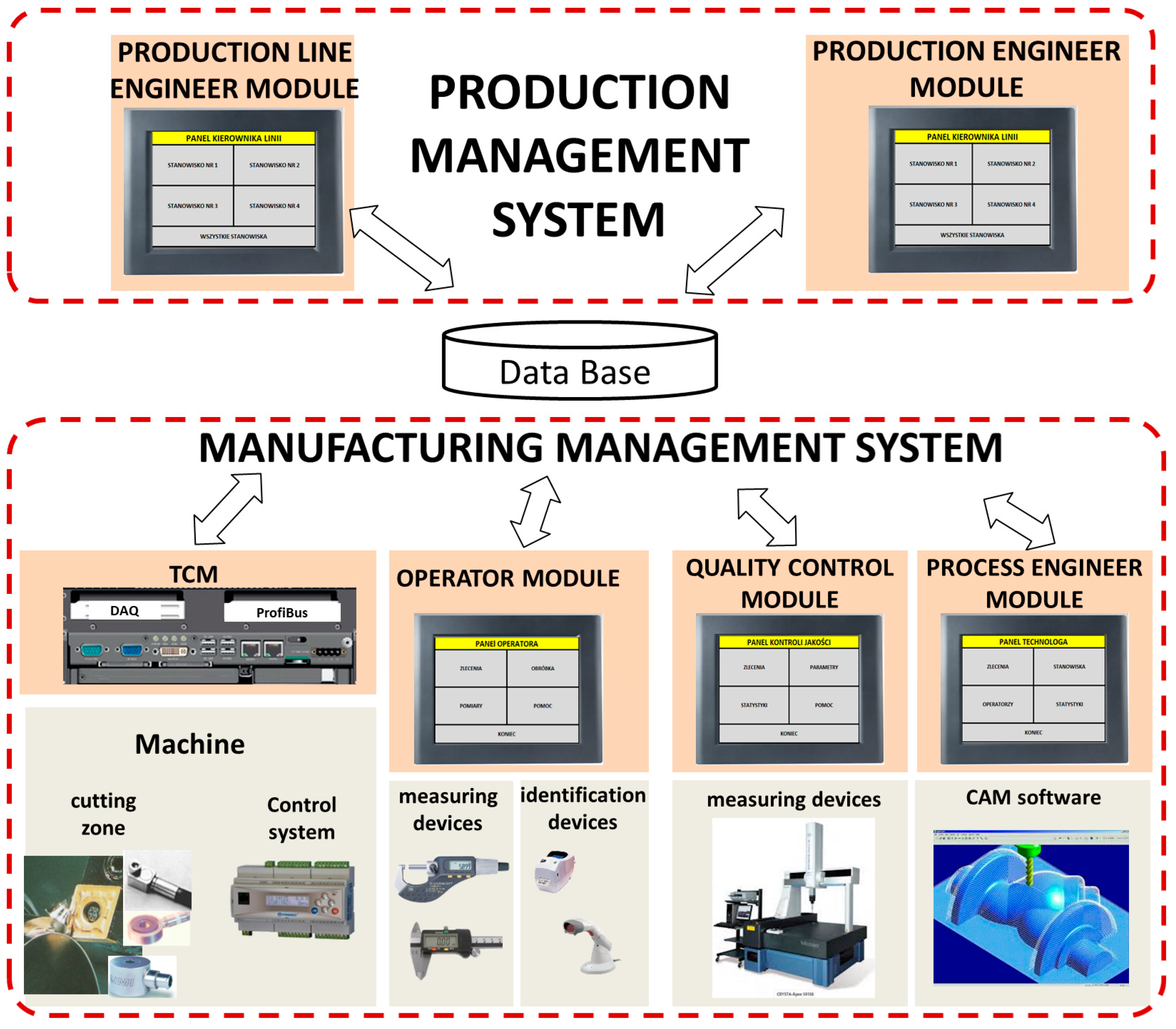
Abstract
:1. Introduction
- Cutting edge wear diagnostics (end of life detection);
- Detection of catastrophic tool failure (CTF);
- Diagnostics of the shapes of metal chips;
- Detection of excessive vibration;
- Others (built-up edge and collision detection).
- Support vector machine (ν-SVM) for prediction of different tool wear states [37];
- Radial basis function-based kernel principal component analysis (KPCA_IRBF) and relevance vector machine (RVM) for a tool flank wear predictive model [38];
- An adaptive time window and deep bidirectional long short-term memory neural network for prediction of the tool failure zone in milling [14];
- A deep learning method based on multiscale feature fusion by parallel convolutional neural networks for tool wear prediction [39];
- An Ellipsoid ARTMAP (EAM) network model based on incremental learning algorithm for recognizing the wear states of milling tool [40];
- An HMM algorithm and multilayer perceptron (MLP) for accelerated wear [41];
- Recurrent neural networks for tool wear in turning [42].
2. The Needs of the Production Supervision System in the Concept of Industry 4.0 in the Aerospace Industry
3. The Concept of an Edge-Computing-Based Production Supervision System in Industry 4.0
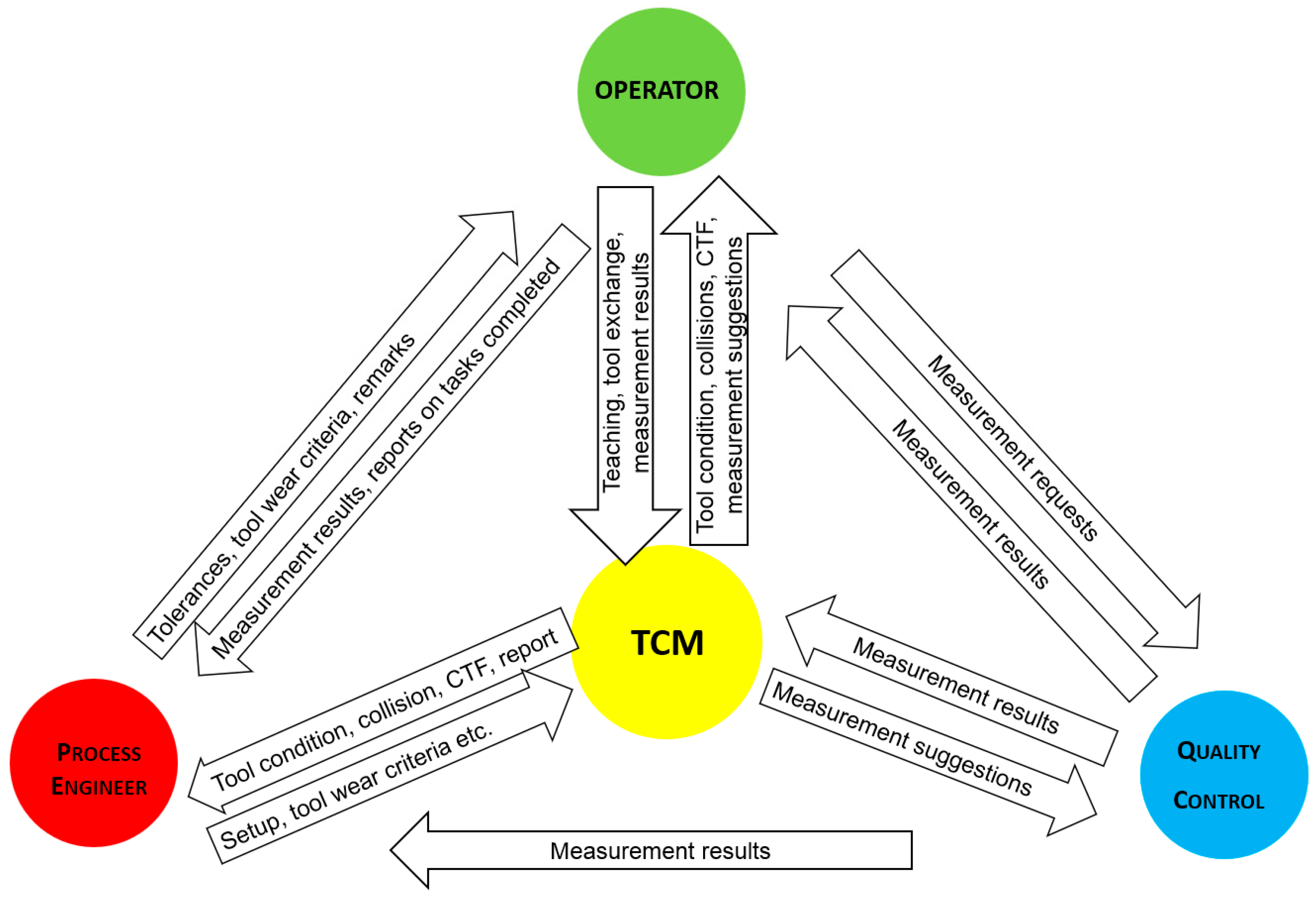
- The process engineer sends information about the diagnostic settings (e.g., sensitivity, selection of tools and sensors to be monitored, machining method declaration, tool definitions, etc.) to the TCM system, and also assigns individual tools to the machined surfaces on the part. On the basis of this information, the TCM system suggests validation of individual surfaces in the case of high cutting edge wear, defines the machining program according to which part is machined, and makes it available to the TCM system.
- The process engineer provides the operator with technological settings (guidelines for performing measurements, permissible deviations of measured parameters, tool wear criteria, and remarks).
- The TCM system transmits to the process engineer diagnostic signals, work progress reports, and results of machining process supervision on a given cell (e.g., date/time of execution of individual operations, operator’s name, tool wear values after execution of individual operations, and information on occurrence of emergency situations (collisions and catastrophic tool failures).
- The TCM system sends, to the operator, information about estimated tool wear, occurrence or threat of emergency situations (collisions and catastrophic tool damage), proposals for tool replacement, and estimated number of operations that can be performed at a given tool edge.
- The TCM operator provides information on tool replacement, and a suitably qualified operator also has the authority to teach the supervision system.
- The operator provides the process engineer with reports on completed tasks (orders and operations), measurement results, and comments.
- Quality control sends the measurement results to the process engineer.
- The TCM system can send suggestions to quality control about measurements at a site, such as when there is high tool wear.
4. Edge-Computing-Based Tool Condition and Cutting Process Module
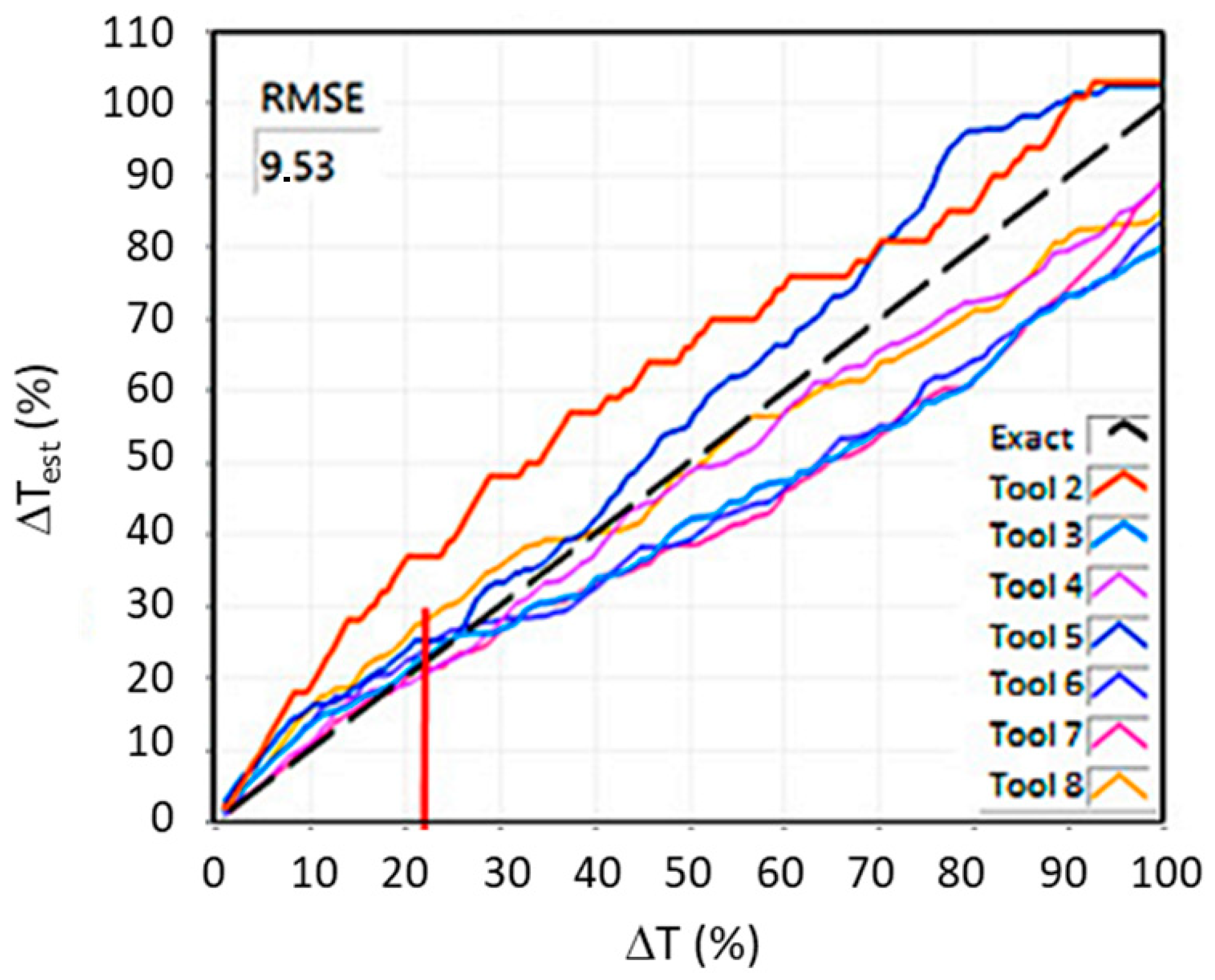
- Estimation of gradual tool wear (GTW). With a small number of operations in the life cycle, tool replacement may be necessary during operation. Thus, the algorithm must make a diagnosis about the state of the tool much more frequently than once per operation. An example of an algorithm that could be used here is the algorithm presented in [47]. Here, the tool wear diagnosis is presented up to 20 times per operation. Figure 4 shows the estimated tool wear using this algorithm for seven tools (from Tool 2 to Tool 8) and an ideal run (Exact). The tool wear rate presented by the system is used, here, as the used tool life ratio ΔT, which is an indicator that has long been used in tool condition diagnostics [48], shown in the figure as ΔTest versus actual ΔT. Currently, the more popular RUL (remaining useful life) ratio is derived from the ΔT ratio according to the formula RUL = 100% − ΔT. The estimation error by the ΔT algorithm is shown as the root mean square error (RMSE). The number of operations per tool life is from seven to ten, and the tool wear estimates are much higher. The solution performs well from about five operations per tool life. Further development of diagnostic algorithms should lead to even lower numbers of operations per tool life, even below one, because such cases also occur in the aerospace industry.
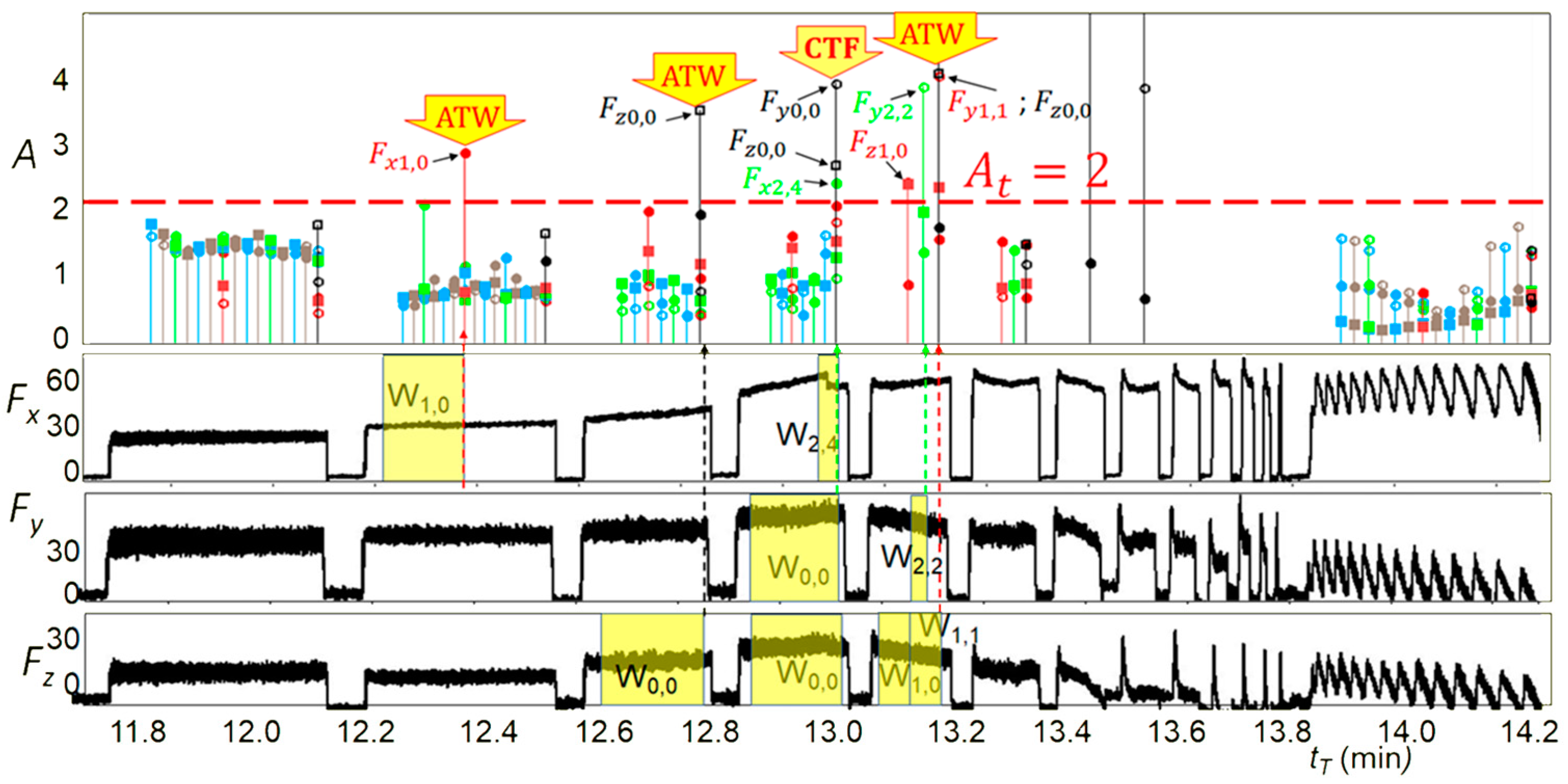
- Detection of accelerated tool wear. Accelerated tool wear (ATW) often precedes the occurrence of catastrophic tool failure (CTF) and detecting it could prevent CTF. The ATW phenomenon is much more dynamic than GTW, therefore, the diagnosis is made much more frequently, at most within a few seconds and the faster the better, for example, the algorithm proposed in [49] can be used here. This algorithm detects accelerated natural wear and very small chipping (ATW) as well as larger chipping and tool breakage (CTF). The diagnosis is made every second. The results of this algorithm are shown in Figure 5. It shows the waveform of the signal shape change rate A in windows of different length Wi, j, where i is the number of passes and j is the number of windows in a pass. It also shows the courses of cutting forces Fx, Fy, and Fz on which diagnostics were performed. In addition, it indicates whether exceeding the threshold A = 2 triggering the alarm was caused by ATW or CTF. This algorithm can work even if there is less than one operation per tool life, but several operations must be used for learning anyway. Further development of this type of algorithm should lead to algorithms that do not require learning.
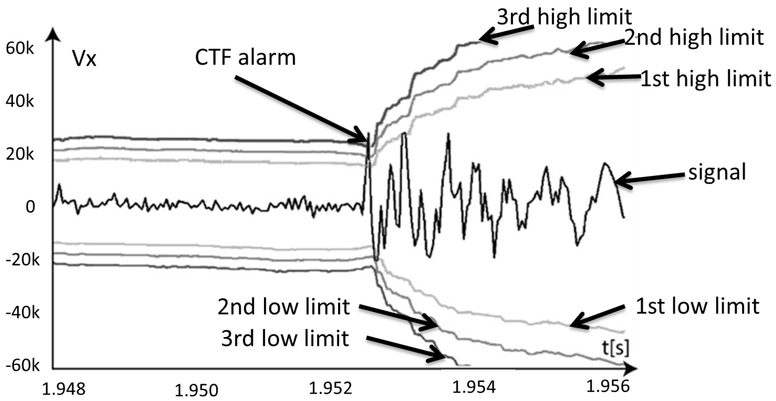
- Detection of catastrophic tool failure. The CTF must be detected in a fraction of a second, otherwise the workpiece may be damaged. The shorter the response time of the system, the lower the probability of this failure. For example, the algorithm developed in [50] can be used here. This algorithm can work based on force and/or vibration sensor signals. The latter is only effective with stable processing. Figure 6 shows how an algorithm like this works with the example of a vibration sensor signal. The waveform of the signal, the dynamic limits determined from the current dynamic component, and the additional coefficient obtained by the learning process are shown. The training can be performed on life periods of arbitrarily small number of operations. The CTF alarm is reported, here, less than 0.04 s after its occurrence. Further development of these algorithms should focus on eliminating the need to learn the system while being resistant to signal disturbances caused by changes in the cross-section of the machined layer or other reasons.
- Detection of cutting, i.e., the system automatically recognizes cutting and separates cutting periods into signals from fast feeds, as well as run-up and run-down;
- Automatic selection of signal segments with a fixed waveform [51];
- Determination of hundreds of signal features from the selected signal segments;
- Automatic selection of useful features (correlated with the tool condition) and elimination similar features (correlated with each other) for each individual segment [52];
- Determination of the used part of tool life for each feature separately and integration of indications into one evaluation, displayed to an operator as a percentage of tool wear.
- The name of the machining program;
- Two-state information on the status of operations, i.e., the start and end of the machining program and the start-stop of the working feed with division into individual axes;
- Information about the values of feed rates in individual axes, rotational and cutting speed, the number of the currently executed block, identification of the currently working tool (at least the number of the tool socket, and preferably the full name of the machining tool);
- The control system should have eight digital line outputs that transmit information about special functions from the level of the program executed by the machine tool;
- The control system should have two digital inputs, i.e., one to stop the feed rate and retract from the contour of the workpiece, and one to operate a special function in the machine tool program to wait for a “high” signal to appear at the digital input.
5. Summary
Author Contributions
Funding
Institutional Review Board Statement
Informed Consent Statement
Data Availability Statement
Acknowledgments
Conflicts of Interest
References
- Stock, T.; Seliger, G. Opportunities of sustainable manufacturing in industry 4.0. Procedia CIRP 2016, 40, 536–541. [Google Scholar] [CrossRef] [Green Version]
- Lee, J.; Bagheri, B.; Kao, H. A cyber-physical systems architecture for industry 4.0-based manufacturing systems. Manuf. Lett. 2015, 3, 18–23. [Google Scholar] [CrossRef]
- Villalonga, A.; Beruvides, G.; Castano, F.; Haber, R.E. Cloud-Based Industrial Cyber-Physical System for Data-Driven Reasoning: A Review and Use Case on an Industry 4.0 Pilot Line. IEEE Trans. Ind. Inform. 2020, 16, 5975–5984. [Google Scholar] [CrossRef]
- Seferagić, A.; Famaey, J.; De Poorter, E.; Hoebeke, J. Survey on Wireless Technology Trade-Offs for the Industrial Internet of Things. Sensors 2020, 20, 488. [Google Scholar] [CrossRef] [Green Version]
- Castaño, F.; Strzelczak, S.; Villalonga, A.; Haber, R.E.; Kossakowska, J. Sensor reliability in cyber-physical systems using internet-of-things data: A review and case study. Remote Sens. 2019, 11, 2252. [Google Scholar] [CrossRef] [Green Version]
- Jemielniak, K. Commercial tool condition monitoring systems. Int. J. Adv. Manuf. Technol. 1999, 15, 711–721. [Google Scholar] [CrossRef]
- Montronix. Available online: https://www.montronix.com/en/ (accessed on 12 April 2021).
- Nordmann. Available online: https://www.toolmonitoring.com/ (accessed on 12 April 2021).
- Artis Marposs. Available online: https://artis.de/eng/ (accessed on 12 April 2021).
- DigitalWay. Available online: https://www.digitalway.fr/ (accessed on 12 April 2021).
- Jemielniak, K. Contemporary challenges in tool condition monitoring. J. Mach. Eng. 2019, 19, 48–61. [Google Scholar] [CrossRef]
- Caggiano, A.; Segreto, T.; Teti, R. Cloud Manufacturing Framework for Smart Monitoring of Machining. Procedia CIRP 2016, 55, 248–253. [Google Scholar] [CrossRef]
- Alique, A.; Haber, R.E.; Ros, S.; Gonzalez, C. Neural network-based model for the prediction of cutting force in milling process. A progress study on a real case. In Proceedings of the 2000 IEEE International Symposium on Intelligent Control. Held Jointly with the 8th IEEE Mediterranean Conference on Control and Automation (Cat. No.00CH37147), Patras, Greece, 19 July 2000; pp. 121–125. [Google Scholar]
- Yuan, J.; Liu, L.; Yang, Z.; Zhang, Y. Tool Wear Condition Monitoring by Combining Variational Mode Decomposition and Ensemble Learning. Sensors 2020, 20, 6113. [Google Scholar] [CrossRef] [PubMed]
- Jemielniak, K.; Urbański, T.; Kossakowska, J.; Bombiński, S. Tool condition monitoring based on numerous signal features. Int. J. Adv. Manuf. Technol. 2012, 59, 73–81. [Google Scholar] [CrossRef] [Green Version]
- Haber, R.E.; Beruvides, G.; Quiza, R.; Hernandez, A. A simple multi-objective optimization based on the cross-entropy method. IEEE Access 2017, 5. [Google Scholar] [CrossRef]
- Teti, R.; Jemielniak, K.; O’Donnell, G.; Dornfeld, D. Advanced monitoring of machining operations. CIRP Ann. Manuf. Technol. 2010, 59, 717–739. [Google Scholar] [CrossRef] [Green Version]
- Jemielniak, K.; Otman, O. Catastrophic Tool Failure Detection Based on AE Signal Analysis. Ann. CIRP 1998, 47, 31–34. [Google Scholar] [CrossRef]
- Li, N.; Chen, Y.; Kong, D.; Tan, S. Force–based tool condition monitoring for turning process using–support vector regression. Int. J. Adv. Manuf. Technol. 2017, 91, 351–361. [Google Scholar] [CrossRef]
- Xie, Z.; Li, J.; Lu, Y. Feature selection and a method to improve the performance of tool condition monitoring. Int. J. Adv. Manuf. Technol. Vol. 2019, 100, 3197–3206. [Google Scholar] [CrossRef]
- Kuntoğlu, M.; Aslan, A.; Sağlam, H.; Pimenov, D.Y.; Giasin, K.; Mikolajczyk, T. Optimization and analysis of surface roughness, flank wear and 5 different sensorial data via tool condition monitoring system in turning of AISI 5140. Sensors 2020, 20, 4377. [Google Scholar] [CrossRef]
- Dong, J.; Subrahmanyam, K.V.R.; San Wong, Y.; Hong, G.S.; Mohanty, A.R. Bayesian–inference–based neural networks for tool wear estimation. Int. J. Adv. Manuf. Technol. 2006, 30, 797–807. [Google Scholar] [CrossRef]
- Sick, B. On-line and indirect tool wear monitoring in turning with artificial neural networks: A review of more than a decade of research. Mech. Syst. Signal Process. 2002, 16, 487–546. [Google Scholar] [CrossRef]
- Scheffer, C.; Heyns, P.C. An industrial tool wear monitoring system for interrupted turning. Mech. Syst. Signal Process. 2004, 18, 1219–1242. [Google Scholar] [CrossRef]
- Zhou, Y.; Xue, W. Review of tool condition monitoring methods in milling processes. Int. J. Adv. Manuf. Technol. 2018, 96, 2509–2523. [Google Scholar] [CrossRef]
- Jemielniak, K.; Kossakowska, J.; Urbański, T. Application of wavelet transform of acoustic emission and cutting force signals for tool condition, monitoring in rough turning of Inconel 625. Proc. IMechE Part B J. Eng. Manuf. 2011, 225, 123–129. [Google Scholar] [CrossRef]
- Zamudio-Ramirez, I.; Antonino-Daviu, J.A.; Trejo-Hernandez, M.; Osornio-Rios, R.A.A. Cutting Tool Wear Monitoring in CNC Machines Based in Spindle-Motor Stray Flux. Signals IEEE Trans. Ind. Inform. 2020. [Google Scholar] [CrossRef]
- Huang, N.; Samuel, S. Hilbert-Huang Transform and Its Application; World Scientific Publishing: Singapore, 2005. [Google Scholar]
- Shen, B.; Gui, Y.; Chen, B.; Lin, Z.; Liu, Q.; Liu, Q. Application of spindle power signals in tool condition monitoring based on HHT algorithm. Int. J. Adv. Manuf. Technol. 2020, 106, 1385–1395. [Google Scholar] [CrossRef]
- Shi, D.; Gindy, N.N. Tool wear predictive model based on least squares support vector machines. Mech. Syst. Signal Process. 2007, 21, 1799–1814. [Google Scholar] [CrossRef]
- Caggiano, A. Tool wear prediction in Ti-6Al-4V machining through multiple sensor monitoring and PCA features pattern recognition. Sensors 2018, 18, 823. [Google Scholar] [CrossRef] [Green Version]
- Yang, Y.; Hao, B.; Hao, X.; Li, L.; Chen, N.; Xu, T.; He, N. A Novel Tool (Single-Flute) Condition Monitoring Method for End Milling Process Based on Intelligent Processing of Milling Force Data by Machine Learning Algorithms. Int. J. Precis. Eng. Manuf. 2020, 21, 2159–2171. [Google Scholar] [CrossRef]
- Salgado, D.R.; Alonso, F.J. Tool wear detection in turning operations using singular spectrum analysis. J. Mater. Process. Technol. 2006, 171, 451–458. [Google Scholar] [CrossRef]
- Li, X.; Ouyang, G.; Liang, Z. Complexity measure of motor current signals for tool flute breakage detection in end milling. Int. J. Mach. Tools Manufact. 2008, 48, 371–379. [Google Scholar] [CrossRef]
- Caggiano, A.; Rimpault, X.; Teti, R.; Balaziński, M.; Chatelain, J.F.; Nele, L. Machine learning approach based on fractal analysis for optimal tool life exploitation in CFRP composite drilling for aeronautical assembly. CIRP Ann. Manuf. Technol. 2018, 67, 483–486. [Google Scholar] [CrossRef]
- Zhang, X.; Zheng, G.; Cheng, X.; Li, Y.; Li, L.; Liu, H. 2D fractal analysis of the cutting force and surface profile in turning of iron-based superalloy. Measurement 2020, 151, 107125. [Google Scholar] [CrossRef]
- Hu, M.; Ming, W.; An, Q.; Chen, M. Tool wear monitoring in milling of titanium alloy Ti–6Al–4 V under MQL conditions based on a new tool wear categorization method. Int. J. Adv. Manuf. Technol. 2019, 104, 4117–4128. [Google Scholar] [CrossRef]
- Kong, D.; Chen, Y.; Li, N.; Duan, C.; Lu, L.; Chen, D. Relevance vector machine for tool wear prediction. Mech. Syst. Signal Process. 2019, 127, 573–594. [Google Scholar] [CrossRef]
- Xu, X.; Wang, J.; Zhong, B.; Ming, W.; Chen, M. Deep learning-based tool wear prediction and its application for machining process using multi-scale feature fusion and channel attention mechanism. Measurement 2021, 177, 109254. [Google Scholar] [CrossRef]
- Liu, C.; Wang, G.F.; Li, Z.M. Incremental learning for online tool condition monitoring using Ellipsoid ARTMAP network model. Appl. Soft Comput. 2015, 35, 186–198. [Google Scholar] [CrossRef]
- Li, W.; Liu, T. Time varying and condition adaptive hidden Markov model for tool wear state estimation and remaining useful life prediction in micro-milling. Mech. Syst. Signal Process. 2019, 131, 689–702. [Google Scholar] [CrossRef]
- Silva, R.; Araújo, A. A Novel Approach to Condition Monitoring of the Cutting Process Using Recurrent Neural Networks. Sensors 2020, 20, 4493. [Google Scholar] [CrossRef]
- Kuntoğlu, M.; Aslan, A.; Pimenov, D.Y.; Usca, Ü.A.; Salur, E.; Gupta, M.K.; Mikolajczyk, T.; Giasin, K.; Kapłonek, W.; Sharma, S. A Review of Indirect Tool Condition Monitoring Systems and Decision-Making Methods in Turning: Critical Analysis and Trends. Sensors 2021, 21, 108. [Google Scholar] [CrossRef]
- Zhang, T.; Li, Y.; Chen, P. Edge computing and its role in Industrial Internet: Methodologies, applications, and future directions. Inf. Sci. 2021, 557, 34–65. [Google Scholar] [CrossRef]
- Modern Material Technologies in Aerospace Industry, WP2. Modelling, Construction and Control of the HSM Process Taking Into Consideration the Configured Machine-Instrument-Detail System, POIG.01.01.02-00-015/08-00, 1 July 2008–31 December 2015. Available online: http://aeronet.pl/projekt_kluczowy.html (accessed on 10 June 2021). (In Polish).
- Advanced Techniques of Aircraft Transmission manufacturing, Program Innowacyjne Lotnictwo, nr INNOLOT/1/10/NCBR/2014, 11 March 2014–30 June 2017. Available online: https://iim.polsl.pl/badania/details/108 (accessed on 10 June 2021). (In Polish).
- Kossakowska, J.; Bombiński, S.; Jemielniak, K. Układ nadzoru stanu narzędzia ADONIS 10. Mechanik 2015, 12, 25–28. [Google Scholar] [CrossRef] [Green Version]
- Bombiński, S.; Jemielniak, K. Hierarchical strategies in tool wear monitoring. In Proceedings of the IIIrd International Conference on Advances in Production Engineering, APE, Warsaw, Poland, 17–19 June 2004; pp. 279–286. [Google Scholar]
- Bombiński, S.; Kossakowska, J.; Jemielniak, K. Detection of accelerated tool wear in turning. Mech. Syst. Signal Process. 2022, 162. [Google Scholar] [CrossRef]
- Bombiński, S. Algorytmy Diagnostyki Stanu Ostrza; Wydawnictwo UTH Radom: Radom, Poland, 2020; Monografie 246; ISBN 978-83-7351-896-4. [Google Scholar]
- Bombiński, S.; Błażejak, K.; Nejman, M.; Jemielniak, K. Sensor signal segmentation for tool condition monitoring. Procedia CIRP 2016, 46, 155–160. [Google Scholar] [CrossRef] [Green Version]
- Jemielniak, K.; Urbański, T.; Kossakowska, J.; Bombiński, S. Multi-feature fusion based tool condition monitoring in rough turning of Inconel 625. Proceedings of 4th CIRP International Conference on High Performance Cutting 2010, Gifu, Japan, 24–26 October 2010; Volume 1, pp. 285–290. [Google Scholar] [CrossRef] [Green Version]


Publisher’s Note: MDPI stays neutral with regard to jurisdictional claims in published maps and institutional affiliations. |
© 2021 by the authors. Licensee MDPI, Basel, Switzerland. This article is an open access article distributed under the terms and conditions of the Creative Commons Attribution (CC BY) license (https://creativecommons.org/licenses/by/4.0/).
Share and Cite
Bombiński, S.; Kossakowska, J.; Nejman, M.; Haber, R.E.; Castaño, F.; Fularski, R. Needs, Requirements and a Concept of a Tool Condition Monitoring System for the Aerospace Industry. Sensors 2021, 21, 5086. https://doi.org/10.3390/s21155086
Bombiński S, Kossakowska J, Nejman M, Haber RE, Castaño F, Fularski R. Needs, Requirements and a Concept of a Tool Condition Monitoring System for the Aerospace Industry. Sensors. 2021; 21(15):5086. https://doi.org/10.3390/s21155086
Chicago/Turabian StyleBombiński, Sebastian, Joanna Kossakowska, Mirosław Nejman, Rodolfo E. Haber, Fernando Castaño, and Robert Fularski. 2021. "Needs, Requirements and a Concept of a Tool Condition Monitoring System for the Aerospace Industry" Sensors 21, no. 15: 5086. https://doi.org/10.3390/s21155086