
Evaluation of Misalignment Effect in Vehicle-to-Vehicle Visible Light Communications: Experimental Demonstration of a 75 Meters Link

 ,
,
Abstract
:1. Introduction
1.1. Visible Light Communications-Related Aspects
1.2. Elements of Novelty in This Article
2. Vehicular Visible Light Communications and Related Work
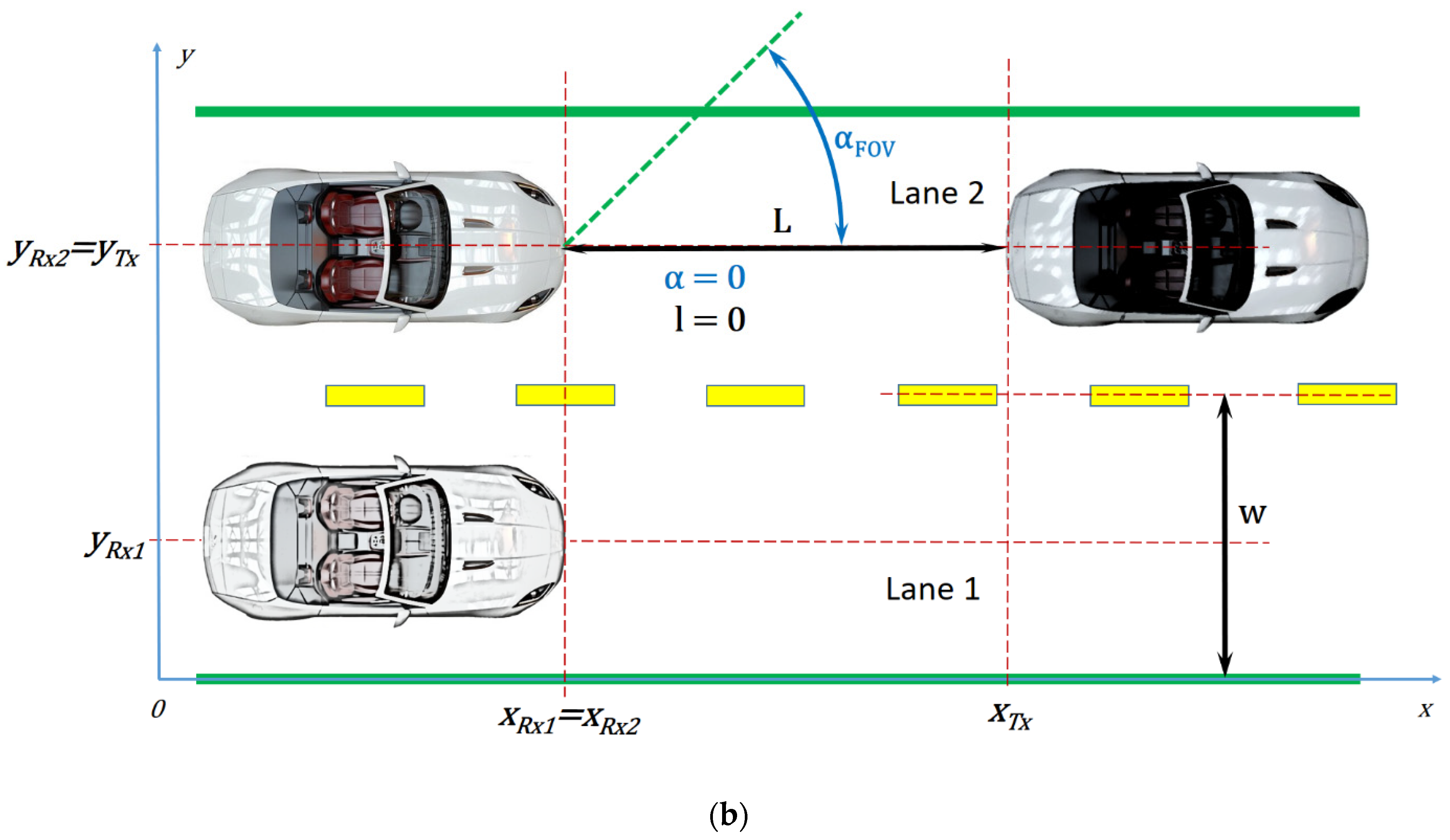
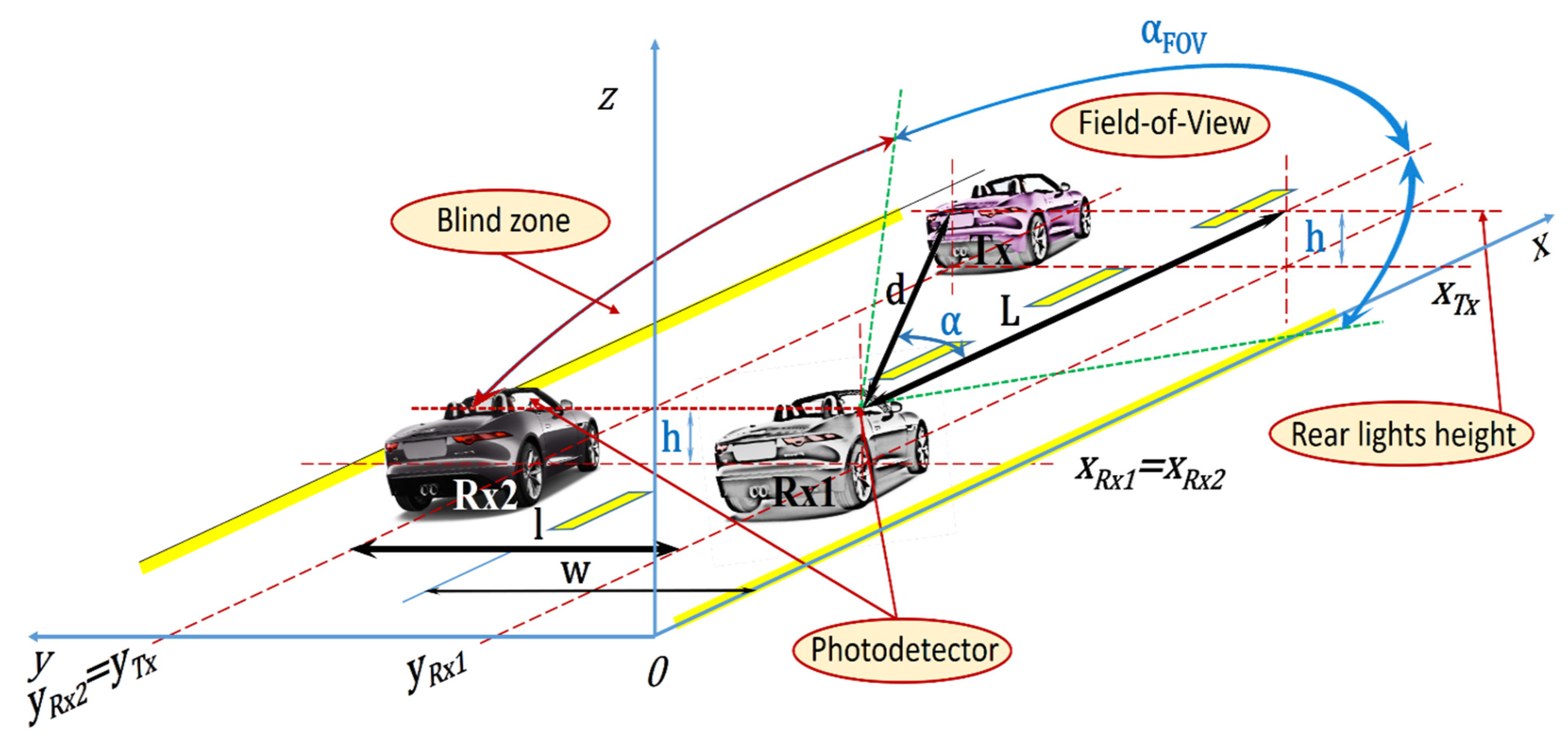
3. Analysis Concerning the Influence of the Incidence Angle on the Quality of the Vehicle-to-Vehicle Visible Light Communications Link
4. Experimental Determination of the Light Radiation Pattern of Commercial Vehicle Rear Lights
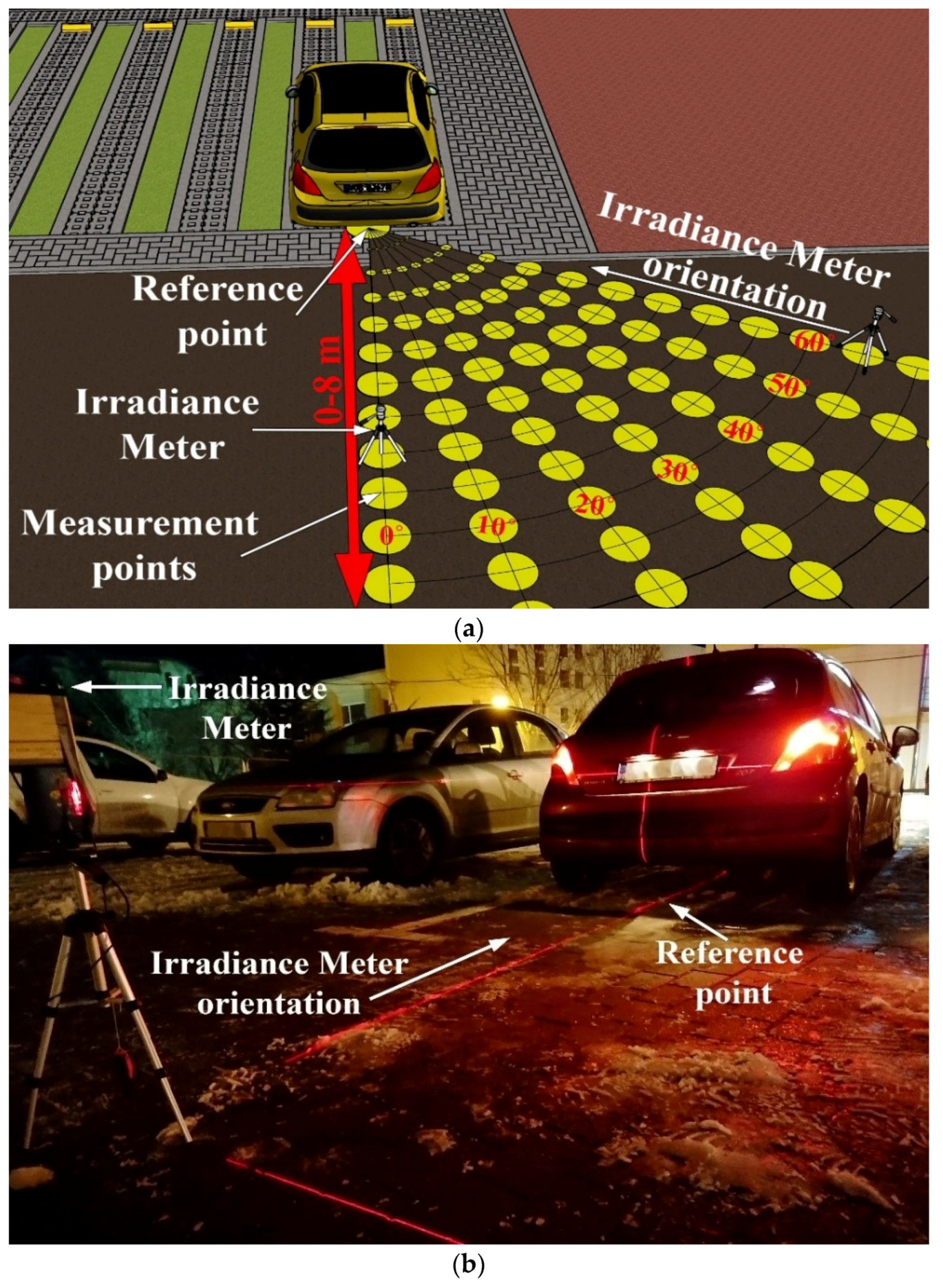
4.1. Measurement Settings
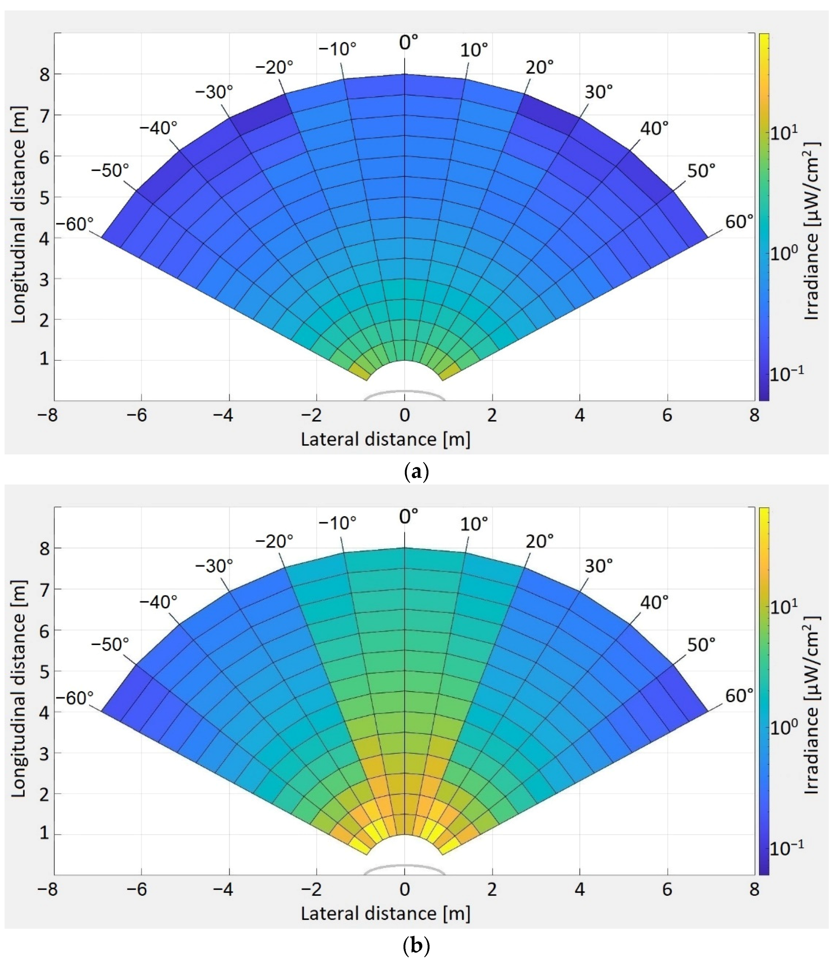
4.2. Discussion on Measurement Results
5. Description of the Vehicle-to-Vehicle Visible Light Communications Prototype
6. Outdoor Testing Procedure
7. Experimental Results
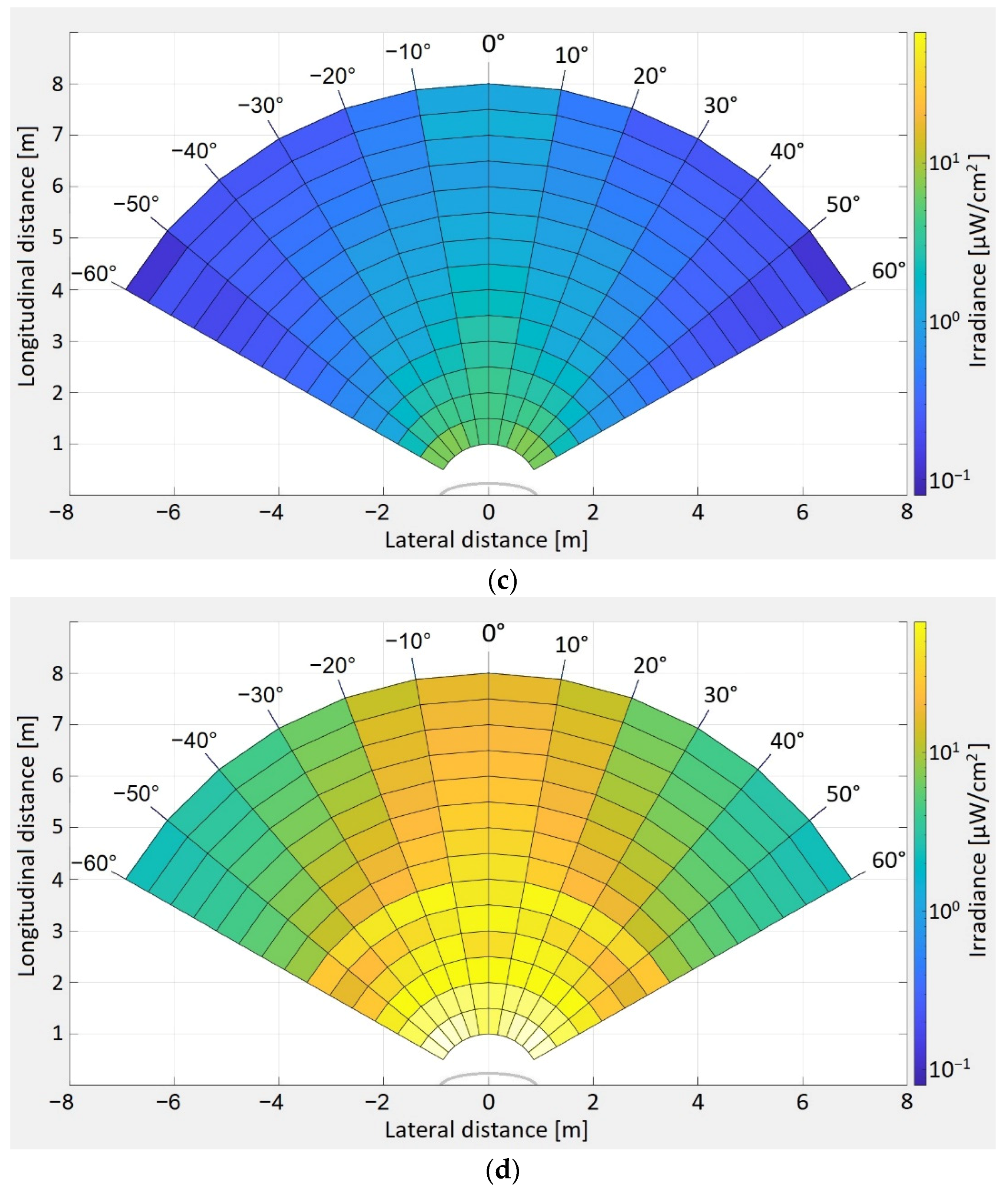
7.1. The Experimental Determination of the Light Radiation for the VLC Emitter
7.2. The Experimental Evaluation of the Effect of Vehicle Misalignment and of Inter-Vehicle Distance
8. Discussions on the Results, Contributions of this Work, and Perspectives
9. Conclusions
Author Contributions
Funding
Institutional Review Board Statement
Informed Consent Statement
Conflicts of Interest
References
- Matheus, L.E.M.; Vieira, A.B.; Vieira, L.F.M.; Vieira, M.A.M.; Gnawali, O. Visible Light Communication: Concepts, Applications and Challenges. IEEE Commun. Surv. Tutor. 2019, 21, 3204–3237. [Google Scholar] [CrossRef]
- Schirripa Spagnolo, G.; Cozzella, L.; Leccese, F. Underwater Optical Wireless Communications: Overview. Sensors 2020, 20, 2261. [Google Scholar] [CrossRef] [PubMed]
- Palacios Játiva, P.; Román Cañizares, M.; Azurdia-Meza, C.A.; Zabala-Blanco, D.; Dehghan Firoozabadi, A.; Seguel, F.; Montejo-Sánchez, S.; Soto, I. Interference Mitigation for Visible Light Communications in Underground Mines Using Angle Diversity Receivers. Sensors 2020, 20, 367. [Google Scholar] [CrossRef] [Green Version]
- Kim, S.-Y.; Kim, C.-M.; Koh, S.-J. Framework of IoT Services over Unidirectional Visible Lights Communication Networks. Electronics 2020, 9, 1349. [Google Scholar] [CrossRef]
- Delgado-Rajo, F.; Melian-Segura, A.; Guerra, V.; Perez-Jimenez, R.; Sanchez-Rodriguez, D. Hybrid RF/VLC Network Architecture for the Internet of Things. Sensors 2020, 20, 478. [Google Scholar] [CrossRef] [PubMed] [Green Version]
- Almadani, Y.; Plets, D.; Bastiaens, S.; Joseph, W.; Ijaz, M.; Ghassemlooy, Z.; Rajbhandari, S. Visible Light Communications for Industrial Applications—Challenges and Potentials. Electronics 2020, 9, 2157. [Google Scholar] [CrossRef]
- Ji, R.; Wang, S.; Liu, Q.; Lu, W. High-Speed Visible Light Communications: Enabling Technologies and State of the Art. Appl. Sci. 2018, 8, 589. [Google Scholar] [CrossRef] [Green Version]
- James Singh, K.; Huang, Y.-M.; Ahmed, T.; Liu, A.-C.; Huang Chen, S.-W.; Liou, F.-J.; Wu, T.; Lin, C.-C.; Chow, C.-W.; Lin, G.-R.; et al. Micro-LED as a Promising Candidate for High-Speed Visible Light Communication. Appl. Sci. 2020, 10, 7384. [Google Scholar] [CrossRef]
- Hussein, A.T.; Alresheedi, M.T.; Elmirghani, J.M.H. 20 Gb/s Mobile Indoor Visible Light Communication System Employing Beam Steering and Computer Generated Holograms. J. Lightwave Technol. 2015, 33, 5242–5260. [Google Scholar] [CrossRef]
- Bian, R.; Tavakkolnia, I.; Haas, H. 15.73 Gb/s Visible Light Communication With Off-the-Shelf LEDs. J. Lightwave Technol. 2019, 37, 2418–2424. [Google Scholar] [CrossRef] [Green Version]
- Tsonev, D.; Videv, S.; Haas, H. Towards a 100 Gb/s visible light wireless access network. Opt. Express 2015, 23, 1627–1637. [Google Scholar] [CrossRef] [PubMed]
- Zhang, Y.; Zhang, H.; Cosmas, J.; Jawad, N.; Ali, K.; Meunier, B.; Kapovits, A.; Huang, L.-K.; Li, W.; Shi, L.; et al. Internet of radio and light: 5G building network radio and edge architecture. Intell. Converg. Netw. 2020, 1, 37–57. [Google Scholar] [CrossRef]
- Chen, Y.-W.; Zhang, R.; Hsu, C.-W.; Chang, G.-K. Key Enabling Technologies for the Post-5G Era: Fully Adaptive, All-Spectra Coordinated Radio Access Network with Function Decoupling. IEEE Commun. Mag. 2020, 58, 60–66. [Google Scholar] [CrossRef]
- Alsharif, M.H.; Kelechi, A.H.; Albreem, M.A.; Chaudhry, S.A.; Zia, M.S.; Kim, S. Sixth Generation (6G) Wireless Networks: Vision, Research Activities, Challenges and Potential Solutions. Symmetry 2020, 12, 676. [Google Scholar] [CrossRef]
- Prince, G.B.; Little, T.D.C. Two-Phase Framework for Indoor Positioning Systems Using Visible Light. Sensors 2018, 18, 1917. [Google Scholar] [CrossRef] [Green Version]
- Zhuang, Y.; Hua, L.; Qi, L.; Yang, J.; Cao, P.; Cao, Y.; Wu, Y.; Thompson, J.; Haas, H. A Survey of Positioning Systems Using Visible LED Lights. IEEE Commun. Surv. Tutor. 2018, 20, 1963–1988. [Google Scholar] [CrossRef] [Green Version]
- Alsalami, F.M.; Ahmad, Z.; Zvanovec, S.; Haigh, P.A.; Haas, O.C.L.; Rajbhandari, S. Indoor Intruder Tracking Using Visible Light Communications. Sensors 2019, 19, 4578. [Google Scholar] [CrossRef] [Green Version]
- Pešek, P.; Zvanovec, S.; Chvojka, P.; Bhatnagar, M.R.; Ghassemlooy, Z.; Saxena, P. Mobile User Connectivity in Relay-Assisted Visible Light Communications. Sensors 2018, 18, 1125. [Google Scholar] [CrossRef] [Green Version]
- Gheth, W.; Rabie, K.M.; Adebisi, B.; Ijaz, M.; Harris, G. Performance Analysis of Cooperative and Non-Cooperative Relaying over VLC Channels. Sensors 2020, 20, 3660. [Google Scholar] [CrossRef]
- Mohammedi Merah, M.; Guan, H.; Chassagne, L. Experimental Multi-User Visible Light Communication Attocell Using Multiband Carrierless Amplitude and Phase Modulation. IEEE Access 2019, 7, 12742–12754. [Google Scholar] [CrossRef]
- Kumar, N.; Lourenço, N.; Terra, D.; Alves, L.N.; Aguiar, R.L. Visible light communications in intelligent transportation systems. In Proceedings of the 2012 IEEE Intelligent Vehicles Symposium, Madrid, Spain, 3–7 June 2012; p. 748. [Google Scholar] [CrossRef]
- Seminara, M.; Nawaz, T.; Caputo, S.; Mucchi, L.; Catani, J. Characterization of Field of View in Visible Light Communication Systems for Intelligent Transportation Systems. IEEE Photonics J. 2020, 12, 1–16, 7903816. [Google Scholar] [CrossRef]
- Avătămăniței, S.-A.; Căilean, A.-M.; Done, A.; Dimian, M.; Popa, V.; Prelipceanu, M. Design and Intensive Experimental Evaluation of an Enhanced Visible Light Communication System for Automotive Applications. Sensors 2020, 20, 3190. [Google Scholar] [CrossRef] [PubMed]
- Avătămăniței, S.-A.; Căilean, A.-M.; Done, A.; Dimian, M.; Popa, V. Experimental Evaluation of Traffic Light to Vehicle Visible Light Communications in Snowfall Conditions. In Proceedings of the 2020 7th International Conference on Control, Decision and Information Technologies (CoDIT), Prague, Czech Republic, 29 June–2 July 2020; pp. 693–696. [Google Scholar] [CrossRef]
- Islim, M.S.; Videv, S.; Safari, M.; Xie, E.; McKendry, J.J.; Gu, E.; Haas, H. The Impact of Solar Irradiance on Visible Light Communications. J. Lightwave Technol. 2018, 36, 2376–2386. [Google Scholar] [CrossRef] [Green Version]
- Avătămăniței, S.A.; Căilean, A.-M.; Done, A.; Dimian, M.; Prelipceanu, M. Noise Resilient Outdoor Traffic Light Visible Light Communications System Based on Logarithmic Transimpedance Circuit: Experimental Demonstration of a 50 m Reliable Link in Direct Sun Exposure. Sensors 2020, 20, 909. [Google Scholar] [CrossRef] [Green Version]
- Avătămăniţei, S.; Căilean, A.; Zadobrischi, E.; Done, A.; Dimian, M.; Popa, V. Intensive Testing of Infrastructure-to-Vehicle Visible Light Communications in Real Outdoor Scenario: Evaluation of a 50 meters link in Direct Sun Exposure. In Proceedings of the 2019 Global LIFI Congress (GLC), Paris, France, 12–13 June 2019; pp. 1–5. [Google Scholar] [CrossRef]
- Nawaz, T.; Seminara, M.; Caputo, S.; Mucchi, L.; Cataliotti, F.S.; Catani, J. IEEE 802.15.7-Compliant Ultra-Low Latency Relaying VLC System for Safety-Critical ITS. IEEE Trans. Veh. Technol. 2019, 68, 12040–12051. [Google Scholar] [CrossRef] [Green Version]
- Căilean, A.M.; Cagneau, B.; Chassagne, L.; Dimian, M.; Popa, V. Novel Receiver Sensor for Visible Light Communications in Automotive Applications. IEEE Sens. J. 2015, 15, 4632–4639. [Google Scholar] [CrossRef]
- Liu, Y.C.; Shiu, R.J.; Wei, L.Y.; Hsu, C.W.; Chow, C.W.; Yeh, C.H. 100-m Long Distance RGB Visible Light Camera Communication. In Proceedings of the 23rd Opto-Electronics and Communications Conference, Jeju Island, Korea, 2–6 July 2018; pp. 1–2. [Google Scholar] [CrossRef]
- Căilean, A.M.; Dimian, M.; Done, A. Enhanced design of visible light communication sensor for automotive applications: Experimental demonstration of a 130 meters link. In Proceedings of the 2018 Global LIFI Congress (GLC), Paris, France, 8–9 February 2018; pp. 1–4. [Google Scholar] [CrossRef]
- Han, S.; Wang, C.; Li, G.; Chi, N. A 427.5 Mbps Automotive Headlight Visible Light Communication System Utilizing 64QAM-DMT Modulation with Software Pre-equalization. In Proceedings of the IEEE/CIC International Conference on Communications in China (ICCC), Changchun, China, 11–13 August 2019; pp. 169–172. [Google Scholar] [CrossRef]
- Avătămăniţei, S.; Căilean, A.; Beguni, C.; Popa, V.; Dimian, M. Experimental Investigation of Visible Light Communications Coverage in Vehicle-to-Vehicle Applications. In Proceedings of the 2021 International Conference on Artificial Intelligence and Computer Science Technology (ICAICST), Tangerang Selatan, Indonesia, 29–30 June 2021; pp. 1–6. [Google Scholar]
- Căilean, A.M.; Dimian, M. Current Challenges for Visible Light Communications Usage in Vehicle Applications: A Survey. IEEE Commun. Surv. Tutor. 2017, 19, 2681–2703. [Google Scholar] [CrossRef]
- Nishimoto, S.; Nagura, T.; Yamazato, T.; Yendo, T.; Fujii, T.; Okada, H.; Arai, S. Overlay coding for road-to-vehicle visible light communication using LED array and high-speed camera. In Proceedings of the 14th International IEEE Conference on Intelligent Transportation Systems (ITSC), Washington, DC, USA, 5–7 October 2011; pp. 1704–1709. [Google Scholar] [CrossRef]
- Cailean, A.; Cagneau, B.; Chassagne, L.; Topsu, S.; Alayli, Y.; Blosseville, J. Visible light communications: Application to cooperation between vehicles and road infrastructures. In Proceedings of the 2012 IEEE Intelligent Vehicles Symposium, Madrid, Spain, 3–7 June 2012; p. 1055. [Google Scholar] [CrossRef] [Green Version]
- Takai, I.; Ito, S.; Yasutomi, K.; Kagawa, K.; Andoh, M.; Kawahito, S. LED and CMOS Image Sensor Based Optical Wireless Communication System for Automotive Applications. IEEE Photonics J. 2013, 5, 6801418. [Google Scholar] [CrossRef]
- Cahyadi, W.A.; Chung, Y.H.; Ghassemlooy, Z.; Hassan, N.B. Optical Camera Communications: Principles, Modulations, Potential and Challenges. Electronics 2020, 9, 1339. [Google Scholar] [CrossRef]
- Memedi, A.; Dressler, F. Vehicular Visible Light Communications: A Survey. IEEE Commun. Surv. Tutor. 2021, 23, 161–181. [Google Scholar] [CrossRef]
- Forkel, G.J.M.; Krohn, A.; Hoeher, P.A. Optical Interference Suppression Based on LCD-Filtering. Appl. Sci. 2019, 9, 3134. [Google Scholar] [CrossRef] [Green Version]
- Avătămăniţei, S.; Căilean, A.; Beguni, C.; Dimian, M.; Popa, V. Analysis Concerning the Usage of Visible Light Communications in Automotive Applications: Achievable Distances vs. Optical Noise. In Proceedings of the 2020 International Conference on Development and Application Systems (DAS), Suceava, Romania, 21–23 May 2020; pp. 121–126. [Google Scholar] [CrossRef]
- Kim, Y.H.; Cahyadi, W.A.; Chung, Y.H. Experimental Demonstration of VLC-Based Vehicle-to-Vehicle Communications Under Fog Conditions. IEEE Photonics J. 2015, 7, 7905309. [Google Scholar] [CrossRef]
- Eso, E.; Burton, A.; Hassan, N.B.; Abadi, M.M.; Ghassemlooy, Z.; Zvanovec, S. Experimental Investigation of the Effects of Fog on Optical Camera-based VLC for a Vehicular Environment. In Proceedings of the 2019 15th International Conference on Telecommunications (ConTEL), Graz, Austria, 3–5 July 2019; pp. 1–5. [Google Scholar] [CrossRef]
- Shen, W.; Tsai, H. Testing vehicle-to-vehicle visible light communications in real-world driving scenarios. In Proceedings of the 2017 IEEE Vehicular Networking Conference (VNC), Torino, Italy, 27–29 November 2017; pp. 187–194. [Google Scholar] [CrossRef]
- Yamazato, T.; Takai, I.; Okada, H.; Fujii, T.; Yendo, T.; Arai, S.; Andoh, M.; Harada, T.; Yasutomi, K.; Kagawa, K.; et al. Image-sensor-based visible light communication for automotive applications. IEEE Commun. Mag. 2014, 52, 88–97. [Google Scholar] [CrossRef]
- Zhang, Y.; Zhang, M.; Zhou, H.; Sun, Y.; Wei, C.; He, W. A Long Distance Real-time DPSK Visible Light Communication System Based on FPGA. In Proceedings of the 18th International Conference on Optical Communications and Networks, Huangshan, China, 5–8 August 2019; pp. 1–3. [Google Scholar] [CrossRef]
- Căilean, A.M.; Dimian, M. Toward Environmental-Adaptive Visible Light Communications Receivers for Automotive Applications: A Review. IEEE Sens. J. 2016, 16, 2803–2811. [Google Scholar] [CrossRef]
- Căilean, A.-M.; Dimian, M.; Popa, V. Noise-Adaptive Visible Light Communications Receiver for Automotive Applications: A Step Toward Self-Awareness. Sensors 2020, 20, 3764. [Google Scholar] [CrossRef]
- Abualhoul, M.Y.; Shagdar, O.; Nashashibi, F. Visible Light inter-vehicle Communication for platooning of autonomous vehicles. In Proceedings of the 2016 IEEE Intelligent Vehicles Symposium (IV), Gothenburg, Sweden, 19–22 June 2016; pp. 508–513. [Google Scholar] [CrossRef] [Green Version]
- Béchadergue, B.; Chassagne, L.; Guan, H. Suitability of visible light communication for platooning applications: An experimental study. In Proceedings of the 2018 Global LIFI Congress (GLC), Paris, France, 8–9 February 2018; pp. 1–6. [Google Scholar] [CrossRef]
- Uçar, S.; Ergen, S.Ç.; Özkasap, Ö. Security vulnerabilities of autonomous platoons. In Proceedings of the 2017 25th Signal Processing and Communications Applications Conference (SIU), Antalya, Turkey, 15–18 May 2017; pp. 1–4. [Google Scholar] [CrossRef]
- Ucar, S.; Ergen, S.C.; Ozkasap, O. IEEE 802.11p and Visible Light Hybrid Communication Based Secure Autonomous Platoon. IEEE Trans. Veh. Technol. 2018, 67, 8667–8681. [Google Scholar] [CrossRef]
- Hardes, T.; Sommer, C. Towards Heterogeneous Communication Strategies for Urban Platooning at Intersections. In Proceedings of the 2019 IEEE Vehicular Networking Conference (VNC), Los Angeles, CA, USA, 4–6 December 2019; pp. 1–8. [Google Scholar] [CrossRef]
- Masini, B.M.; Bazzi, A.; Zanella, A. A Survey on the Roadmap to Mandate on Board Connectivity and Enable V2V-Based Vehicular Sensor Networks. Sensors 2018, 18, 2207. [Google Scholar] [CrossRef] [Green Version]
- Zadobrischi, E.; Cosovanu, L.-M.; Dimian, M. Traffic Flow Density Model and Dynamic Traffic Congestion Model Simulation Based on Practice Case with Vehicle Network and System Traffic Intelligent Communication. Symmetry 2020, 12, 1172. [Google Scholar] [CrossRef]
- Marabissi, D.; Mucchi, L.; Caputo, S.; Nizzi, F.; Pecorella, T.; Fantacci, R.; Nawaz, T.; Seminara, M.; Catani, J. Experimental Measurements of a Joint 5G-VLC Communication for Future Vehicular Networks. J. Sens. Actuator Netw. 2020, 9, 32. [Google Scholar] [CrossRef]
- Abualhoul, M.Y.; Munoz, E.T.; Nashashibi, F. The Use of Lane-Centering to Ensure the Visible Light Communication Connectivity for a Platoon of Autonomous Vehicles. In Proceedings of the 2018 IEEE International Conference on Vehicular Electronics and Safety (ICVES), Madrid, Spain, 12–14 September 2018; pp. 1–6. [Google Scholar] [CrossRef] [Green Version]
- Cuba-Zúñiga, D.J.; Mafra, S.B.; Mejía-Salazar, J.R. Cooperative Full-Duplex V2V-VLC in Rectilinear and Curved Roadway Scenarios. Sensors 2020, 20, 3734. [Google Scholar] [CrossRef]
- Memedi, A.; Tsai, H.; Dressler, F. Impact of Realistic Light Radiation Pattern on Vehicular Visible Light Communication. In Proceedings of the GLOBECOM 2017—2017 IEEE Global Communications Conference, Singapore, 4–8 December 2017; pp. 1–6. [Google Scholar] [CrossRef]
- Eldeeb, H.B.; Eso, E.; Uysal, M.; Ghassemlooy, Z.; Zvanovec, S.; Sathian, J. Vehicular Visible Light Communications: The Impact of Taillight Radiation Pattern. In Proceedings of the 2020 IEEE Photonics Conference (IPC), Vancouver, BC, Canada, 28 September–1 October 2020; pp. 1–2. [Google Scholar] [CrossRef]
- Motorways. 2018. Available online: https://ec.europa.eu/transport/road_safety/sites/roadsafety/files/pdf/ersosynthesis2018-motorways.pdf (accessed on 5 March 2021).
- Kahn, J.M.; Barry, J.R. Wireless infrared communications. Proc. IEEE 1997, 85, 265–298. [Google Scholar] [CrossRef] [Green Version]
- Al-Kinani, A.; Wang, C.; Zhou, L.; Zhang, W. Optical Wireless Communication Channel Measurements and Models. IEEE Commun. Surv. Tutor. 2018, 20, 1939–1962. [Google Scholar] [CrossRef]
- Karbalayghareh, M.; Miramirkhani, F.; Eldeeb, H.B.; Kizilirmak, R.C.; Sait, S.M.; Uysal, M. Channel Modelling and Performance Limits of Vehicular Visible Light Communication Systems. IEEE Trans. Veh. Technol. 2020, 69, 6891–6901. [Google Scholar] [CrossRef]
- Cailean, A.; Cagneau, B.; Chassagne, L.; Dimian, M.; Popa, V. Miller code usage in Visible Light Communications under the PHY I layer of the IEEE 802.15.7 standard. In Proceedings of the 2014 10th International Conference on Communications (COMM), Bucharest, Romania, 29–31 May 2014; pp. 1–4. [Google Scholar] [CrossRef] [Green Version]
- United Nations. Agreement Concerning the Adoption of Uniform Technical Prescriptions for Wheeled Vehicles, Equipment and Parts Which Can be Fitted and/or be Used on Wheeled Vehicles and the Conditions for Reciprocal Recognition of Approvals Granted on the Basis of these Prescriptions; Addendum 6: Regulation No. 7. Revision 5—Amendment 2; United Nations: New York, NY, USA, 24 February 2011. [Google Scholar]
- Cailean, A.; Dimian, M. Impact of IEEE 802.15.7 Standard on Visible Light Communications Usage in Automotive Applications. IEEE Commun. Mag. 2017, 55, 169–175. [Google Scholar] [CrossRef]
- Cailean, A.; Cagneau, B.; Chassagne, L.; Topsu, S.; Alayli, Y.; Dimian, M. Visible light communications cooperative architecture for the intelligent transportation system. In Proceedings of the 2013 IEEE 20th Symposium on Communications and Vehicular Technology in the Benelux (SCVT), Namur, Belgium, 21 November 2013; pp. 1–5. [Google Scholar] [CrossRef]
- Eso, E.; Pesek, P.; Chvojka, P.; Ghassemlooy, Z.; Zvanovec, S.; Sathian, J. A Relay-Assisted Vehicular Visible Light Communications Network. In Proceedings of the 2020 IEEE Photonics Conference (IPC), Vancouver, BC, Canada, 28 September–1 October 2020; pp. 1–2. [Google Scholar] [CrossRef]
- Zaki, R.W.; Fayed, H.A.; Abd El Aziz, A.; Aly, M.H. Outdoor Visible Light Communication in Intelligent Transportation Systems: Impact of Snow and Rain. Appl. Sci. 2019, 9, 5453. [Google Scholar] [CrossRef] [Green Version]


| Parameter | Feature/Values |
|---|---|
| Optical source | Commercial vehicle LED rear lights |
| Emitted Irradiance | No stronger than the one of existing commercial vehicles (see details in Figure 5 and in Section 7.1) |
| VLC emitter center wavelength | 620 nm |
| Available modulation techniques | DSSS, OOK |
| Available coding techniques | SIK, Manchester, Miller |
| Available data rates | 3–200 kb/s |
| VLC emitter height | 74 cm (similar to a real vehicle) |
| Distance between the two stoplights | 90 cm (similar to a real vehicle) |
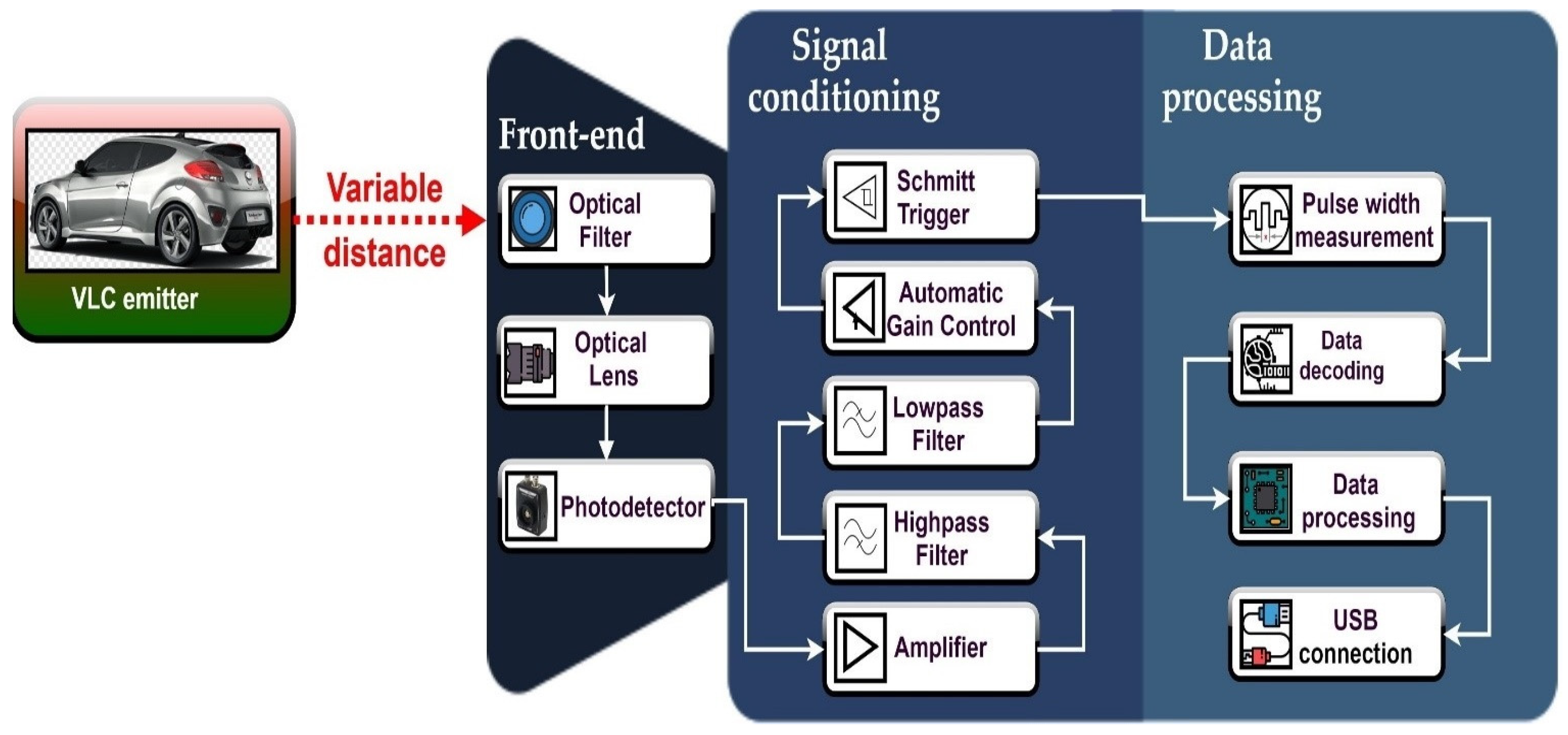
| VLC Receiver Stage | Parameter | Feature/Values |
|---|---|---|
| Front-end | VLC receiver FOV | ±53° respectively ±20° |
| VLC optical receiver | PDA100A optical detector with adjustable gain | |
| VLC receiver optical filter center wavelength | 645 ± 40 nm | |
| Signal conditioning | Amplification | Up to 5000 gain, with automatic gain control |
| Signal filtering |
| |
| Square signal reconstruction | Based on Schmitt trigger circuit | |
| Data processing | Hardware | Microcontroller board based on an ARM Cortex M4 180 MHz processor |
| Data processing | Based on rising and falling edge identification and pulse width measurement | |
| Data decoding | Real-time data extraction for data modulated using DSSS and OOK modulation, SIK, Manchester and Miller coding, with data rates between 3–200 kb/s | |
| Monitored parameters | Real-time BER computing without forward error correcting codes | |
| Other VLC receiver parameters | Height of the optical detector | 74 cm |
| Parameter | Feature/Values |
|---|---|
| Testing conditions | Outdoor, uncontrolled conditions |
| Testing scenario | Two lane V2V communication with:
|
| Lighting conditions |
|
| VLC emitter | LED-based vehicle rear lights |
| VLC emitter height | 74 cm (i.e., similar as commercial vehicles) |
| Distance between the two vehicle rear lights | 90 cm (i.e., similar to the case of a commercial vehicle) |
| Width of a lane | 3.5 m |
| Emitter–Receiver (V2V) distance | 1–75 m |
| Emitter–Receiver (V2V) angle | 0°–49° |
| VLC receiver | Photodiode-based |
| VLC receiver height | 74 cm |
| Modulation technique | OOK |
| Coding technique | Manchester |
| Data rate | 100 kb/s |
| Measured parameter | Real-time BER determination without the usage of forward error correcting protocols |
Publisher’s Note: MDPI stays neutral with regard to jurisdictional claims in published maps and institutional affiliations. |
© 2021 by the authors. Licensee MDPI, Basel, Switzerland. This article is an open access article distributed under the terms and conditions of the Creative Commons Attribution (CC BY) license (https://creativecommons.org/licenses/by/4.0/).
Share and Cite
Avătămăniței, S.-A.; Beguni, C.; Căilean, A.-M.; Dimian, M.; Popa, V. Evaluation of Misalignment Effect in Vehicle-to-Vehicle Visible Light Communications: Experimental Demonstration of a 75 Meters Link. Sensors 2021, 21, 3577. https://doi.org/10.3390/s21113577
Avătămăniței S-A, Beguni C, Căilean A-M, Dimian M, Popa V. Evaluation of Misalignment Effect in Vehicle-to-Vehicle Visible Light Communications: Experimental Demonstration of a 75 Meters Link. Sensors. 2021; 21(11):3577. https://doi.org/10.3390/s21113577
Chicago/Turabian StyleAvătămăniței, Sebastian-Andrei, Cătălin Beguni, Alin-Mihai Căilean, Mihai Dimian, and Valentin Popa. 2021. "Evaluation of Misalignment Effect in Vehicle-to-Vehicle Visible Light Communications: Experimental Demonstration of a 75 Meters Link" Sensors 21, no. 11: 3577. https://doi.org/10.3390/s21113577