1. Introduction
Fire detection and evacuation are an important issue in today’s multi-floor building construction. In the existing evacuation approach, evacuees in the building are evacuated by following the evacuation sign on the wall to the emergency exits. However, evacuees following the fixed evacuation sign to the nearest emergency may be stuck on the route when the fire spread to the emergency route. This calls for an intelligent evacuation path that can bypass the fire zone to the emergency exit in a timely manner. In a contemporary multi-floor building, temperature sensors and smoke sensors are deployed to detect and issue an alarm when there is a fire or smoke in the building. These sensors are connected by wired or wireless networks to enable the IoT capabilities in monitoring and capturing the fire signal in the buildings. When the fire signal is detected, the most important thing is to identify the evacuation path in the buildings.
The temperature data collected by the temperature sensors deployed in the building can provide useful information for planning the evacuation path. Basically, the temperature sensors will periodically sense, collect and transmit the temperature data back to the control station, also known as the sink node. Instead of a traditional fixed evacuation path, a temperature-aware evacuation path should be designed to provide a safer evacuation route by using the temperature data collected by the sensors. In a fire zone that has a very high-temperature or is full of inflammable materials (e.g., paper, wood, plastic), the fire spreading can be very fast so as to increase the temperature dramatically in a very short period of time. In addition, evacuation in a large multi-floor building should adapt to the temperature changes because of longer evacuation time. Hence, the evacuation path should be re-calculated and rerouted at every time slot to acquire the most recent temperature data.
Evacuation path planning has been studied in recent years; most focus on the evacuation path planning in a two-dimensional graph. However, these algorithms are not applicable to the three-dimensional multi-floor buildings. In addition, most of the previous research calculates the evacuation path based on one-shot temperature data captured by the sensors. This one-shot temperature data calculated evacuation path is not valid in the large multi-floor buildings where the temperature can change dramatically in the fire environments during evacuation.
According to the fire research in [
1], fire progression rapidly in minutes. The temperature can reach 500 °F within three to four minutes in the incipient stage of today’s fire environments. The flashover stage that is over 1100 °F can develop under five minutes. It is reported in [
1] that the upper limit of human temperature tenability is 212 °F or 100 °C. In addition, the experiments in [
2] show that deaths by a thermal injury occurring at a temperature of 350 °F in three minutes. Another result in [
3] shows that the critical time for the fire is 5.5 min; after this time, the fire spread quickly to the other parts of the building. This indicates that the people evacuation time window is very limited. In addition, the temperature increasing rate on the evacuation path may be faster than the people evacuation time, so the evacuation path should be adaptable based on current temperature data. In other words, the evacuation path should be adjusted to bypass the fire zone based on temperature data acquired by the sensors at the current time slot. Evacuation at large multi-floor buildings needs more time than the evacuation path algorithm should address the fire spreading on a timely basis. This calls for a new three-dimensional evacuation path planning algorithm that can adapt its path based on most current temperature data from the sensors.
Note that most injuries and deaths are caused by smoke in the fire. Human exposes to toxic gases (e.g., carbon monoxide concentration of 0.1% to 0.8%) within one or two minutes will become incapacitated in movement [
4]. In [
5], they show that there is a linear relationship between temperature rise and carbon monoxide concentration in the fire. Hence, the higher temperature, the higher the carbon monoxide concentration. In this paper, without loss of generality, the temperature data acquired by the temperature sensor is used as the hazard index of toxic smoke concentration and the heat radiation from the flame.
Figure 1 shows an illustrative example of evacuation path planning in different time slots in a three-floor building where each floor has a grid size of 10
10. In this example, 100 temperature sensors are deployed at each floor, and 300 deployed sensors are deployed in the three-floor building. How to determine the grid size (or sensor density) at each floor depends on the tradeoff between evacuation speed and fire spreading speed. In
Section 5, we will show that the proposed algorithms can help to determine the best density of deployed temperature sensors in the building.
In
Figure 1, the number in blue color indicates the node ID, and the number in red color indicates the temperature at that node. In
Figure 1a, the fire is first detected at node 92, and the evacuation path is shown as the green color line from node ID 201→291→91 at the first time slot. In
Figure 1b, we assume people can move at most three hops distance in one time slot. Then after three time slots, the user can move from location 201 to location 291. At the same time, we also assume the fire spreads to the neighbor nodes in one hop distance at each time slot. After three time slots, the temperature at the emergency exit at node 91 is 140 °C. In this case, a new evacuation path should be identified because the temperature at location 91 is higher than the upper limit of human temperature tenability, 100 °C. The new evacuation path is shown as the green line in
Figure 1b. Then an interesting research question is how to design and plan a minimum total temperature and a minimum evacuation time evacuation path in considering the temperature changes in the different time slots.
In this paper, we first propose the mathematical models to capture this evacuation path planning problem in the multi-story multi-exit buildings and then develop the temperature-aware and time-aware algorithms based on the temperature data periodically captured by the temperature sensors. In the proposed mathematical models and evacuation path algorithms, we generalized the path cost metric to address the time cost and the temperature cost. When using the total time slots as the cost metric, the proposed evacuation path algorithm identifies the path that can evacuate people as fast as possible and in-the-meantime to bypass the fire zone. When using the total temperature on the evacuation path as the cost metric, the proposed evacuation path algorithms identify the comfortable evacuation path with the minimum total temperature on the evacuation path.
The contribution of this paper is the proposed multi-time-slot-aware evacuation algorithm that can help the evacuees to evacuate in the most efficient way. To distribute the calculated evacuation path to the evacuee on a timely basis, another three components should be constructed in the system. The first is the temperature sensors that will report the sensing temperature data back to the control center. The second is the control center that calculates the evacuation path by using the proposed algorithms for each user and distribute the evacuation path to the user’s app. The third is the user’s app that shows the evacuation path from the control center and reports his/her location to the nearby Wi-Fi APs.
We summarize the contributions of this paper.
Novel time and temperature aware evacuation path (TTAEP) model: We propose a rigorous mathematical model, TTAEP, to capture the evacuation path planning problem in the multi-story multi-exit building with addressing to the temperature changes in different time slots.
Novel time aware and temperature aware evacuation path planning algorithm: Six evacuation algorithms are devised to tackle the TTAEP problem where the objective is to identify the evacuation path with minimum evacuation time and minimum total temperature on the path. The basic idea of the proposed algorithms is to identify the multi-staged best paths to adapt to the temperature changes at each stage. By using the most recent sensed temperature data return from the sensors, the proposed algorithms identify the multi-staged evacuation path.
Helps to determine the density of deploying temperature sensors in the building: From the computational experiments in the Taipei 101 Shopping Mall, we observe that the density of deployed temperature sensors in the building plays a non-negligible role in determining the efficiency of the evacuation paths and the best sensor density should consider the tradeoff between evacuation speed and fire spreading speed. The computational experiments of the proposed algorithms can help to determine the best density of deployed temperature sensors in the building.
Helps to determine the maximum people capacity in the building: From the computational experiments in the Taipei 101 Shopping Mall, we observe that at most 800 people can be successfully evacuated within 15 time slots in the extreme case of seven fires. The computational experiments of the proposed algorithms can help to determine the maximum people capacity in the building in considering the evacuation process.
2. Related Works
With the rapid development of sensor technologies and IoT technologies, temperature aware evacuation services are possible in state-of-the-art IoT buildings. Home-based fire detection and alert system prototype were built in [
6] by adopting the Arduino board to connect and control temperature sensors, flame sensors and ZigBee technology for transmission module. Another prototype was designed and implemented in [
7] to monitor and control the industrial environment by using the Wi-Fi communication module. Hardware solutions, which include RFID platform and temperature sensors, have been designed and implemented in [
8] to enable emergency evacuation services in IoT based buildings. In [
8], the RFID platform, which includes the RFID tags and RFID readers, is implemented to locate the people in the buildings. Based on the temperature data acquired by the implemented temperature sensors in [
8] and the people position information based on the RFID solutions implementation in [
8], the central computer can activate the emergency evacuation when a fire is detected. Wireless sensor networks for real-time fire detection are designed and evaluated in [
9] to enable fire safety in the home environment. An evacuation support system in large areas is proposed in [
10]. The system’s architecture includes the emergency operation centers, localized operation center, smartphone app and wireless backbone networks are described in [
10] to show that evacuation support system based on IoT network can adapt to dynamic conditions in the networks and guide the people to the safe places. In [
11], they proposed an integrated framework, including the cloud computing center to collect and compute the system information and an indoor localization system based on Bluetooth to locate and evacuate evacuees to the safe zone.
An evacuation route planning algorithm has been proposed in recent studies. In [
12,
13], a shortest-path-based algorithm is proposed to guide the evacuees to the nearest exit. In [
14,
15], the evacuation algorithms based on ant colony algorithm is proposed and simulated. The basic idea of the ant colony algorithm is based on the cooperative behavior of the evacuee to search for a safe emergency exit. In [
16], the bee colony optimization approach is proposed to find the evacuation path via the idea of swarm intelligence from the bee colony. In [
17], the first multi-exit evacuation algorithm is proposed to evacuate crowded people in large buildings. The basic idea in [
17] is to partition the evacuees into groups and evacuate each group to its nearest exit. To avoid congestion problems at the exits, the departure time of each group is calculated and delayed in its evacuation sequence. In [
11], a risk score based on the weighted sum of risk factors (includes temperature, visibility, CO density, etc.) for each possible evacuation path is calculated to identify the safe evacuation route. In [
18], Dijkstra’s shortest path evacuation path algorithm is proposed to identify the best route based on the risk assessment of numerically simulated fire scenarios.
Evacuation in the open space from disaster or terrorist attack has been proposed in [
19]. As compared to the building environment, it is not easy to install the sensors in the open space to acquire the data from the environment. Lacking environmental data, the evacuation strategy relies on the evacuee’s personal judgment and group behavior. Such kind of evacuation leveraging on evacuee’s individual intelligence and swarm intelligence also has been applied in high rise building [
20].
Evacuee’s behavior is an important factor in the evacuation success rate. In [
21], they found out that occupants will not immediately evacuate their residence when they hear a fire alarm because they think it is a drill or false alarm. Interestingly, if the occupants are informed of the fire locations and evacuation path, the reluctance to evacuate is reduced so as to speed-up the evacuation. In [
22], they propose an emotional contagion model of the crowded people in the fire. They found out that evacuee’s degree of panic is determined by accident information, evacuee’s knowledge and comfort level. Moreover, accident information can be provided by IoT devices to help reduce the degree of panic. In [
23], simulations show that evacuee’s evacuation behavior is seriously affected by the fire. The smoke spreading process and the effects on evacuees will be smaller at the exit that is far from the fire. The effect of environmental knowledge in evacuation has been studied in [
24]. The results show that visitors need longer evacuation time than occupants with the knowledge of the building.
Fire and evacuation simulation models have been proposed in recent research. In [
25], fire and evacuation software is developed to simulate the evacuation time in various environmental scenarios. Another study in [
26] proposed a fire evacuation simulation technique to capture the movement of evacuees with considering the fire spread. In [
27], agent-based models that consist of four agents (evacuees, fire, smoke and alarm) are proposed and simulated at supermarkets. When temperature data in the building is not available, the evacuee’s personal decisions will determine the evacuation success rate. In [
28], an exit choice model was proposed and simulated by assuming the fire spreading, and the crowdedness of the exits can be predicted by the evacuee. Fire and evacuation simulations done in [
29] are used to reconstruct a fatal fire that occurred in an indoor shooting range in Pusan, Korea, in 2009. They found out that occupants’ response time is the most important factor in an evacuation. Computational experiments and simulations are performed in [
30] to improve evacuation efficiency in different settings of fire scenarios and evacuee compositions. Fire and evacuation simulations [
31] and fire evacuation system [
32] were performed at the historical museum [
31] and historical theatres [
32] in Italy to increase the evacuation efficiency without altering the architectural characteristics of historical buildings.
The fire evacuation problem is a complex and highly dynamic problem. Until now, there are no international standards on the verification and validation of building fire evacuation models [
33]. In [
33], they suggest five main components of the fire evacuation model should be included, namely evacuation time, movement and navigation, exit usage, route availability and flow constraints. The fire evacuation model in large buildings needs to address more on the building architecture and floor plan that determines the evacuation routes. Artificial neural network (ANN) based fire evacuation algorithm is proposed in [
34] to identify the best evacuate route by calculating the risk value on each link. However, fire evacuation planning by ANN algorithm or reinforcement learning algorithm is a challenging problem because there is no standard benchmark environment to train these artificial intelligence agents. The first fire evacuation environment to train reinforcement learning agents for evacuation planning is proposed in [
35].
To summarize, even though there are many evacuation algorithms proposed in the literature, most of these algorithms are a one-shot algorithm where they do not address the temperature changing problem in the evacuation. In particular, how to identify a temperature-aware evacuation path in the multi-story multi-exit building is still not explored yet. In this paper, we capture the temperature changes at each time slot and propose a novel mathematical model and algorithms to identify the efficient evacuation path in a multi-story multi-exit building.
3. Graph Mapping Scheme from Three-Dimension Building to Two-Dimension Graph
To successfully develop the evacuation path in a multi-floor building, it is important to capture the building’s information in the three-dimension structure at the first stage. The floor plan information (including the sensor locations, doors, walls and obstacles) at each floor must be captured. In addition, the staircase that connects each floor also must be identified. As it is known that it is easier to develop the evacuation path algorithm in a two-dimensional graph. We first develop a graph mapping scheme that transforms the three-dimensional multi-floor building into a two-dimensional graph.
First, let
indicates the set of possible locations to deploy a temperature sensor in the multi-floor building. The location
in set
indicates the location to deploy a temperature sensor at location (
i,
j) on floor
k where
. Here, set
I indicates the set of X-axis locations; set
J indicates the set of Y-axis locations and set
K indicates the set of floor locations in the multi-floor building. Then the total number of locations to deploy the sensors is
. Next, let
indicates the corresponding node ID number at location (
i,
j) on floor
k and
where
is the set of nodes on the planar graph. To transform the three-dimensional multi-floor building to the two-dimensional planar graph, each node in
will associate with a node in
and this is a one-to-one mapping. Then we have Equation (1),
Next, we assign the node ID number
. The node ID assignment starts with the top left position
at the lowest floor in the building and all the way to the bottom-right position
on the highest floor in the building. The mapping is a row-based mapping that after all the positions in row
i is associated with a node ID, then next move to the positions in row
. Then for any
, the node ID
is calculated at Equation (2).
A staircase is a connection between the upper and lower floor of the building. Let there are two staircases in the building where the location is at the bottom corner of each floor. For the highest floor (i.e., th floor), the two staircase locations are at the bottom left position, and bottom-right position that connects to the bottom left position and bottom-right position at the th floor, respectively. For the lowest floor (i.e., first floor), the two staircase locations are at the bottom left position and bottom-right position that connects to the bottom left position and bottom-right position at the second floor, respectively. For any k floor that is neither the highest floor nor the first floor (i.e., ), there are also two staircase locations. The two staircase locations are at the bottom left position and bottom-right position that connects to the bottom left position and bottom-right position at the floor, respectively. In addition, these two staircase locations also connect to the bottom left position and bottom-right position at the floor, respectively.
Based on Equation (2) and the above arguments, the node ID number for the left staircase at the
th floor is shown in Equation (3).
In addition, the node ID number for the right staircase at the
th floor is shown in Equation (4).
In
Figure 1, we illustrate an example of a three-floor building where each floor has a grid size of 10
10. The number with the blue color indicates the node ID in
Figure 1. In this case,
,
and
. In
Figure 1, each floor has 100 locations to deploy a temperature sensor. According to Equation (2), the node ID for location (10, 2, 1) on the first floor is
.
After getting the node ID, the next step is to set up the links to connect the nodes in the planar graph. Basically, for any location in
that is not the staircase location; there is a link to each of four its neighboring locations (i.e., up to the location, down the location, left the location and right location) on the same floor
k. Let set
denote the set of links in the planar graph. Then,
, we have
The reason why we have
in (5) is that the locations in the first row do not have the up neighbors. Likewise,
in (6) is because the locations in the last row do not have the down neighbors;
in (7) is because the locations in the first column do not have the left neighbors;
in (8) is because the locations in the last column do not have the right neighbors. Next, we set up the links to connect the upper location and the lower location at the staircase.
Based on Equations (5)–(10), the total number of links in the planar graph is calculated in Equation (11). In Equation (11), the first term is to calculate the total links for all four directions of every node. The second term is to deduct the number of links that the nodes do not have their neighbors. The third term is to add the number of links that connect the staircase locations. For the three-floor building example shown in
Figure 1, there are 1088 links to be set in the planar graph.
Based on the Equations (1)–(4) to determine the node ID and Equations (5)–(10) to determine the link ID, we successfully transform the multi-floor building locations to the planar graph. In the next section, we will describe the algorithms to identify the efficient evacuation path in the multi-story multi-exit building.
4. Mathematical Model for Evacuation Path Planning in Multi-Story Multi-Exit Building
In this section, we propose the mathematical model to capture the evacuation path planning in the multi-floor building. The set of nodes and links in the planar graph constructed in the previous section are used as the input parameters to the following mathematical models. The basic idea of this mathematical model is to identify the minimum cost evacuation path in the multi-floor building. We generalize the model to identify the cost-efficient evacuation path. The cost can be the number of steps to evacuate from the building or the total temperature along the evacuation path. By setting the cost to be the number of steps to evacuate from the building, it is to minimize the time to evacuate. By setting the cost to be the total temperature along the evacuation path, it is to identify the evacuation path that can avoid the fire zone.
In the following, we first propose the mathematical model to capture the evacuation path planning in the multi-floor building.
4.1. Evacuation Path (EP) Model
First, we give the notations used in the formulation as follows:
Input values:
: the set of users;
: the set of evacuation path selected by user ;
L: the set of possible links on the planar graph;
E: the set of emergency exit nodes on the planar graph;
M: the upper limit of human temperature tenability (e.g., 100 °C);
: the link cost on link ;
: the temperature on link ;
: the indication function, = 1 when the link l is on the evacuation path p; = 0, otherwise;
: the indication function, = 1 when the node e is on the evacuation path p; = 0, otherwise;
Decision variables:
: =1 if evacuation path p is selected where ; =0, otherwise;
: =1 if link l is on the selected evacuation path where ; =0, otherwise. |
The EP mathematical model formulation is proposed as follows:
In problem (P1), the objective function is to minimize the total cost on the evacuation path. Constraints (14) and (16) enforce that there is an evacuation path for every user . Constraints (12) and (16) enforce that = 1 when link l is on the evacuation path. Constraint (13) enforces for the temperature on any selected link cannot exceed the upper limit of human temperature tenability M. This constraint is very important that people can survive on the evacuation path. Without this constraint, people may be hurt or even die on the evacuation path. Constraint (15) enforces that the evacuation path should traverse through at least one evacuation exit node. This is to ensure that every user can find the evacuation path to the emergency exit. Note that if the evacuation path for any user traverses through more than one emergency exit node, the traverse route after the first emergency exit node can be deleted to have a lower objective function value without violating the constraints in problem (P1). Hence, at the optimal solution, each user will traverse only one emergency exit.
In problem (P1), when setting = 1 , the objective function is to minimize the number of steps to reach the destination (i.e., emergency exit). By adopting this link cost setting, it is to identify the fastest evacuation path to reach the destination. When = , the objective function becomes to minimize the total temperature on the evacuation path to reach the destination. By adopting this link cost setting, it is to identify the lowest temperature evacuation path to reach the destination. In other words, the proposed TAEP model can be used to identify the fastest evacuation path model or the lowest temperature evacuation path model by changing the link cost setting.
However, this EP model is only valid to a slow fire progression area or a small area where the people can run to the emergency exit quickly without the temperature changes on the evacuation path. In a multi-floor building, the people need minutes of evacuation time to run to the emergency exit. In this case, the temperature on the evacuation path may significantly increase so that people may be stuck at the evacuation path because the temperature is already over the upper limit of human temperature tenability M. To be more specific, EP is a mathematical model to identify the evacuation path by assuming the fixed temperature on the evacuation path, which is not valid in a large area (e.g., multi-floor building).
Next, we consider the mathematical model to address the temperature changes during evacuation in the multi-floor building. The basic idea is that the temperature sensors will report the temperature in a fixed interval (e.g., one minute) so that the link cost will be adjusted to address the temperature changes at the link’s termination node.
4.2. Temperature and Time-Aware Evacuation Path (TTAEP) Model
Besides the notations given in
Section 4.1, the additional notations used in the TTAEP model are listed as follows:
Input values:
T: the set of time slots during evacuation;
: the temperature on link at time slot t ;
: the link cost on link at time slot t ;
Decision variables:
: =1 if link l is on the selected evacuation path at time slot t ; =0, otherwise. |
The TTAEP mathematical model formulation is proposed as follows:
In problem (P2), the objective function is to minimize the total cost in addressing the time aware temperature changes on the evacuation path. The reason why we introduce the and with respect to the time slot, t on link is that the temperature may be increasing rapidly in the fire zone. In a large multi-floor building, the evacuation time is long enough that the temperature change along the evacuation path is non-negligible. Hence, the link cost should be adjusted according to the temperature changes along the evacuation path. By assuming that sensors periodically report the temperature back to the sink node, the link cost can incorporate the temperature changes at each node. With introducing the variable, , the current temperature at time slot t on link is captured in the link cost on the planar graph. In addition, with introducing the decision variable, , the link selection on the evacuation path addresses the most recent temperature data at time slot t on link .
In problem (P2), constraints (22) and (25) enforce that there is an evacuation path for every user . Constraints (20) and (26) enforce that= 1 when link l is on the evacuation path. Constraint (21) enforces that when people traverse link at time slot t , the associated temperature cannot exceed the upper limit of human temperature tenability M. Constraints (19) and (27) enforce that for any link l, if link l is on the evacuation path, people must traverse this link at least one time slot (i.e.,1) during evacuation. Then, the objective function can add all the time-aware link costs on the evacuation path and identifies the minimum time-aware cost evacuation path. Even though the objective function and the above constraints capture the idea of identifying evacuation path in considering the temperature changes in different time slots, we put constraint (24) in problem (P2) to restrict the space of feasible solutions without sacrificing the optimality.
Constraint (24) is to enforce that people can only traverse every link on the evacuation path at most one time slot. Recall that in constraint (19), people must traverse every link on the evacuation path at least one time (i.e.,1). Then combining constraint (19) and constraint (24), it becomes to enforce that people traverse every link on the evacuation path exactly one time. It is straightforward that at the optimal solution, every link on the evacuation path can only be traversed one time. If a link is traversed more than one time, then there is a loop on the evacuation path. By deleting the loop from the evacuation path, the remaining evacuation path is still a path from the source to the destination with a more cost-efficient solution. Hence, this justifies that add constraint (24) to problem (P2) can restrict the space of feasible solutions without sacrificing the optimality.
In the next section, we propose the algorithms to solve the TTAEP mathematical models.
6. Computational Experiments
To verify the solution quality of the proposed six algorithms, we perform computational experiments on two networks. The first network is an obstacle-free and wall-free building, and the second network is a big shopping mall building with walking paths and walls. In an obstacle-free and wall-free building, the user can move to the neighboring node in four directions (up, down, right and left) if the user’s position is not at the edge of the graph. In a building with walking paths and walls, users can only move on the walking path and cannot go through the wall. The experiments on the first network are to verify the solution quality of these six algorithms of evacuating people in the open space building (e.g., car parking building). The experiments on the second network are to verify the solution quality of these six algorithms of evacuating people in a building with many rooms (e.g., shopping mall). In these two sets of experiments, the upper limit of human temperature tenability M is set to 100 °C.
Basically, the fire spreading grows like a diamond shape, as shown in
Figure 1. In the beginning, the temperature is set to 25 °C at each node. At the beginning of the fire, the temperature at the point of origin will set to 100 °C. At each time slot, the fire will spread to its four neighboring nodes with a one-hop distance. The temperature at these four neighboring nodes with fire will increase 50 °C at each time slot. When the temperature of a node is more than 100 °C, the temperature for this node will increase by 40 °C in the next time slot. If the temperature of a node is bigger than 25 °C but smaller than 100 °C, the temperature of its four neighboring nodes will increase by 10 °C.
We first show the open space network with obstacle-free and wall-free in
Figure 2. In
Figure 2, there are three emergency exits, and all of these emergency exits are located on the first floor. On the second floor and the third floor, there are also three emergency exits. There is a staircase connecting emergency exits between the upper floor and lower floor. All the emergency exits are colored in blue. A link that connects the emergency exits at the upper layer and the lower layer is the staircase. The user’s position starts at the upper left corner node on the third floor.
In
Figure 2, there are two fires in the building. In
Figure 2a, the first fire starts at the first time slot is very close to the emergency exit
Ea on the first floor. In
Figure 2b, the second fire starts at the second time slot is at the emergency exit
Ec on the first floor. In
Figure 2b, we also observe that the fire spreading to four neighboring nodes at the bottom left corner on the first floor. The hop distance in one time slot is set to three (i.e.,
= 3). In the first and second time slot, the evacuation path is directed to the emergency exit
Ea on the first floor. Because fire spreads one hop distance at each time slot, it can be expected that the fire will spread to the emergency exit
Ea at the third time slot. In this case, the temperature for two emergency exits (i.e.,
Ea and
Ec) are all over threshold
M. Instead of going down the staircase to the emergency exit
Ea on the first floor, the evacuation path should be re-directed to the emergency exit
Eb on the first floor. In other words, in this scenario, we want to know how well these six algorithms can adapt to the temperature changes in different time slots.
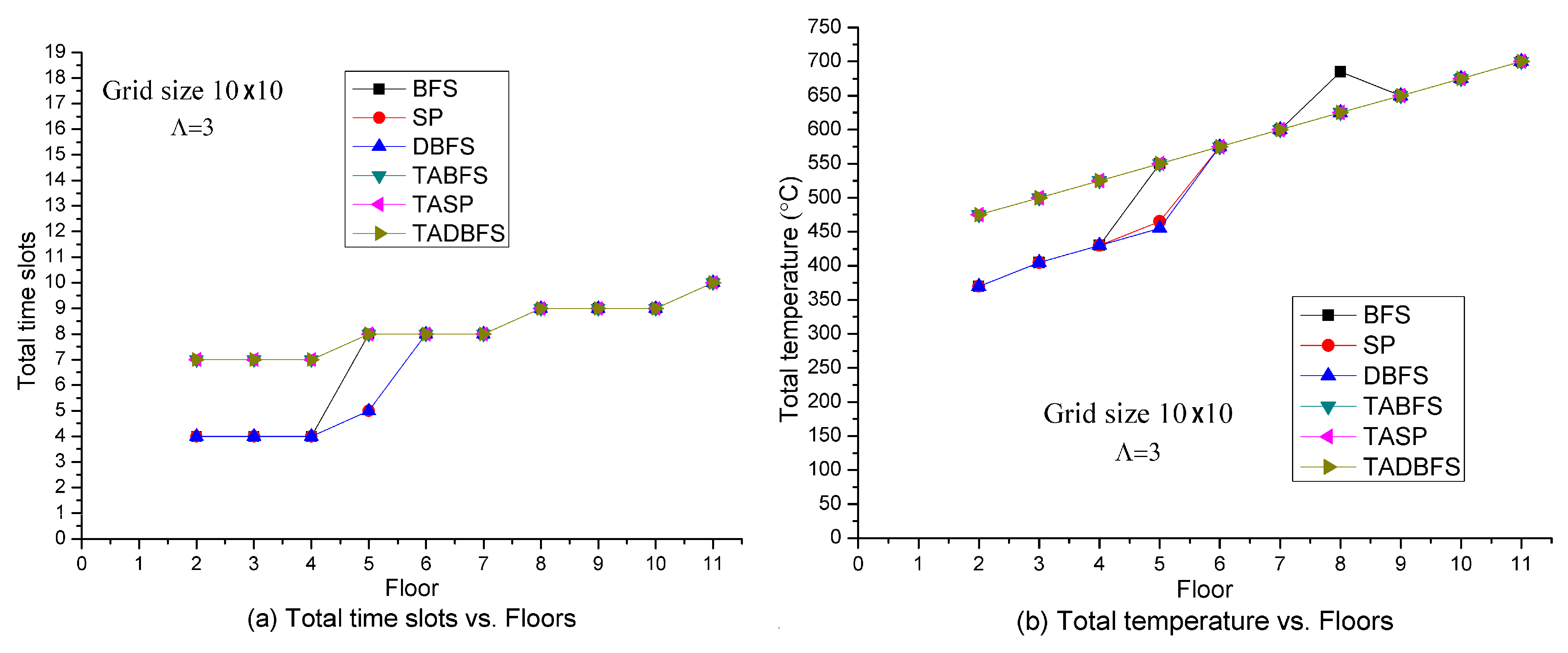
Figure 3 shows the solution quality of these six algorithms in terms of the total number of time slots and total temperature with respect to the number of floors in the open space building. Note that the initial position of the people is at the upper left node on the highest floor. Since the three safe exits are located on the first floor, the total number of time slots and total temperature needed for the people to evacuate is an increasing function with respect to the number of floors in the building. When the objective function is to minimize the total number of time slots on the evacuation path, the algorithms are to evacuate the people as fast as possible. The results are shown in
Figure 3a. In
Figure 3b, we set the cost to be the node’s temperature. With this setting, to minimize the total cost on the evacuation path is to minimize the total temperature on the evacuation path. In other words, the objective is to identify an evacuation path with the lowest temperature.
In
Figure 3a, we observe that SP, BFS and DBFS algorithms direct the evacuation path to emergency exit
Ea in
Figure 2 so that the evacuee can evacuate within four time slots when at the lower floor (
). On the other hand, TASP, TABFS and TADBFS need seven time slots to evacuate because the evacuation path directs to emergency exit
Eb due to the human’s temperature limit constraint in constraint (21). Similarly, we also observe that the total temperature on the evacuation path for SP, BFS and DBFS are much lower than the total temperature on the evacuation path for TASP, TABFS and TADBFS when the number of floors is less than five in
Figure 3b. In
Figure 3a,b, we also observe that TASP, TABFS and TADBFS have the same evacuation time slots and temperature on the evacuation path.
Figure 4 shows the solution quality of these six algorithms with respect to the number of hops in one time slot (i.e.,
). The larger value of
, the larger the hop distance evacuee, can move in one time slot. Because the fire spreads one hop in four directions in one time slot, the larger value of
the faster the evacuation speed. It can be expected that the faster evacuation speed will have a smaller number of time slots and total temperature on the evacuation path. The above argument is justified in
Figure 4, where the total number of time slots and total temperature on the evacuation path is a decreasing function with respect to
. In
Figure 4a,b, we observe that TABFS, TASP and TADBFS cannot identify a feasible solution when
. When
, the fire spreading speed is faster than the evacuation speed, and the temperature at the exits are all higher than the human’s temperature limit. In
Figure 4, we also observe that TABFS, TASP and TADBFS all identify the same evacuation path.
Figure 5 shows the solution quality of these six algorithms with respect to the grid size. Grid size indicates how many temperature sensors are deployed on each floor. For example, there are 144 temperature sensors deployed at each floor in a 12
12 grid size. Increasing the grid size also increases the sensor density. By fixing
, we can expect that an evacuee needs more evacuation time at a large grid size. Hence, the total number of time slots and total temperature on the evacuation path is an increasing function with respect to the grid size. In
Figure 5a,b, we observe that TABFS, TASP and TADBFS all identify the same evacuation path in different sensor density settings. BFS, SP and DBFS identify slightly lower total time slots and total temperature than the TABFS, TASP and TADBFS when the grid size is less than 8
8. This shows that human’s temperature limit constraint-in-constraint (21) plays an un-negligible role in determining the evacuation path for TABFS, TASP and TADBFS.
Based on the results in
Figure 3,
Figure 4 and
Figure 5, we conclude that TABFS and TASP and TADBFS identify the same evacuation path in the open space building. In the following, we test the solution quality in the building with walking paths and walls. We choose the three-story Taipei 101 Shopping Mall as the network because it is one of the most famous buildings in the world.
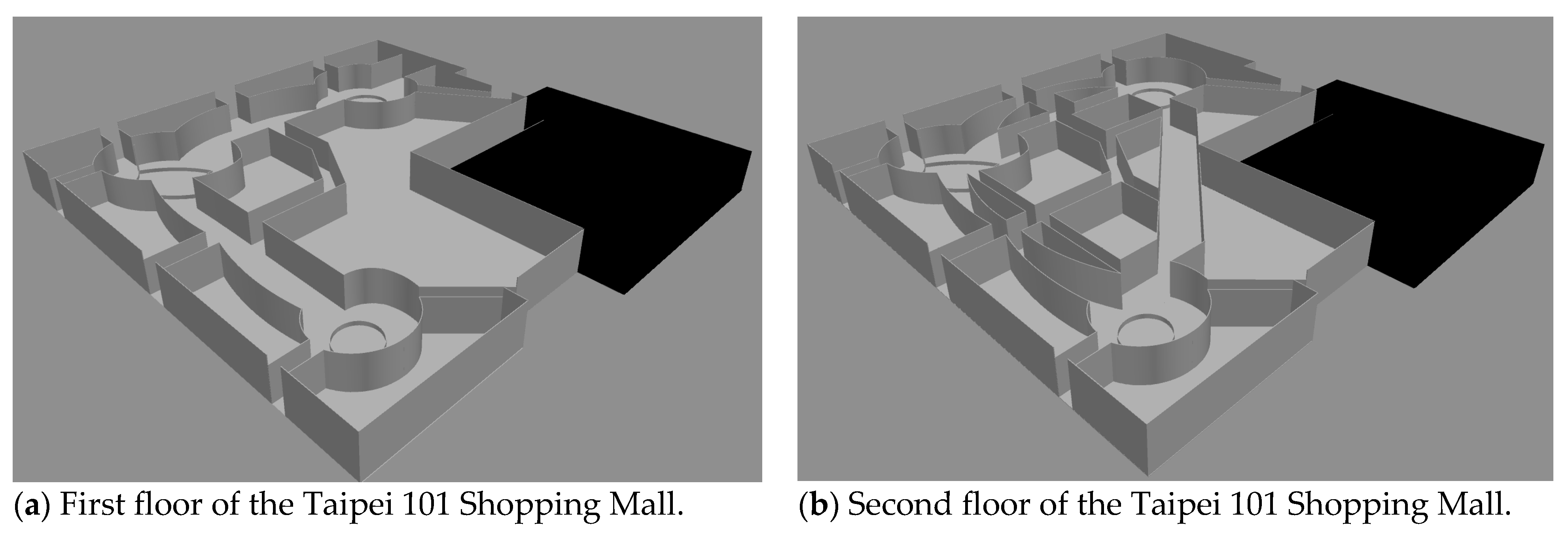
Figure 6 shows the floor plan in the Taipei 101 Shopping Mall. The floor plan on the third floor, which is not shown in
Figure 6, is the same as the first floor. In this three-story shopping mall, there are eight emergency exits on each floor, and there is a staircase connecting every emergency exit between the upper floor and the lower floor.
To capture the walls and walking paths at the Taipei 101 Shopping Mall, a graph mapping scheme in
Section 3 is performed to transform the three-dimensional multi-floor building into a two-dimensional graph. The wall is depicted as a sensor node with a very high-temperature so that people cannot go through the planar graph. Note that the graph mapping scheme from the three-dimension building in
Section 3 determines the structure of the two-dimension graph. Based on the layout of the three-dimension building and graph mapping scheme, the layout of the two-dimension graph can be any structure. Even though the two-dimension graph is a grid structure in the following computational experiments, the proposed algorithms in
Section 4 can tackle any irregular two-dimension graph which is transformed from the three-dimension building.
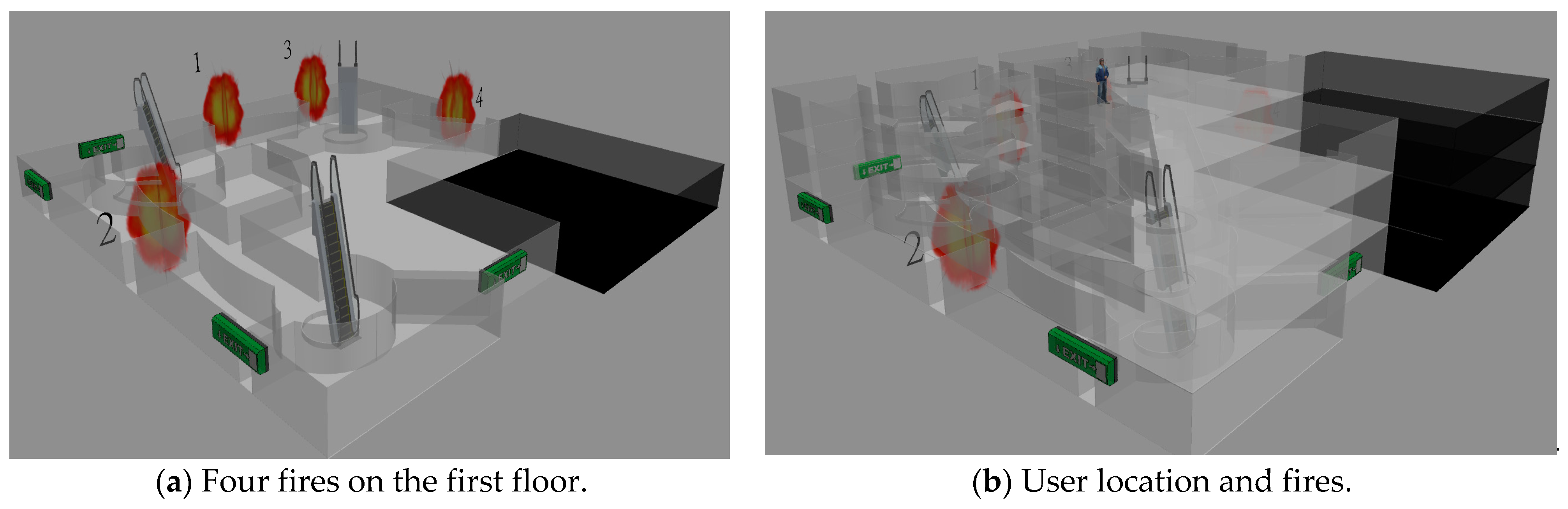
We first test the case when there are four fires on the first floor in the Taipei 101 Shopping Mall. These four fires are located at the four emergency exits on the first floor, which is shown in
Figure 7a. The reason why we test four fires is that there are eight emergency exits; we want to test the solution quality of these six algorithms when half of the exits are on fire. The starting position of the evacuee is at the center on the third floor, which is shown in
Figure 7b. At the first time slot, there are two fires at emergency exits 1 and 2. At the second time slot, there are two fires at emergency exits 3 and 4.
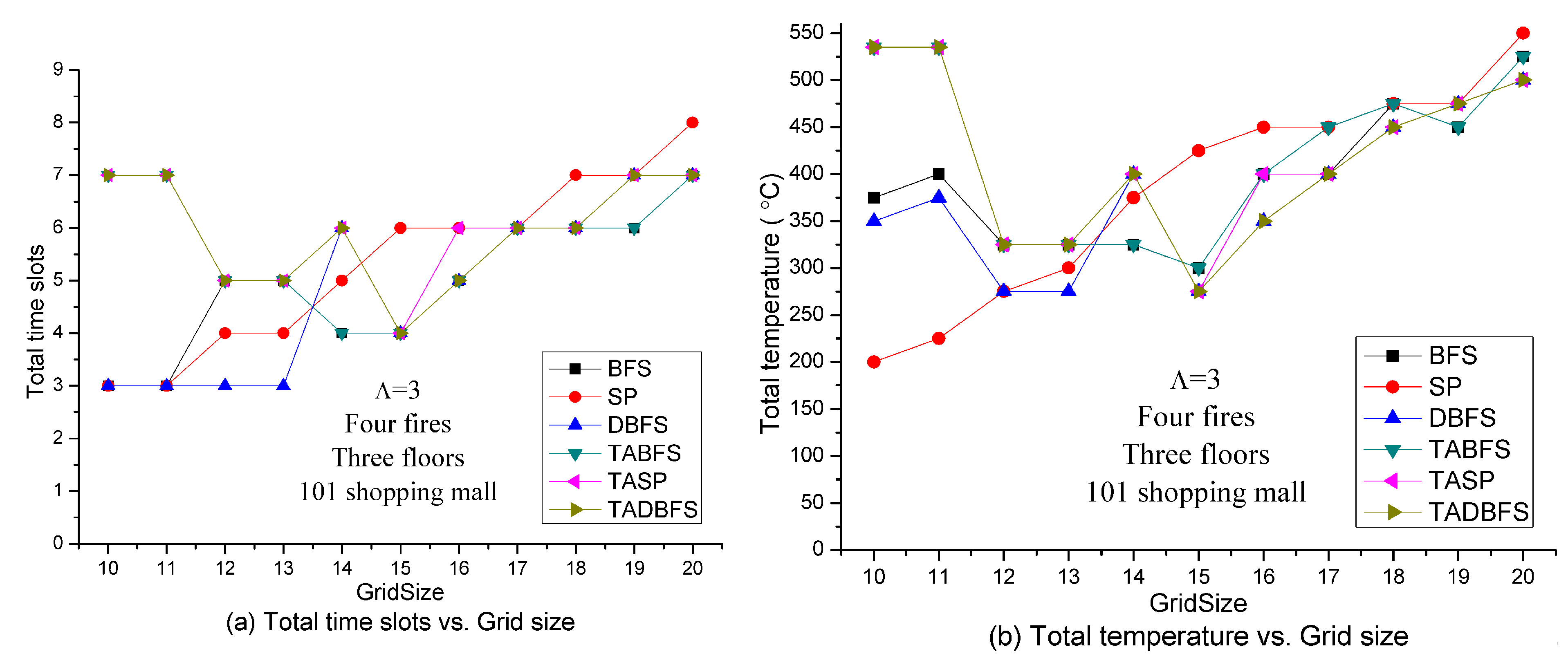
Figure 8 shows the solution quality of these six algorithms with respect to the grid size. Like the experiments in
Figure 5, we can expect the total number of time slots and total temperature needed for the evacuee to evacuate is an increasing function with respect to the grid size. However, there is an interesting result for TASP and TABFS in
Figure 8. Grid size 15
15 has the best results, both in terms of total time slots and total temperature, for TASP, TABFS and TADBFS in
Figure 8a,b. The lowest sensor density at grid size 10
10 and highest sensor density at grid size 20
20 have poor results, both in terms of total time slots and total temperature, for TASP, TABFS and TADBFS in
Figure 8a,b. The results are like a U shape for TASP, TABFS and TADBFS in
Figure 8a,b. In the next experiments, we want to test if this result holds seven fires.
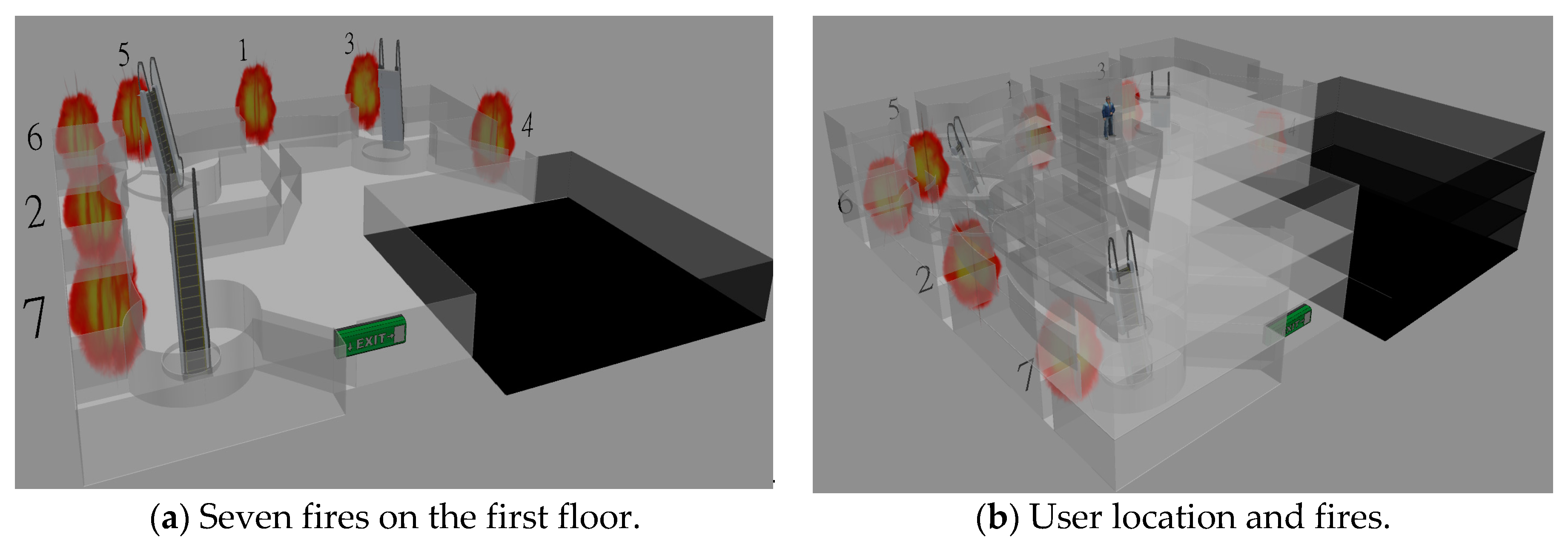
In the next tested case, we consider there are seven fires on the first floor in the Taipei 101 Shopping Mall. These seven fires are exacted located at the seven emergency exits on the first floor, and there is only one emergency exit that does not have a fire, as shown in
Figure 9a. The starting position of people is at the center on the third floor, which is shown in
Figure 9b. At the first time slot, there are two fires at emergency exits 1 and 2. At the second time slot, there are two fires at emergency exits 3 and 4. At the third time slot, there are two fires at emergency exits 5 and 6. At the fourth time slot, there is one fire at emergency exit 7. Then, there is only one safe emergency exit left for evacuation.
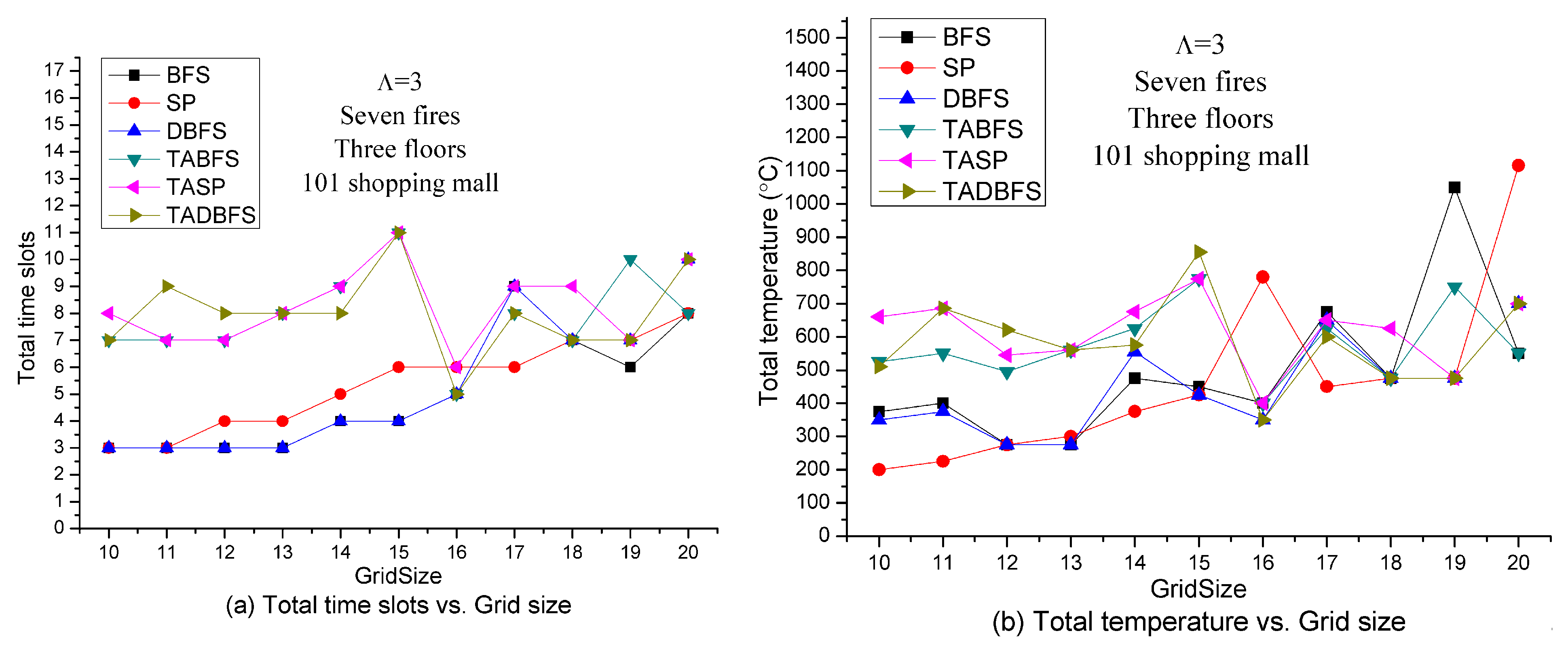
Figure 10 shows the solution quality of these six algorithms with respect to the grid size. Like the results in
Figure 8, we also observe a U shape for TASP, TABFS, and TABFS in
Figure 10a,b where the best sensor density is at grid size 16
16 in terms of time slots and total temperature on the evacuation path. In other words, too low or too high sensor density will increase the evacuation time and temperature on the evacuation path. These results show that the proposed algorithms (TASP, TABFS and TABFS) can help to determine the best temperature sensor deployment density in the Taipei 101 Shopping Mall in considering the evacuee’s evacuation time and evacuation cost.
Based on the sensor deployment density experiments in
Figure 8 and
Figure 10, in the next set of experiments, we set the sensor density to be grid size 15
15.
Figure 11 shows the solution quality comparisons with respect to the number of fires on the emergency exits. It can be expected that the larger number of fires, the lesser number of available emergency exits for evacuation. Because BFS, SP and DBFS do not address the constraint (21), the results are all the same regardless of the number of fires. On the other hand, the solution space for TABFS, TASP and TADBFS becomes smaller when increasing the number of fires on the emergency exit. These three algorithms get almost the same results in evacuation time slots. However, TASP and TADBFS can get better results than TABFS in total temperature on the evacuation path when the number of fires is less than seven. When there are seven fires, TABFS and TASP identify a more comfortable (i.e., lower total temperature) evacuation path than TADBFS.
Figure 12 shows the solution quality comparisons with respect to the number of hops in one time slot in seven fires and 15
15 grid size. Because the grid size is fixed and the number of fires is also fixed, increasing the value of
indicates increasing the evacuation speed. It can be expected that increasing the evacuation speed can increase the success probability of evacuation. Hence, evacuation time and total temperature on the evacuation path should be a decreasing function with respect to the value of
. The results in
Figure 12 justify the above argument. TABFS, TASP and TADBFS get the same results in total time slots in different values of
. However, TASP and TADBFS can get a little bit better results than TABFS in terms of total temperature on the evacuation path when
. When
, TASP and TABFS can get better results than TADBFS in terms of total temperature on the evacuation path.
In the above experiments, the solution quality comparison between these six algorithms is examined for a single evacuee. In the next experiments, we test the solution quality of six algorithms for a group of evacuees. One difference between evacuating a single evacuee and evacuating a large number of people in the evacuation capability in one time slot. The other difference is the computational time of the evacuation algorithm is required to be faster than the fire spreading speed when evacuating a group of people. In
Figure 13, we compare the solution quality in terms of evacuation capacity and evacuation speed in the Taipei 101 Shopping Mall. Here, we also set the sensor density to be grid size 15
15 on each floor. When evacuating a group of people, the number of people who can pass through an emergency exit at each time slot is limited by the evacuation capability. In the following experiments, we set at most thirty evacuees that can pass through an emergency exit in one time slot. Hence, if more than thirty evacuees evacuate at the same emergency exit at the same time slot, then only 30 evacuees can be evacuated, and the other evacuees should wait to be evacuated at the next time slot.
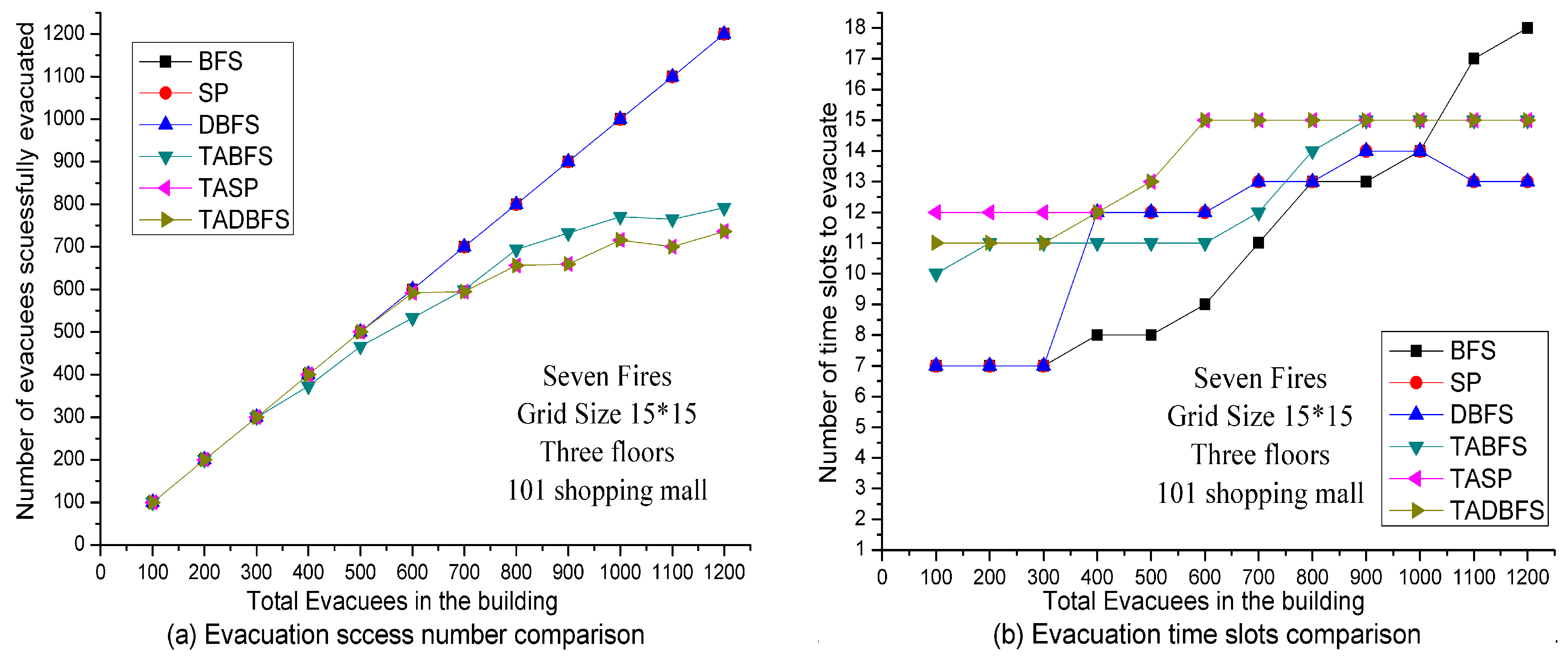
In
Figure 13a, the number of evacuees successfully evacuated is compared between these six algorithms. Because BFS, SP and DBFS do not address the human’s temperature limit constraint in constraint (21), all the evacuees in the building can be evacuated eventually. Hence, the number of evacuees successfully evacuated is the same as the number of evacuees in the building. On the other hand, the number of evacuees successfully evacuated is less than or equal to the number of evacuees in the building for TABFS, TASP and TADBFS algorithms because of human’s temperature limit constraint in Constraint (21). Interestingly, we observe that TASP and TADBFS have the same number of evacuees successfully evacuated. TASP and TADBFS have slightly better results than TABFS when the number of evacuees in the building is less than 700. However, TABFS has slightly better results when the number of evacuees in the building is greater than 700.
In
Figure 13b, we show the number of time slots needed to evacuate the evacuees. To be more specific, the evacuation speed is compared to these six algorithms. We observe that TABFS can evacuate faster than TASP and TADBFS when the number of evacuees in the building is less than 900. After 900, the number of time slots to evacuate is all 15 for these three algorithms. This indicates that all the emergency exits are on fire after 15 time slots. Based on reports of fire progression rapidly in minutes in [1, 3], we set the duration of one time slot is one minute. Then the golden window for evacuation is 15 min when considering the extreme case of 7 fires. Then, the computational time of the evacuation algorithm is required to be faster than the fire spreading speed when evacuating a group of people. We perform the computational experiments in the computer with a 3.0 GHz AMD Ayzen 7 1700 Eight-core processor with 16 GB RAM. When evacuating 1200 evacuees, the computational time for TABFS and TADBFS are all about ten minutes, and the computational time for TASP is about four hours, which justifies the computational complexity results in
Section 5.2. Then only TABFS and TADBFS are the candidate evacuation algorithms. In considering the computational time and group evacuation results in
Figure 13, we conclude that TADBFS should be chosen as the evacuation algorithm when the number of evacuees to be evacuated is less than 700. When the number of evacuees to be evacuated is greater than 700, TABFS is recommended to be adopted as the evacuation algorithm.


