Reliable Road Scene Interpretation Based on ITOM with the Integrated Fusion of Vehicle and Lane Tracker in Dense Traffic Situation


Abstract
:1. Introduction
- The state-of-the-art research regarding multi-lane detection focuses on a variety of challenging multi-lane detection scenarios. However, there is a lack of intense research on multi-lane detection and tracking regarding complex road environments for the situational awareness of AD applications. We define three bad influential factors, which are the presence of traffic, road markers, and shadowy road conditions for the four-lane tracker. To overcome this problem, we propose a novel framework for the lane-tracker method integrated with a vehicle tracker consisting of a camera and a radar.
- To assure the robustness of the proposed method to extract lane candidate features, we present two main contributions to the framework for multi-lane tracking. The first is to remove those two key influential factors with the integration of the vehicle tracker and the multi-lane tracker through the ITOM we have introduced. The other is to enhance the performance of the algorithm for extracting lane candidate features in the case of shadowy conditions through a frame level detection approach.
- To assure consistency for the states with multi-lanes, a method for frame-level management of multi-lane detection and tracking is introduced. For multi-lane detection, we design a specified feature extraction function and present a method to select the right feature among the lane candidate features in the current frame. Finally, the states of the multi-lane scenario are framed in a managed condition that it can adjust parameter changes and manage the lane track histories for the multi-lane tracker.
2. Related Work
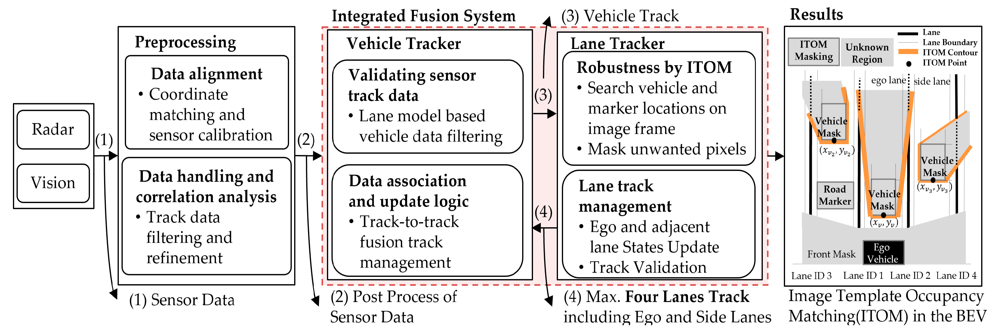
3. System Overview
3.1. Multi-Sensor Data Fusion Framework
- The transformation from each sensor frame to the vehicle local frame:
- Typical installation positions of the camera and radar sensor:
- Image transformationThe camera intrinsic parameters ( and extrinsic parameters (: rotation,: Translation matrix) are obtained from the process of the camera calibration in Figure 2d.
3.2. Experimental Setup
- A 76-77GHz (174 m, +/−10°) and mid-range (60 m, +/−45°) delphi-ESR1.1 radar provides simultaneous multimode electronic scanning simultaneously. However, we are only concerned with the object’s range , azimuth , and speed data up to 64 targets within the region of interest of the extent of the image frame (35 m).
- A Mobileye 630 vision module detects and tracks four-lane and vehicle positions up to 64 target tracks with a horizontal FOV of . We take object position track for the sake of facile fusion with the radar track instead of vehicle detection from the image frame. Furthermore, we can easily compare four-lane tracks with our integrated lane tracker method.
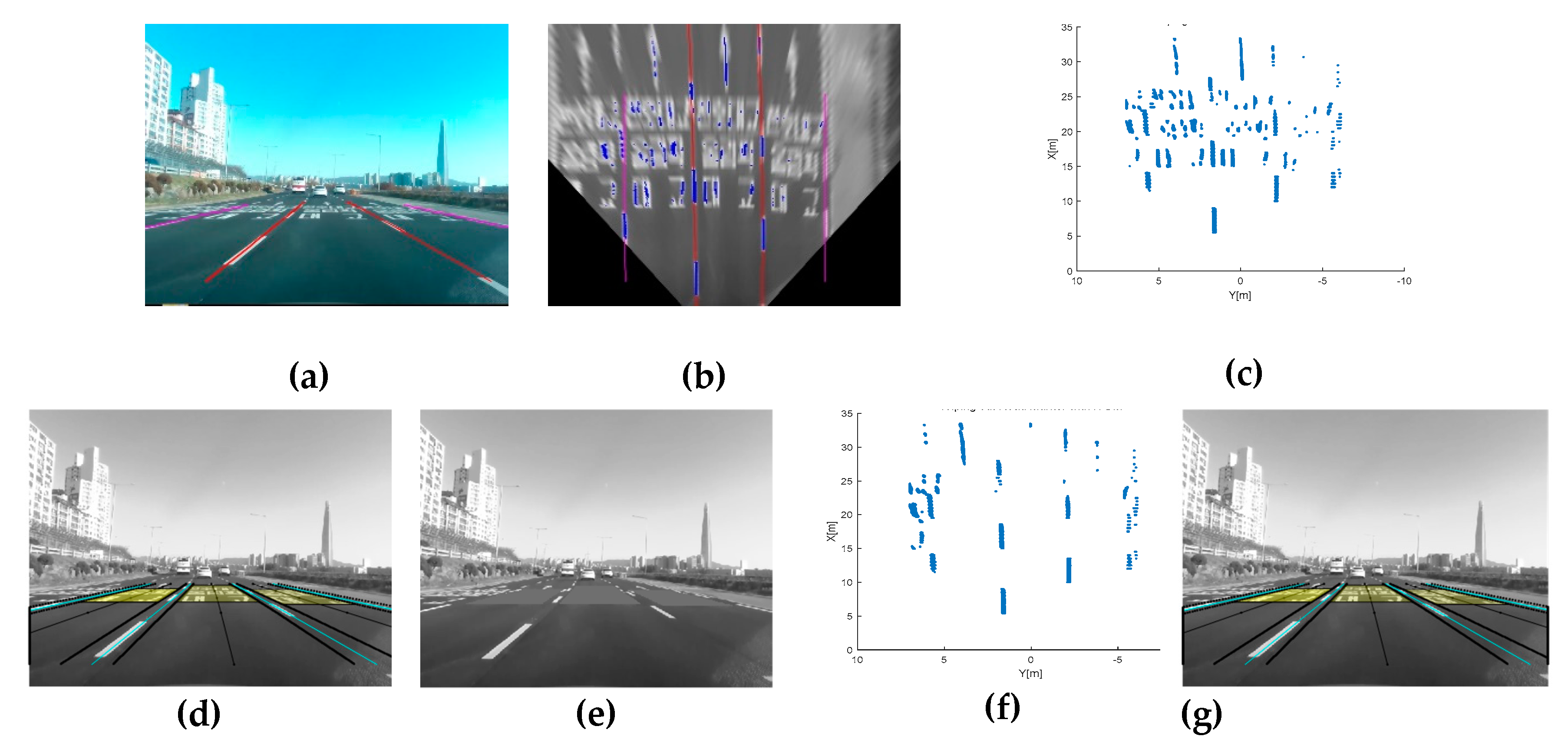
- A RealSense SR-300 camera offers 1920 × 1080 pixels with a horizontal FOV of 73°, with which we interpret and understand the road scene. We have downsized the image by 640 × 480 pixels for improving computational efficiency with performing appropriate performance for the situational awareness. The image frames are mainly used for multi-lane detection and integration with the vehicle tracker. The feature points in the vehicle coordinates are derived from the rectified top-view image frame as described in Section 3.1.
4. Integrated Fusion of the Vehicle and Lane Tracker
4.1. Vehicle Tracker
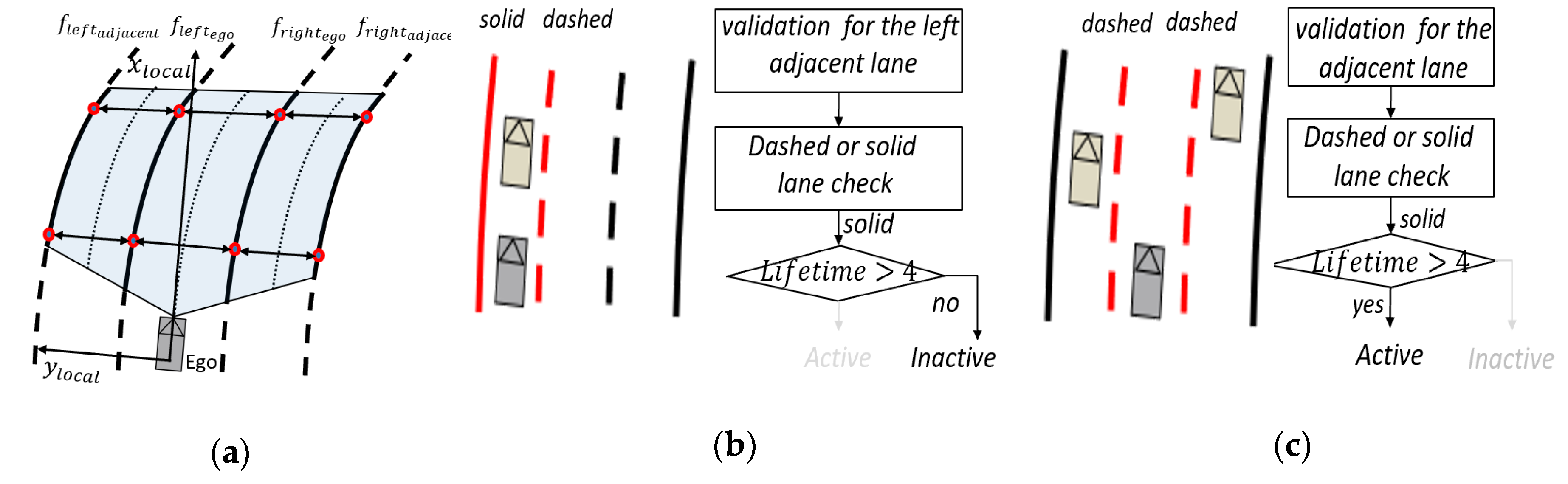
4.2. Lane Tracker
4.2.1. Frame Level Multi-Lane Detection and Tracking
4.2.2. Robustness under Complex Road Conditions
5. Experimental Results
5.1. Experimental Methodology
5.2. Experimental Results
6. Conclusions
Author Contributions
Funding
Acknowledgments
Conflicts of Interest
References
- Euro NCAP. Available online: https://www.euroncap.com/en/for-engineers/protocols/safety-assist/ (accessed on 16 October 2019).
- SAE International. Taxonomy and Definitions for Terms Related to Driving Automation Systems for on-Road Motor Vehicles; SAE International: Warrendale, PA, USA, 2018. [Google Scholar]
- Louw, T.; Merat, N.; Jamson, H. Engaging with highly automated driving: To be or not to be in the loop? In Proceedings of the Eighth International Driving Symposium on Human Factors in Driver Assessment, Training, and Vehicle Design, Salt Lake City, UT, USA, 22–25 June 2015. [Google Scholar]
- Zhou, H.; Zhang, H.D.; Hasith, K.; Wang, H. Real-time Robust Multi-lane Detection and Tracking in Challenging Urban Scenarios. In Proceedings of the 2019 IEEE 4th International Conference on Advanced Robotics and Mechatronics (ICARM), Osaka, Japan, 3–5 July 2019; pp. 936–941. [Google Scholar]
- Hur, J.; Kang, S.N.; Seo, S.W. Multi-Lane Detection in Urban Driving Environments Using Conditional Random Fields. In Proceedings of the 2013 IEEE Intelligent Vehicles Symposium (IV), Gold Coast, Australia, 23–26 June 2013; pp. 1297–1302. [Google Scholar]
- Xuan, H.; Liu, H.Z.; Yuan, J.Z.; Li, Q. Robust Lane-Mark Extraction for Autonomous Driving under Complex Real Conditions. IEEE Access 2017, 6, 5749–5765. [Google Scholar] [CrossRef]
- Kang, S.N.; Lee, S.; Hur, J.; Seo, S.W. Multi-Lane Detection Based on Accurate Geometric Lane Estimation in Highway Scenarios. In Proceedings of the IEEE Intelligent Vehicles Symposium Proceedings, Dearborn, MI, USA, 8–11 June 2014; pp. 221–226. [Google Scholar]
- Deusch, H.; Jürgen, W.; Stephan, R.; Magdalena, S.; Marcus, K.; Klaus, D. A Random Finite Set Approach to Multiple Lane Detection. In Proceedings of the 2012 15th International IEEE Conference on Intelligent Transportation Systems, Anchorage, AK, USA, 16–19 September 2012; pp. 270–275. [Google Scholar]
- Zhao, K.; Mirko, M.; Christian, N.; Dennis, M.; Stefan, M.S.; Josef, P. A Novel Multi-Lane Detection and Tracking System. In Proceedings of the IEEE Intelligent Vehicles Symposium, Alcala de Henares, Spain, 3–7 June 2012; pp. 1084–1089. [Google Scholar]
- Nieto, M.; Salgado, L.; Jaureguizar, F.; Arróspide, J. Robust multiple lane road modeling based on perspective analysis. In Proceedings of the 15th IEEE International Conference on Image Processing, San Diego, CA, USA, 12–15 October 2008; pp. 2396–2399. [Google Scholar]
- Vacek, S.; Bergmann, S.; Mohr, U.; Dillmann, R. Rule-based tracking of multiple lanes using particle filters. In Proceedings of the 2006 IEEE International Conference on Multisensor Fusion and Integration for Intelligent Systems, Heidelberg, Germany, 3–6 September 2006; pp. 203–208. [Google Scholar]
- Meuter, M.; Stefan, M.S.; Adalbert, M.; Stephanie, H.; Christian, N.; Anton, K. A Novel Approach to Lane Detection and Tracking. In Proceedings of the 12th International IEEE Conference on Intelligent Transportation Systems, St. Louis, MO, USA, 3–7 October2009; pp. 582–587. [Google Scholar]
- Minchae, L.; Chulhoon, J.; Myoungho, S. Probabilistic Lane Detection and Lane Tracking for Autonomous Vehicles Using a Cascade Particle Filter. Proc. Inst. Mech. Eng. Part D J. Automob. Eng. 2015, 229, 1656–1671. [Google Scholar]
- Sehestedt, S.A.; Sarath, K.; Alen, A.; Gamini, D. Efficient Lane Detection and Tracking in Urban Environments. In Proceedings of the European Conference on Mobile Robots: ECMR, Freiburg, Germany, 19–21 September 2007; pp. 19–21. [Google Scholar]
- Haloi, M.; Dinesh, B.J. A robust lane detection and departure warning system. In Proceedings of the IEEE Intelligent Vehicles Symposium (IV), Seoul, Korea, 28 June–1 July 2015; pp. 126–131. [Google Scholar]
- Kim, Z.W. Robust lane detection and tracking in challenging scenarios. IEEE Trans. Intell. Transp. Syst. 2008, 9, 16–26. [Google Scholar] [CrossRef] [Green Version]
- Tapia-Espinoza, R.; Torres-Torriti, M. Robust lane sensing and departure warning under shadows and occlusions. Sensors 2013, 13, 3270–3298. [Google Scholar] [CrossRef] [PubMed] [Green Version]
- John, V.; Liu, Z.; Mita, S.; Guo, C.; Kidono, K. Real-time road surface and semantic lane estimation using deep features. Signal. Image Video Process. 2018, 12, 1133–1140. [Google Scholar] [CrossRef]
- Southall, B.; Camillo, J.T. Stochastic Road Shape Estimation. In Proceedings of the Eighth IEEE International Conference on Computer Vision (ICCV 2001), Vancouver, BC, Canada, 7–14 July 2001; pp. 205–212. [Google Scholar]
- Danescu, R.; Sergiu, N. Probabilistic Lane Tracking in Difficult Road Scenarios Using Stereovision. IEEE Trans. Intell. Transp. Syst. 2009, 10, 272–282. [Google Scholar] [CrossRef]
- Zhang, W.; Liu, H.; Wu, X.; Xiao, L.; Qian, Y.; Fang, Z. Lane marking detection and classification with combined deep neural network for driver assistance. Proc. Inst. Mech. Eng. Part D J. Automob. Eng. 2019, 233, 1259–1268. [Google Scholar] [CrossRef]
- Bakr, M.A.; Lee, S. Distributed multisensor data fusion under unknown correlation and data inconsistency. Sensors 2017, 17, 2472. [Google Scholar] [CrossRef] [PubMed] [Green Version]
- Chavez-Garcia, R.O.; Aycard, O. Multiple sensor fusion and classification for moving object detection and tracking. IEEE Trans. Intell. Transp. Syst. 2015, 17, 525–534. [Google Scholar] [CrossRef] [Green Version]
- Matzka, S.; Richard, A. A comparison of track-to-track fusion algorithms for automotive sensor fusion. In Multisensor Fusion and Integration for Intelligent Systems; Springer: Berlin/Heidelberg, Germany, 2009; pp. 69–81. [Google Scholar]
- Stiller, C.; Fernando, P.L.; Marco, K. Information fusion for automotive applications–An overview. Inf. Fusion 2011, 12, 244–252. [Google Scholar] [CrossRef]
- Yu, Z.; Bai, J.; Chen, S.; Huang, L.; Bi, X. Camera-Radar Data Fusion for Target Detection via Kalman Filter and Bayesian Estimation (No. 2018-01-1608). In SAE Technical Paper, Proceedings of the Intelligent and Connected Vehicles Symposium, Kunshan City, China, 14–15 August 2018; SAE International: Warrendale, PA, USA, 2018; pp. 1–8. [Google Scholar]
- Dickmanns, E.D.; Mysliwetz, B.D. Recursive 3-d road and relative ego-state recognition. IEEE Trans. Pattern Anal. Mach. Intell. 1992, 2, 199–213. [Google Scholar] [CrossRef]
- Küçükmanisa, A.; Tarım, G.; Urhan, O. Real-time illumination and shadow invariant lane detection on mobile platform. J. Real Time Image Process. 2017, 16, 1–14. [Google Scholar] [CrossRef]
- Torr, P.H.; Zisserman, A. MLESAC: A new robust estimator with application to estimating image geometry. Comput. Vis. Image Underst. 2000, 78, 138–156. [Google Scholar] [CrossRef] [Green Version]


| Research Target Detection Scope | Road Types and Conditions | Strategies and Characteristics |
|---|---|---|
| Single-Lane [12,13,14,15,16,17,18,19,20,21] | Challenge scenarios [13,14,15,16,20] | Particle filter [14,19,20], Kalman [12,16], Robust strategies [15,16,17], Deep learning [18,21] |
| Multi-Lane [4,5,6,7,8,9,10,11] | Challenge scenarios [4,5,6] Adjacent lane [7,8,9,10] | CRF association [4,5], Robust strategies [6,7,10], Particle filter [8,11], Spline EKF [9] |
| Measure | TPR | FPR | ||
|---|---|---|---|---|
| Type | Ego Lane | Adjacent | Total | Total |
| ITOM Lane Tracker | 0.995 | 0.968 | 0.98 | 0.019 |
| Mobileye 630 | 0.914 | 0.886 | 0.9 | 0.1 |
© 2020 by the authors. Licensee MDPI, Basel, Switzerland. This article is an open access article distributed under the terms and conditions of the Creative Commons Attribution (CC BY) license (http://creativecommons.org/licenses/by/4.0/).
Share and Cite
Jeong, J.; Yoon, Y.H.; Park, J.H. Reliable Road Scene Interpretation Based on ITOM with the Integrated Fusion of Vehicle and Lane Tracker in Dense Traffic Situation. Sensors 2020, 20, 2457. https://doi.org/10.3390/s20092457
Jeong J, Yoon YH, Park JH. Reliable Road Scene Interpretation Based on ITOM with the Integrated Fusion of Vehicle and Lane Tracker in Dense Traffic Situation. Sensors. 2020; 20(9):2457. https://doi.org/10.3390/s20092457
Chicago/Turabian StyleJeong, Jinhan, Yook Hyun Yoon, and Jahng Hyon Park. 2020. "Reliable Road Scene Interpretation Based on ITOM with the Integrated Fusion of Vehicle and Lane Tracker in Dense Traffic Situation" Sensors 20, no. 9: 2457. https://doi.org/10.3390/s20092457