In
Figure 1, Snell’s law of refraction is applied at the bottom surface of the lens as follows:
where
η is the independent variable and
n is a refractive index. Also, the following electrical path length condition can be imposed:
where
as discussed in Reference [
1]. Similar to (1), Snell’s law of refraction is applied at the top surface of the lens as follows:
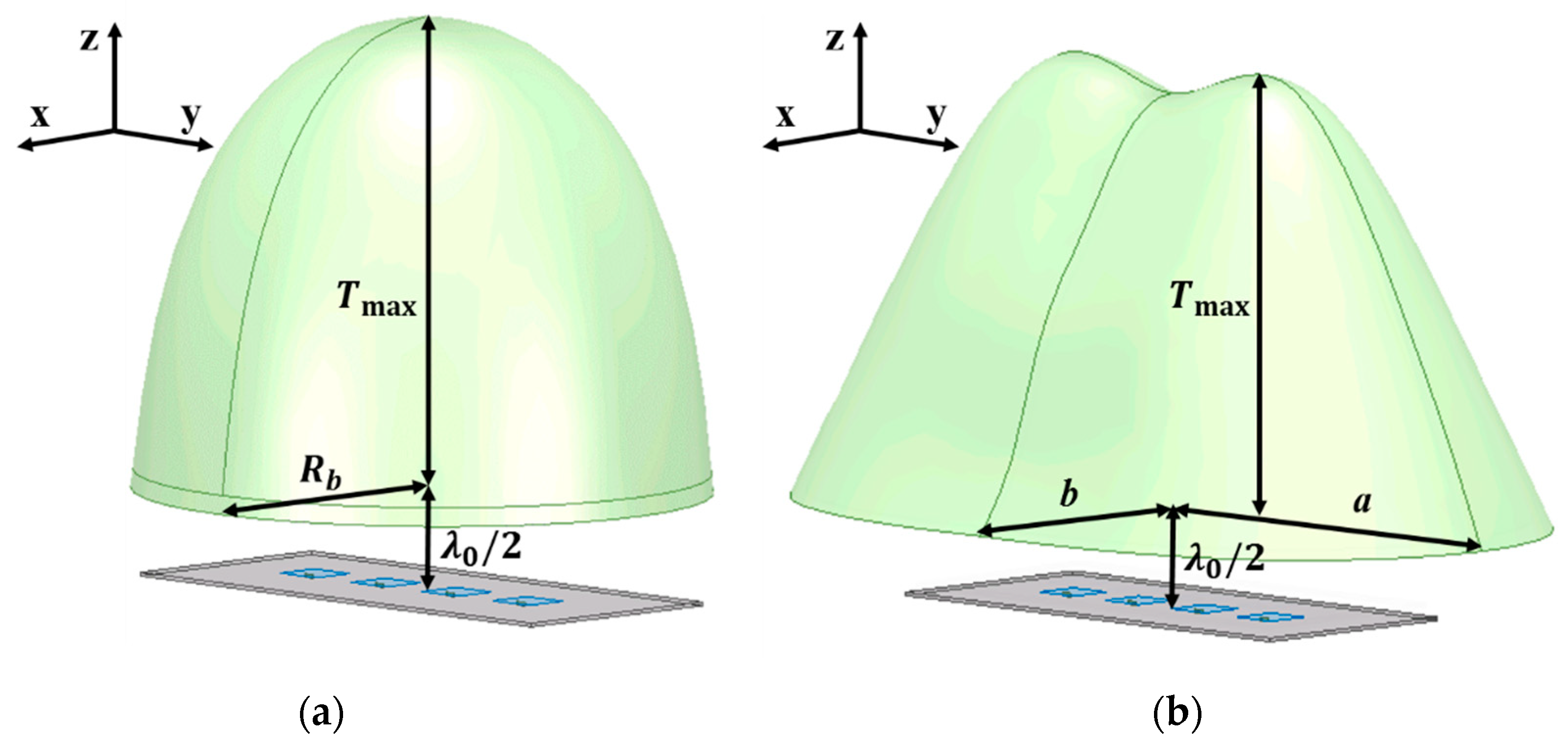
At the beginning of the design procedure,
F and
Tmax are first chosen as input parameters.
F is the distance between the lens and the antenna and
Tmax is the thickness of the thickest part of the dielectric lens. The bottom surface of the lens is selected to be planar as a conventional reference geometry and the upper surface is determined by the simultaneous equations above. The radius at the bottom of the lens,
Rb is determined by the total reflection condition and the corresponding incidence critical angle is given as follows:
where
αc is the ray’s critical incidence angle measured with respect to the local normal vector of the lens,
[
1]. It should be noted that once
F,
Tmax and
n in
Figure 1 are chosen maximum available radius of the lens is decided by the total reflection condition at the top surface of the lens. In more detail, once a design point on the lens is chosen by
η to decide the dielectric thickness at that point,
F,
Tmax,
n and
η become known. Accordingly, other five variables
r,
γ,
l,
α and
s can be solved by five Equations (1)–(5). As
α goes over
αc, reflections on the top surface of the lens goes into the total reflection condition and thus no solutions exist for the five variables related to the lateral size of the lens by
Rb =
r * sin(
ηmax). Therefore, if one want to further increase the lateral size of the dielectric lens, the fixed values for
F,
Tmax and
n must be changed. For example, the increase of
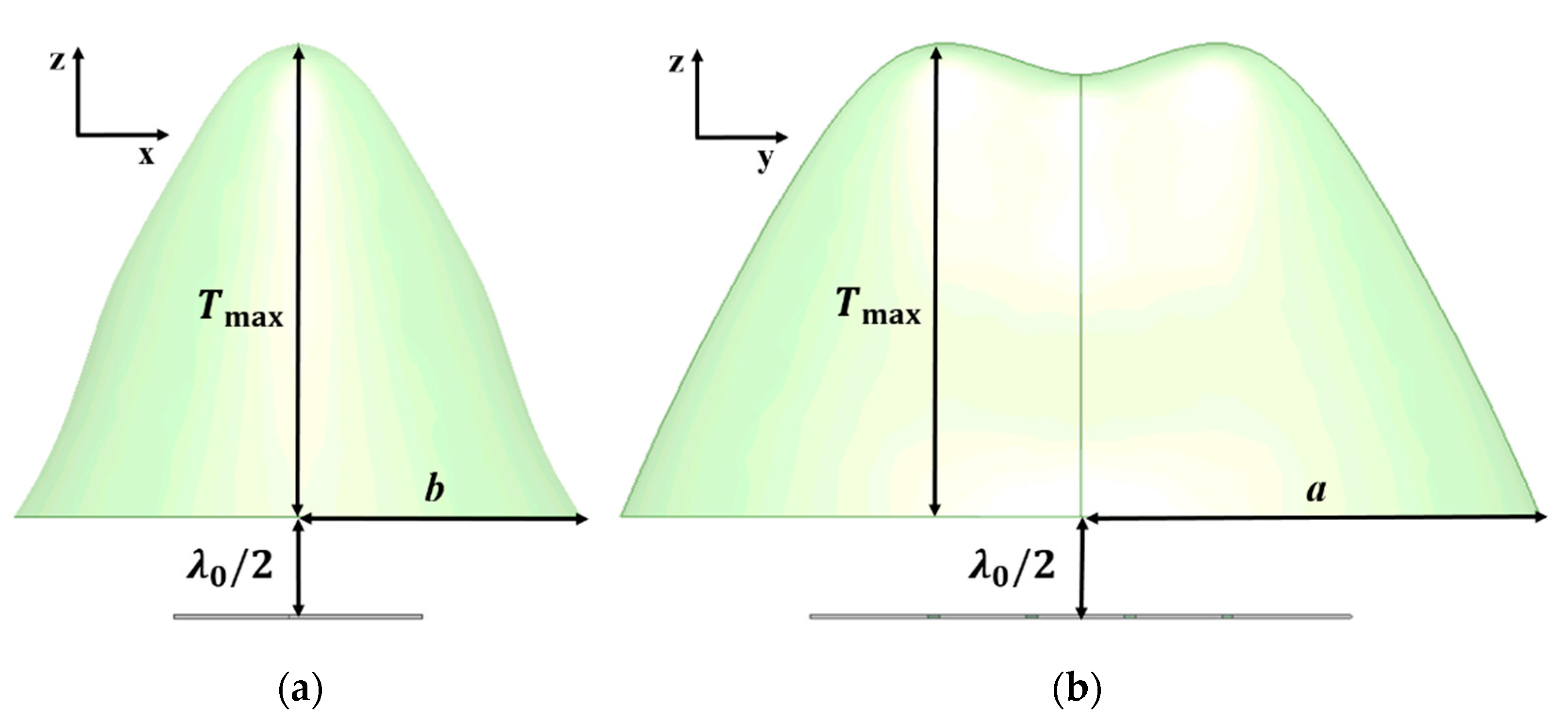
Tmax allows for the increase of the lateral dimension of the lens. Unlike the PE method assuming a point source, HP method that can consider multiple sources practically allows for design of the wider dielectric lens. This is why once
F,
Tmax and
n are fixed for fair comparisons, the lateral dimensions of the two different method-based lenses can be different, suggesting practical advantages of HP method.
Since most antenna applications use antenna arrays due to their beam steering capability, the assumption of a single point source in the above PE method limits the achievement of optimal lens gain for the multiple and arbitrarily arranged radiating sources.


