Directional Modulation Technique Using a Polarization Sensitive Array for Physical Layer Security Enhancement


Abstract
:1. Introduction
1.1. Related Works
1.2. Our Contribution
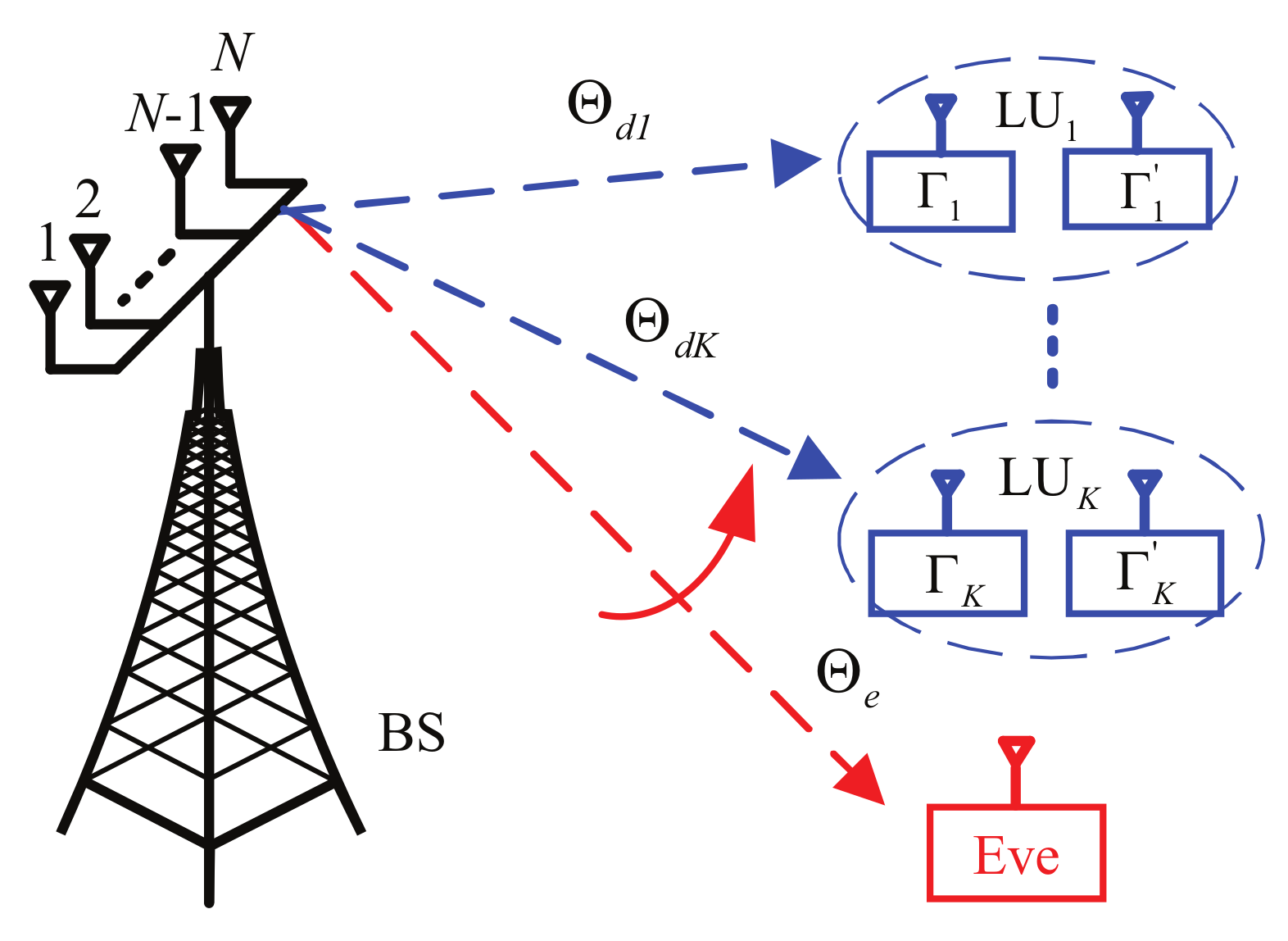
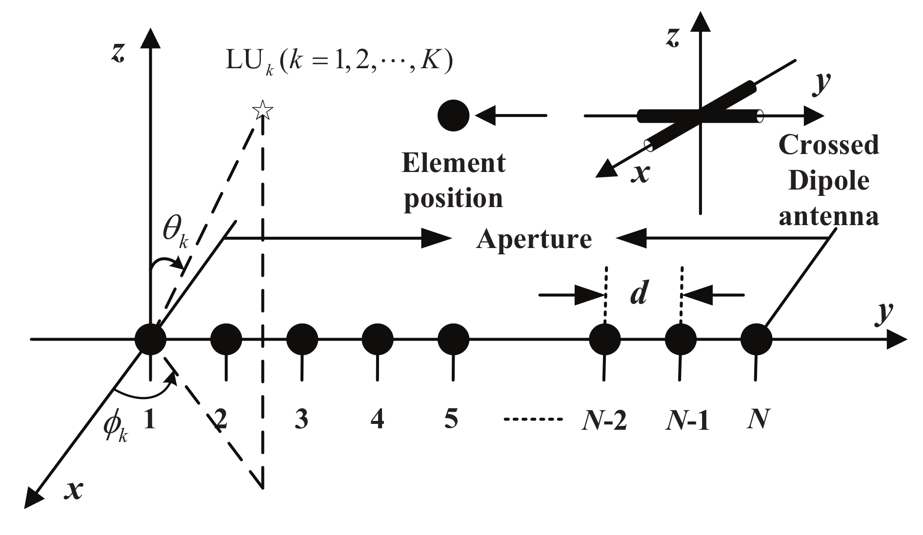
2. System Model
3. Review of Polarized Beamforming
4. Principle of the Proposed Multi-Beam DM Technique Using a PSA
4.1. From a Sampling Perspective
4.2. From a Signal Processing Perspective
5. Security Performance Analysis for the Proposed DM Scheme
5.1. Security Performance Analysis When Eves with Polarization Information
5.2. Security Performance Analysis When Eves without Polarization Information
5.3. Security Performance Analysis from a Signal Processing Perspective
5.4. Metrics
6. Simulations and Discussions
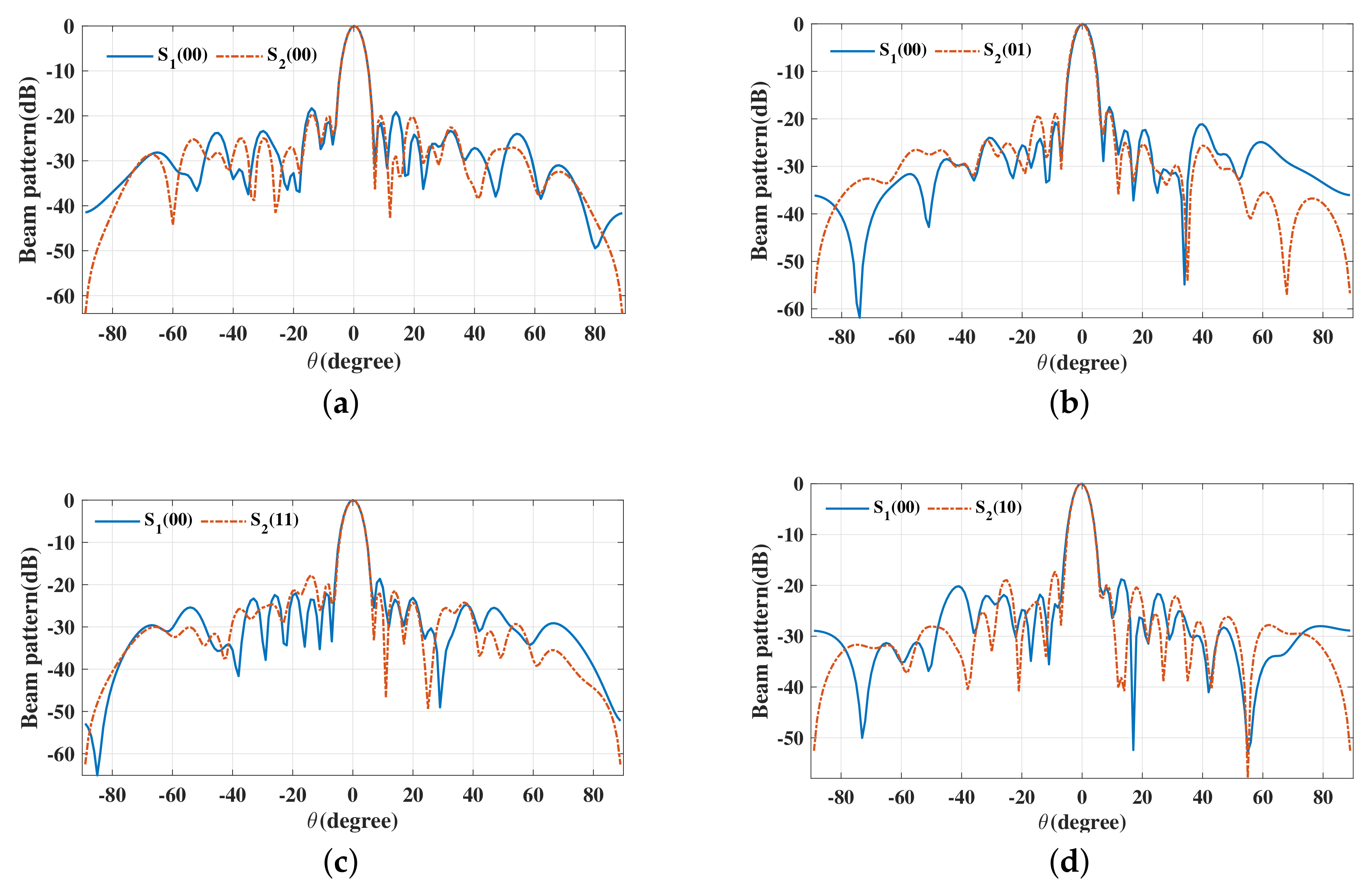
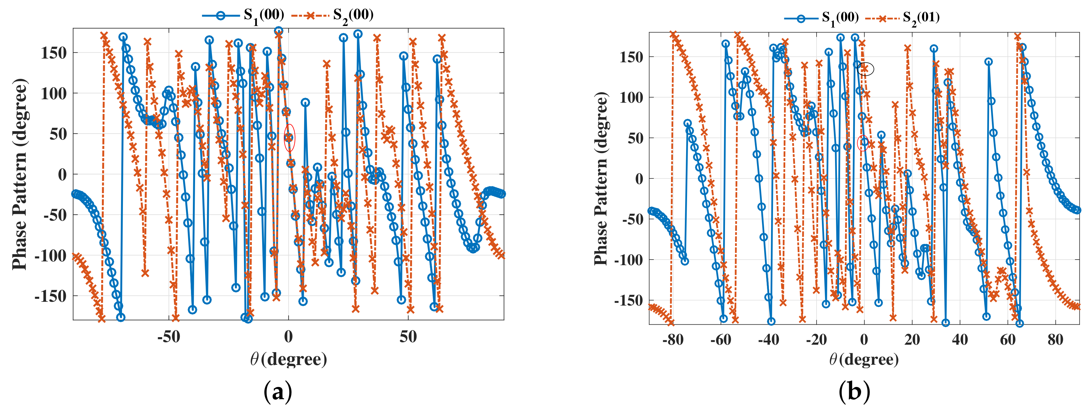
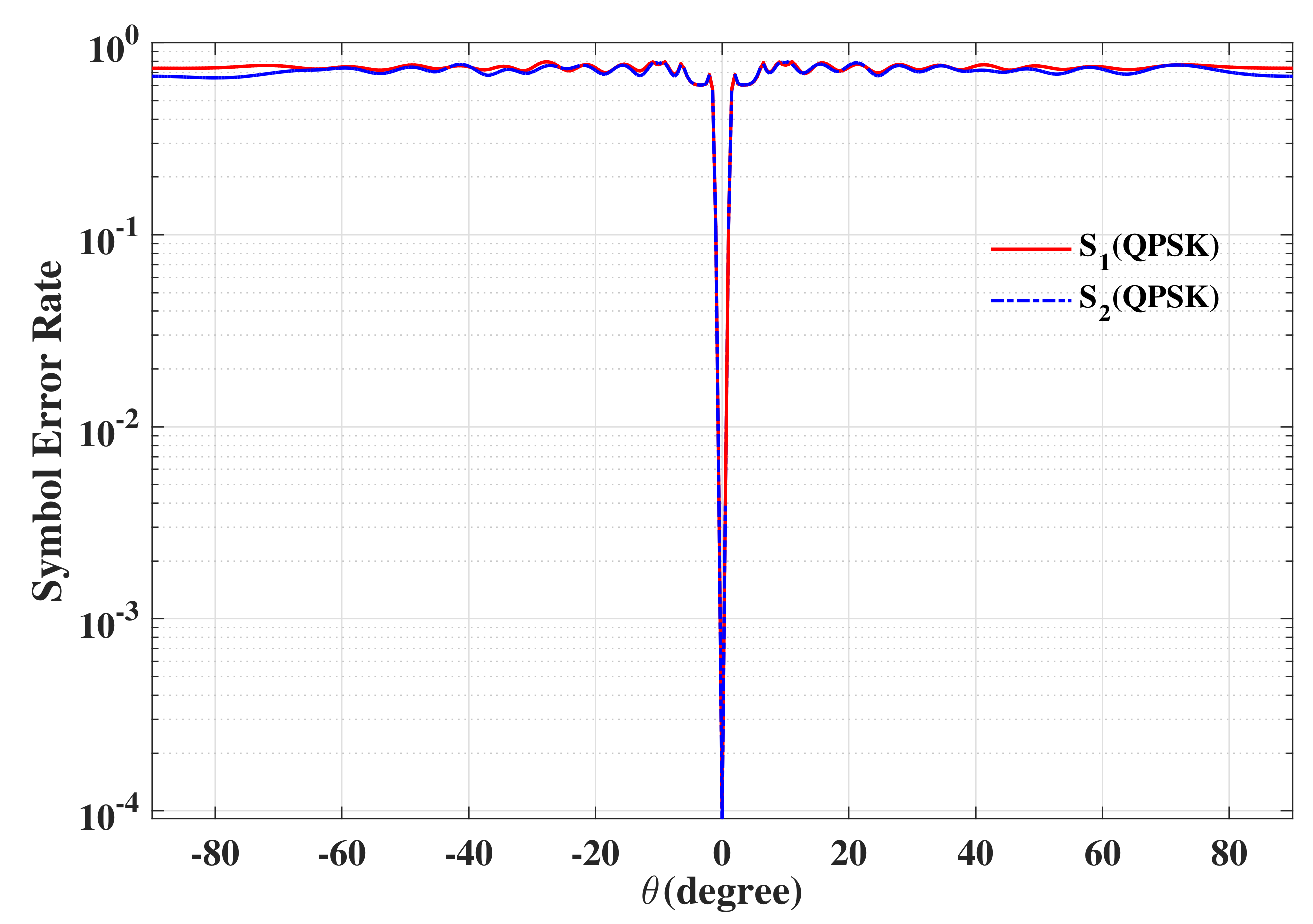
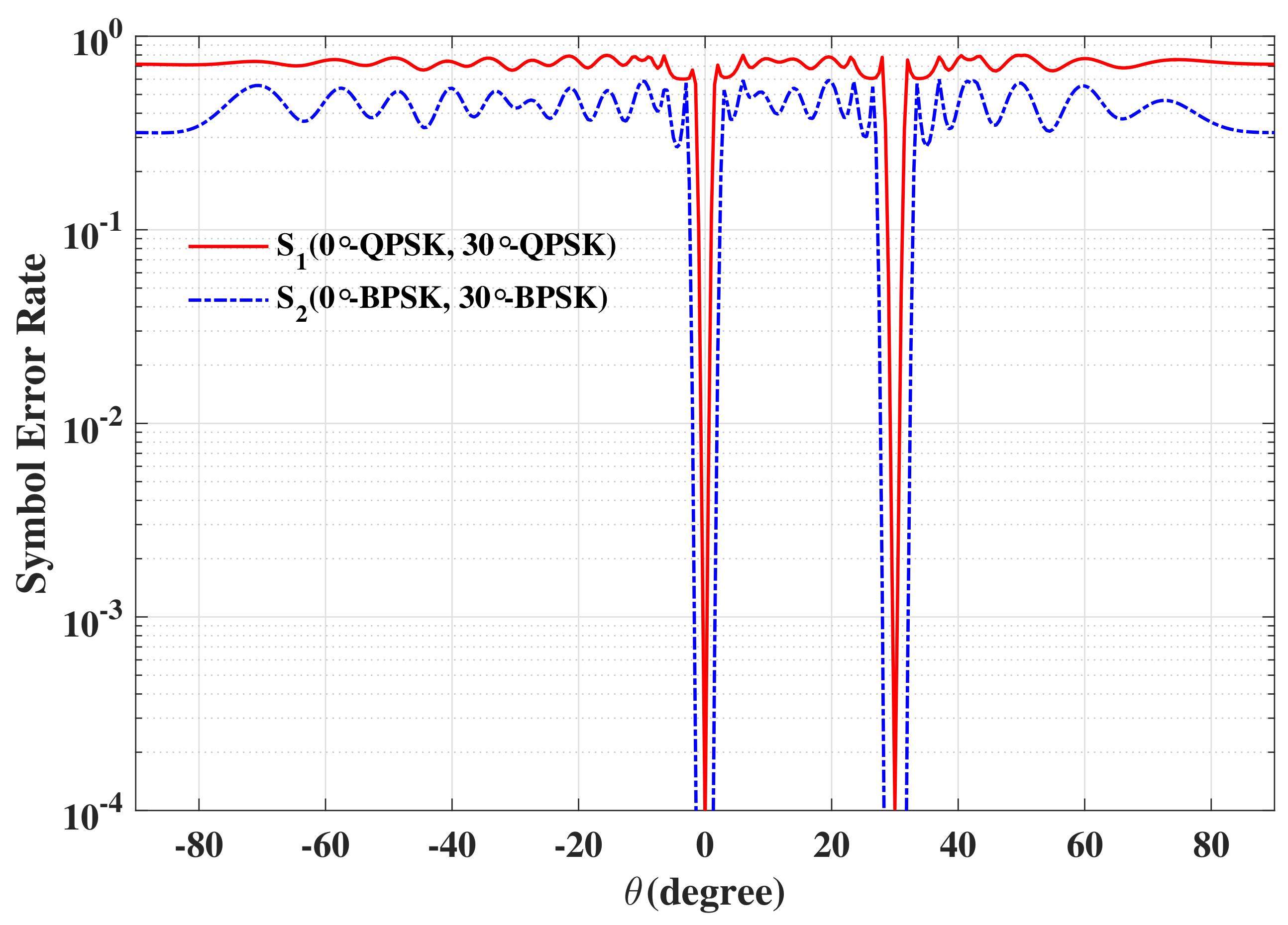
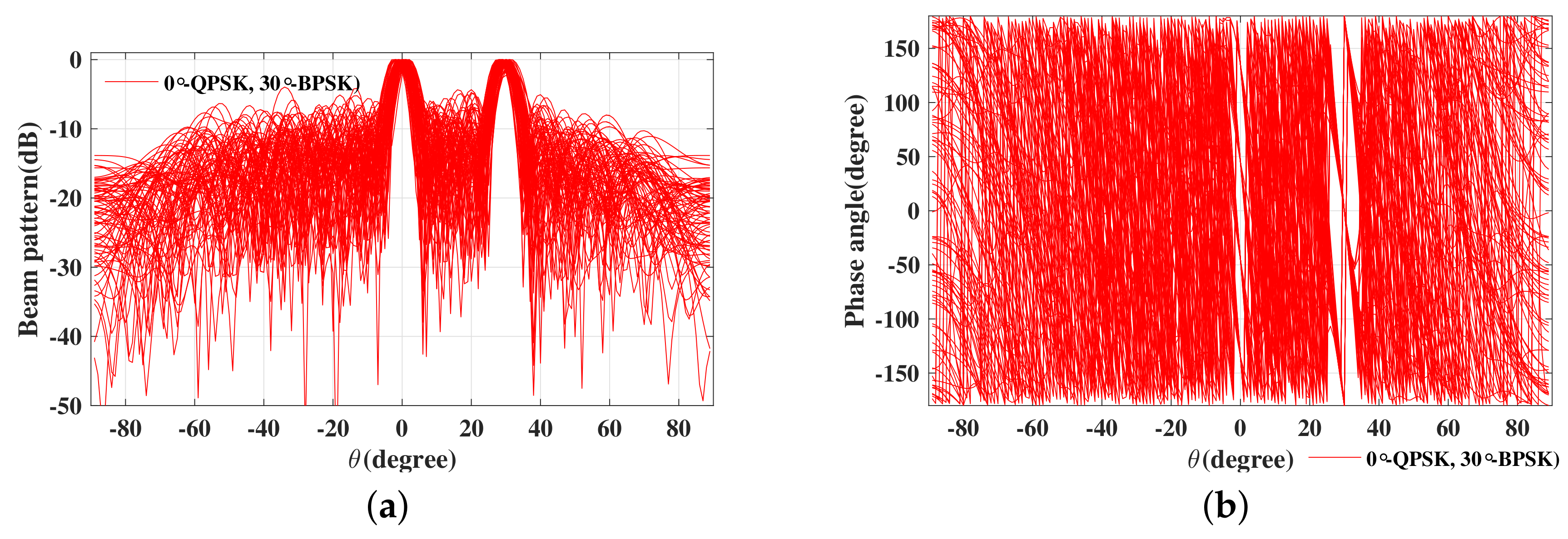
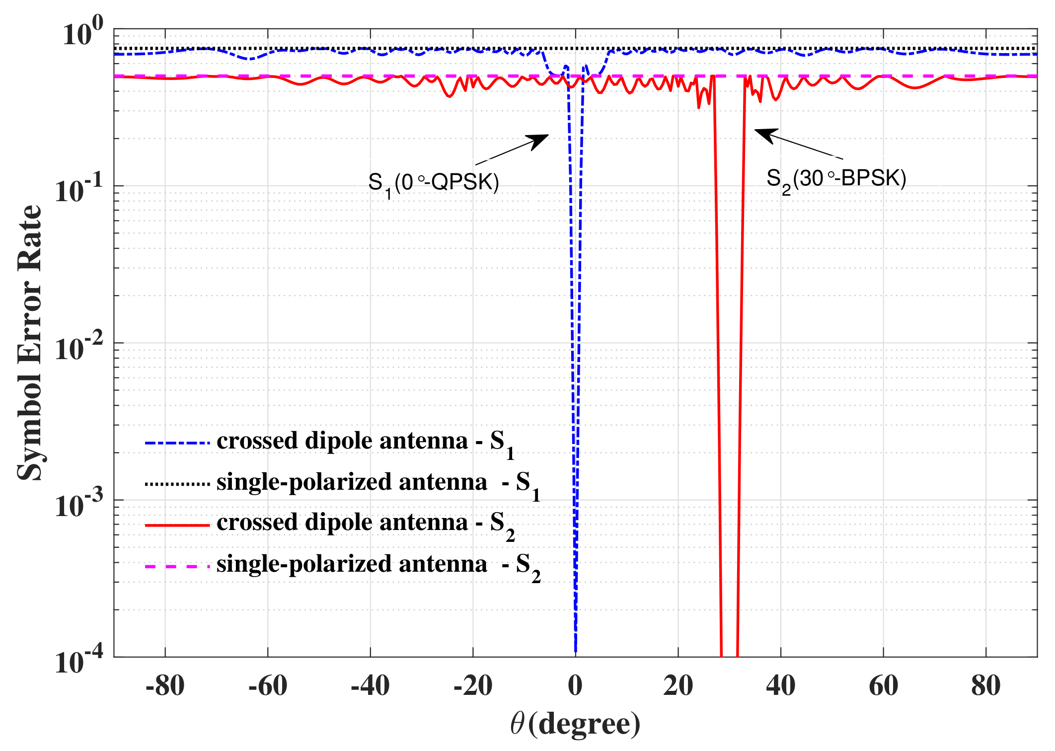
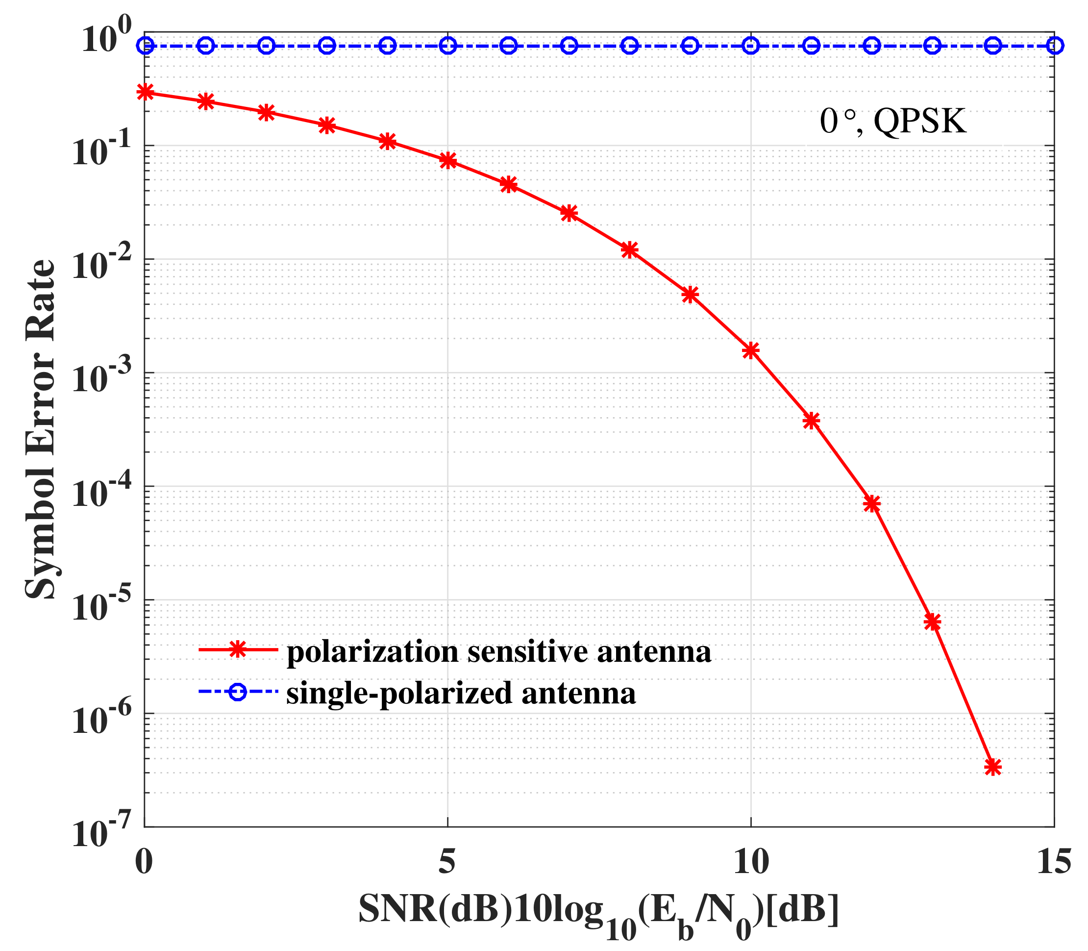
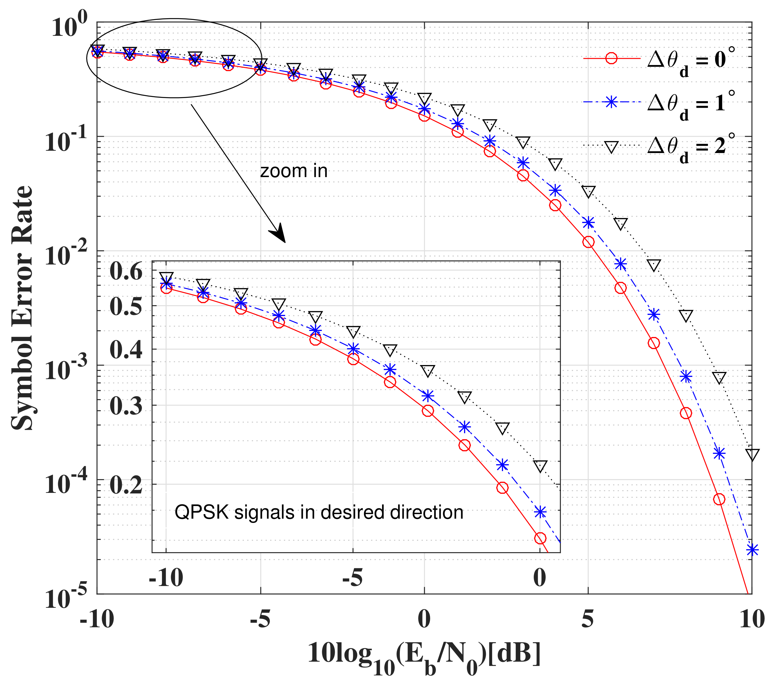
6.1. SER
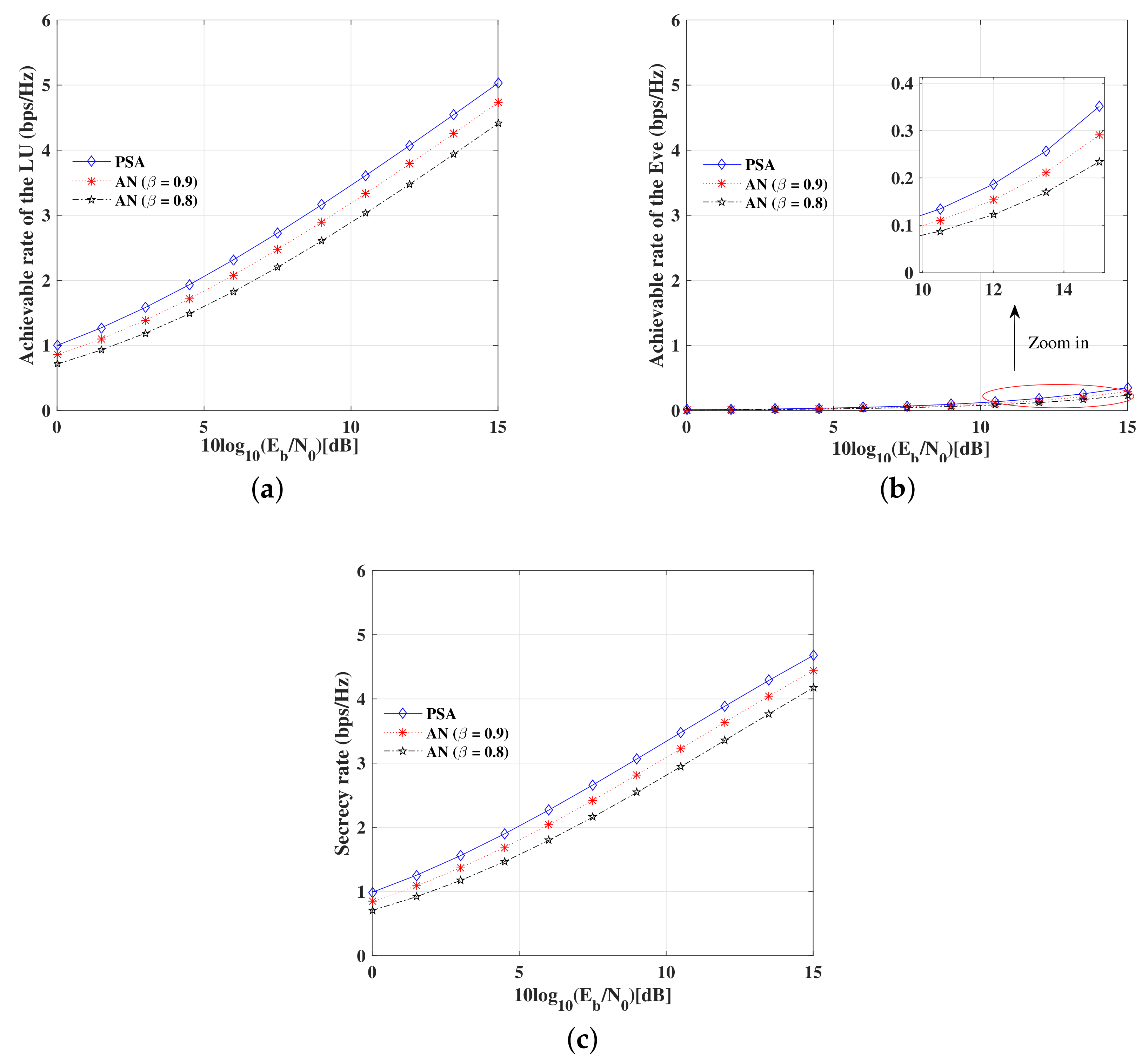
6.2. Secrecy Rate
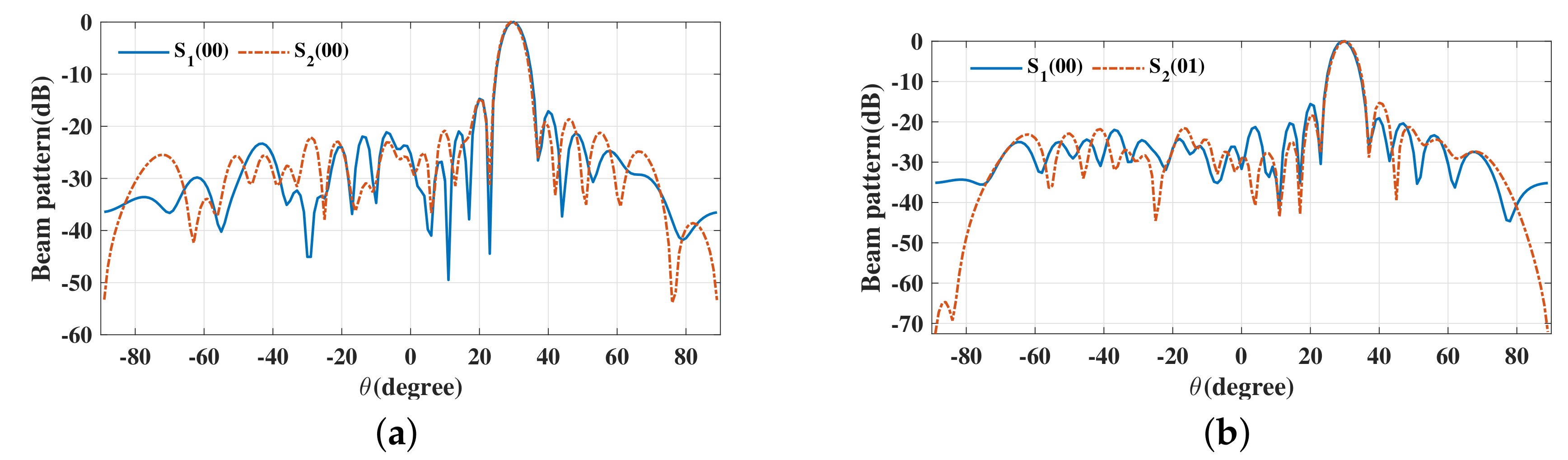
6.3. Robustness
7. Conclusions
Author Contributions
Funding
Acknowledgments
Conflicts of Interest
Appendix A
References
- Zou, Y.L.; Zhu, J.; Wang, X.B.; Hanzo, L. A survey on wireless security: Technical challenges, recent advances, and future trends. Proc. IEEE 2016, 104, 1727–1765. [Google Scholar] [CrossRef] [Green Version]
- Chen, X.M.; Ng, D.W.K.; Gerstacker, W.H.; Chen, H.H. A survey on multiple-antenna techniques for physical layer security. IEEE Commun. Surv. Tutor. 2016, 19, 1027–1053. [Google Scholar] [CrossRef]
- Mucchi, L.; Ronga, L.; Zhou, X.; Huang, K.; Chen, Y.; Wang, R. A new metric for measuring the security of an environment: The secrecy pressure. IEEE Trans. Wirel. Commun. 2017, 16, 3416–3430. [Google Scholar] [CrossRef]
- Zhang, W.; Le, M.N.; Li, B.; Wang, J.; Peng, J.Y. Directional modulation-enhanced multiple antenna arrays for secure and precise wireless transmission. Sensors 2019, 19, 4833. [Google Scholar] [CrossRef] [PubMed] [Green Version]
- Chisci, G.; Conti, A.; Mucchi, L.; Win, M.Z. Intrinsic secrecy in inhomogeneous stochastic networks. IEEE/ACM Trans. Netw. 2019, 27, 1291–1304. [Google Scholar] [CrossRef]
- Rabbachin, A.; Conti, A.; Win, M.Z. Wireless network intrinsic secrecy. IEEE/ACM Trans. Netw. 2015, 23, 56–69. [Google Scholar] [CrossRef] [Green Version]
- Wu, Y.; Khisti, A.; Xiao, C.; Caire, G.; Wong, K.K.; Gao, X.Q. A survey of physical layer security techniques for 5G wireless networks and challenges ahead. IEEE J. Sel. Areas Commun. 2018, 36, 679–695. [Google Scholar] [CrossRef] [Green Version]
- Shu, F.; Shen, T.; Xu, L.; Qin, Y.L.; Wang, S.M.; Jin, S.; You, X.H.; Wang, J.Z. Directional modulation: A physical-layer security solution to B5G and future wireless networks. IEEE Netw. 2019, 1–6. [Google Scholar] [CrossRef]
- Babakhani, A.; Rutledge, D.B.; Hajimiri, A. Transmitter architectures based on near-field direct antenna modulation. IEEE J. Solid-State Circuits 2008, 43, 2674–2692. [Google Scholar] [CrossRef] [Green Version]
- Babakhani, A.; Rutledge, D.B.; Hajimiri, A. Near-field direct antenna modulation. IEEE Microw. Mag. 2009, 10, 3646. [Google Scholar] [CrossRef]
- Daly, M.P.; Bernhard, J.T. Directional modulation technique for phased arrays. IEEE Trans. Antennas Propag. 2009, 57, 2633–2640. [Google Scholar] [CrossRef]
- Shi, H.Z.; Alan, T. Direction dependent antenna modulation using a two element array. In Proceedings of the 2011 IEEE European Conference on Antennas and Propagation (EuCAP), Rome, Italy, 11–15 May 2011; pp. 812–815. [Google Scholar]
- Daly, M.P.; Daly, E.L.; Bernhard, J.T. Demonstration of directional modulation using a phased array. IEEE Trans. Antennas Propag. 2010, 58, 1545–1550. [Google Scholar] [CrossRef]
- Daly, M.P.; Bernhard, J.T. Beamsteering in pattern reconfigurable arrays using directional modulation. IEEE Trans. Antennas Propag. 2010, 58, 2259–2265. [Google Scholar] [CrossRef]
- Shi, H.Z.; Alan, T. Characteristics of a two element direction dependent antenna array. In Proceedings of the 2011 IEEE Loughborough Antennas and Propagation Conference (LAPC), Loughborough, UK, 14–15 November 2011; pp. 1–4. [Google Scholar]
- Shi, H.Z.; Alan, T. Secure physical-layer communication based on directly modulated antenna arrays. In Proceedings of the 2012 IEEE Loughborough Antennas and Propagation Conference (LAPC), Loughborough, UK, 12–13 November 2012; pp. 1–4. [Google Scholar]
- Hong, T.; Song, M.Z.; Liu, Y. Dual-beam directional modulation technique for physical-layer secure communication. IEEE Antennas Wirel. Propag. Lett. 2011, 10, 1417–1420. [Google Scholar] [CrossRef]
- Valliappan, N.; Lozano, A.; Heath, R.W. Antenna subset modulation for secure millimeter-wave wireless communication. IEEE Trans. Commun. 2013, 61, 3231–3245. [Google Scholar] [CrossRef] [Green Version]
- Liu, F.; Wang, L.; Xie, J. Directional modulation technique for linear sparse arrays. IEEE Access 2019, 7, 13230–13240. [Google Scholar] [CrossRef]
- Hong, T.; Song, M.Z.; Liu, Y. RF directional modulation technique using a switched antenna array for physical layer secure communication applications. Prog. Electromagn. Res. 2011, 116, 363–379. [Google Scholar] [CrossRef] [Green Version]
- Zhu, Q.J.; Yang, S.W.; Yao, R.L. Directional modulation based on 4-D antenna arrays. IEEE Trans. Antennas Propag. 2013, 62, 621–628. [Google Scholar] [CrossRef]
- Ding, Y.; Fusco, V.; Anil, C. Circular directional modulation transmitter array. IET Microw. Antennas Propag. 2017, 11, 1909–1917. [Google Scholar] [CrossRef] [Green Version]
- Ding, Y.; Fusco, V. A synthesis-free directional modulation transmitter using retrodirective array. IEEE J. Sel. Top. Signal Process. 2016, 11, 428–441. [Google Scholar] [CrossRef]
- Ding, Y.; Fusco, V. Orthogonal vector approach for synthesis of multi-beam directional modulation transmitters. IEEE Antennas Wirel. Propag. Lett. 2015, 14, 1330–1333. [Google Scholar] [CrossRef] [Green Version]
- Shu, F.; Wu, X.M.; Li, J.; Chen, R.Q.; Vucetic, B. Robust synthesis scheme for secure multi-beam directional modulation in broadcasting systems. IEEE Access 2016, 4, 6614–6623. [Google Scholar] [CrossRef]
- Shu, F.; Xu, L.; Wang, J.Z.; Zhu, W.; Zhou, X.B. Artificial-noise-aided secure multicast precoding for directional modulation systems. IEEE Trans. Veh. Technol. 2018, 67, 6658–6662. [Google Scholar] [CrossRef]
- Christopher, R.M.; Borah, D.K. Iterative convex optimization of multi-beam directional modulation with artificial noise. IEEE Commun. Lett. 2018, 22, 1712–1715. [Google Scholar] [CrossRef]
- Xie, T.; Zhu, J.; Li, Y. Artificial-noise-aided zero-forcing synthesis approach for secure multi-beam directional modulation. IEEE Commun. Lett. 2018, 22, 276–279. [Google Scholar] [CrossRef]
- Hafez, M.; Arslan, H. On directional modulation: An analysis of transmission scheme with multiple directions. In Proceedings of the 2015 IEEE International Conference on Communications Workshops, (ICCW), London, UK, 8–12 June 2015; pp. 459–463. [Google Scholar]
- Hafez, M.; Khattab, T.; Elfouly, T. Secure multiple-users transmission using multi-path directional modulation. In Proceedings of the 2016 IEEE International Conference on Communications (ICC), Kuala Lumpur, Malaysia, 22–27 May 2016; pp. 1–5. [Google Scholar]
- Akl, A.; Elnakib, A.; Kishk, S. Broadcasting multi-beams antenna subset modulation for secure millimeter-wave wireless communications. Wirel. Pers. Commun. 2017, 12, 1–15. [Google Scholar] [CrossRef]
- Wei, D.; Feng, C.; Guo, C. An optimal pre-compensation based joint polarization-amplitude-phase modulation scheme for the power amplifier energy efficiency improvement. In Proceedings of the 2013 IEEE International Conference on Communications (ICC), Budapest, Hungary, 9–13 June 2013; pp. 4137–4142. [Google Scholar]
- Wei, D.; Zhang, M.; Fan, W. A spectrum efficient polarized PSK/QAM scheme in the wireless channel with polarization dependent loss effect. In Proceedings of the 2015 IEEE International Conference on Telecommunications (ICT), Sydney, NSW, Australia, 27–29 June 2015; pp. 249–255. [Google Scholar]
- Luo, Z.K.; Wang, H.L. Dual-polarized phased array based polarization state modulation for physical-layer secure communication. IEICE Trans. Fundam. Electron. Commun. Comput. Sci. 2018, E101-A, 740–747. [Google Scholar] [CrossRef]
- Luo, Z.K.; Wang, H.L.; Lv, W.H. Directional polarization modulation for secure transmission in dual-polarized satellite MIMO systems. In Proceedings of the 2016 IEEE International Conference on Wireless Communications and Signal Processing (WCSP), Yangzhou, China, 13–15 October 2016; pp. 1–5. [Google Scholar]
- Zhang, B.; Liu, W.; Lan, X. Directional modulation design based on crossed-dipole arrays for two signals with orthogonal polarisations. In Proceedings of the 2018 IEEE European Conference on Antennas and Propagation (EuCAP), London, UK, 9–13 April 2018; pp. 1–5. [Google Scholar]
- Wang, W.Q.; Zheng, Z. Hybrid MIMO and phased-array directional modulation for physical layer security in mmWave wireless communications. IEEE J. Sel. Areas Commun. 2018, 36, 1383–1396. [Google Scholar] [CrossRef]
- Compton, R. The tripole antenna: An adaptive array with full polarization flexibility. IEEE Trans. Antennas Propag. 1981, 29, 944–952. [Google Scholar] [CrossRef]
- Zhou, C.; Gu, Y.; He, S.B.; Shi, Z. A robust and efficient algorithm for coprime array adaptive beamforming. IEEE Trans. Veh. Technol. 2018, 67, 1099–1112. [Google Scholar] [CrossRef]
- Cheng, Q.; Fusco, V.; Zhu, J.; Wang, S.; Wang, F.F. WFRFT-aided power-efficient multi-beam directional modulation schemes based on frequency diverse array. IEEE Trans. Wirel. Commun. 2019, 18, 5211–5226. [Google Scholar] [CrossRef] [Green Version]
- Ding, Y. Establishing metrics for assessing the performance of directional modulation systems. IEEE Trans. Antennas Propag. 2014, 2, 2745–2755. [Google Scholar] [CrossRef] [Green Version]
- Ding, Y.; Fusco, V. A review of directional modulation technology. Int. J. Microw. Wirel. Technol. 2016, 8, 981–993. [Google Scholar] [CrossRef] [Green Version]
- Zhou, C.; Gu, Y.; Fan, X.; Shi, Z.; Mao, G.; Zhang, Y.D. Direction-of-arrival estimation for coprime array via virtual array interpolation. IEEE Trans. Signal Process. 2018, 66, 5956–5971. [Google Scholar] [CrossRef]
- Zhou, C.; Gu, Y.; Shi, Z.; Zhang, Y.D. Off-grid direction-of-arrival estimation using coprime array interpolation. IEEE Signal Process. Lett. 2018, 25, 1710–1714. [Google Scholar] [CrossRef]
- Zhou, C.; Gu, Y.; Zhang, Y.D.; Shi, Z.; Jin, T.; Wu, X.D. Compressive sensing based coprime array direction-of-arrival estimation. IET Commun. 2017, 11, 1719–1724. [Google Scholar] [CrossRef]
- Shu, F.; Zhu, W.; Zhou, X.; Li, J.; Lu, J. Robust secure transmission of using main-lobe-integration-based leakage beamforming in directional modulation MU-MIMO systems. IEEE Syst. J. 2018, 12, 3775–3785. [Google Scholar] [CrossRef] [Green Version]
- Pratt, T.; Walkenhorst, B.; Nguyen, S. Adaptive polarization transmission of OFDM signals in channels with polarization mode dispersion and polarization-dependent loss. IEEE Trans. Wirel. Commun. 2009, 8, 3354–3359. [Google Scholar] [CrossRef]
- Chen, H.; Shao, H.; Chen, H. Angle-range-polarization-dependent beamforming for polarization sensitive frequency diverse array. EURASIP J. Adv. Signal Process. 2019, 2019, 23. [Google Scholar] [CrossRef] [Green Version]


| Symbols | Usage | Symbols | Usage |
|---|---|---|---|
| Transpose operator | Complex conjugate transpose operator | ||
| Inverse operator | Moore-Penrose pseudo inverse operator | ||
| Modulus operator | -norm operator | ||
| ⊗ | Kronecker product operator | Quadrature operator | |
| Sum operator | Complementary error function | ||
| Phase acquisition function | Standard normal distribution | ||
| Returns the largest element | |||
| Real number, complex number | Identity matrix with size |
© 2019 by the authors. Licensee MDPI, Basel, Switzerland. This article is an open access article distributed under the terms and conditions of the Creative Commons Attribution (CC BY) license (http://creativecommons.org/licenses/by/4.0/).
Share and Cite
Zhang, W.; Li, B.; Le, M.; Wang, J.; Peng, J. Directional Modulation Technique Using a Polarization Sensitive Array for Physical Layer Security Enhancement. Sensors 2019, 19, 5396. https://doi.org/10.3390/s19245396
Zhang W, Li B, Le M, Wang J, Peng J. Directional Modulation Technique Using a Polarization Sensitive Array for Physical Layer Security Enhancement. Sensors. 2019; 19(24):5396. https://doi.org/10.3390/s19245396
Chicago/Turabian StyleZhang, Wei, Bin Li, Mingnan Le, Jun Wang, and Jinye Peng. 2019. "Directional Modulation Technique Using a Polarization Sensitive Array for Physical Layer Security Enhancement" Sensors 19, no. 24: 5396. https://doi.org/10.3390/s19245396