Compact Inner-Wall Grating Slot Microring Resonator for Label-Free Sensing

 ,
,
Abstract
:1. Introduction
2. Structure Design and Operation Principle
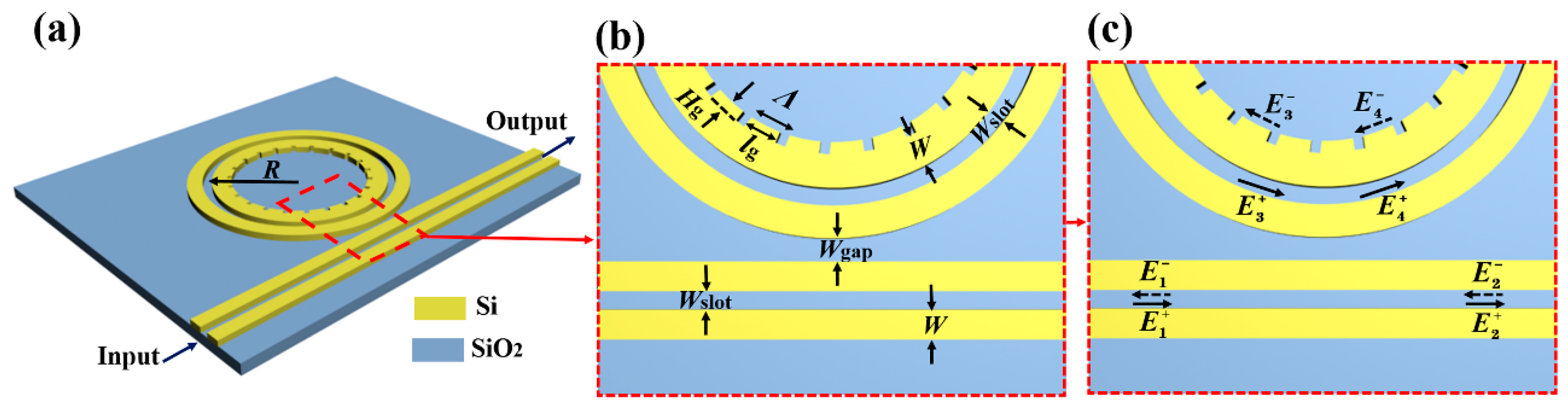
2.1. Structure Design
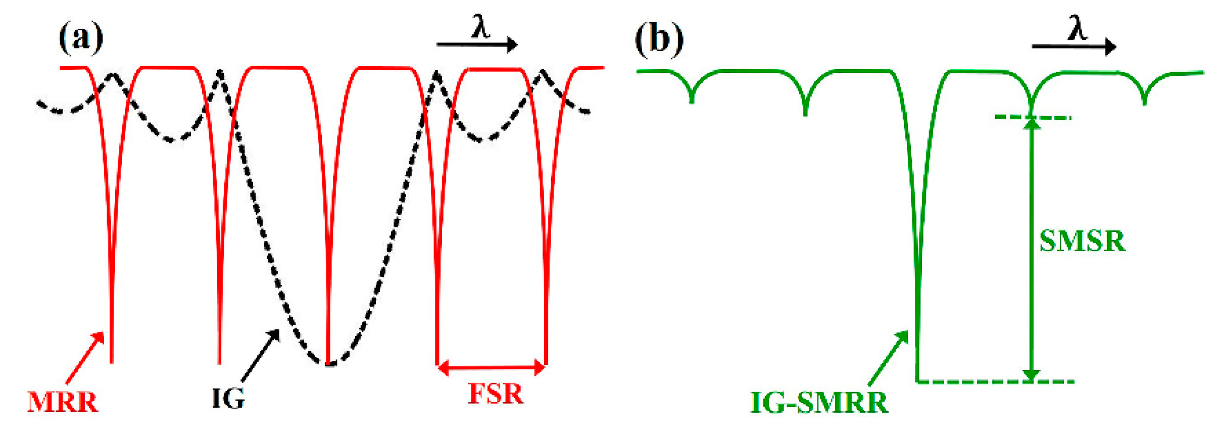
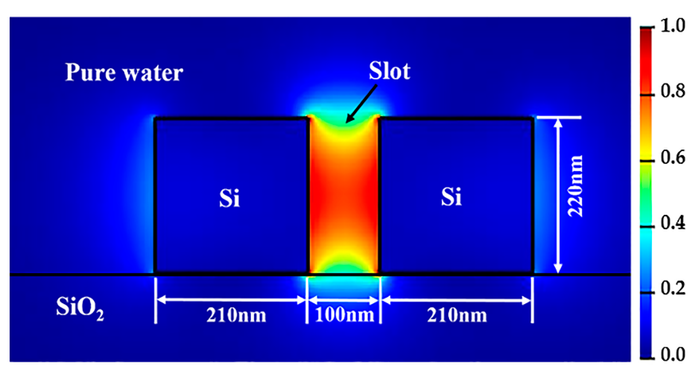
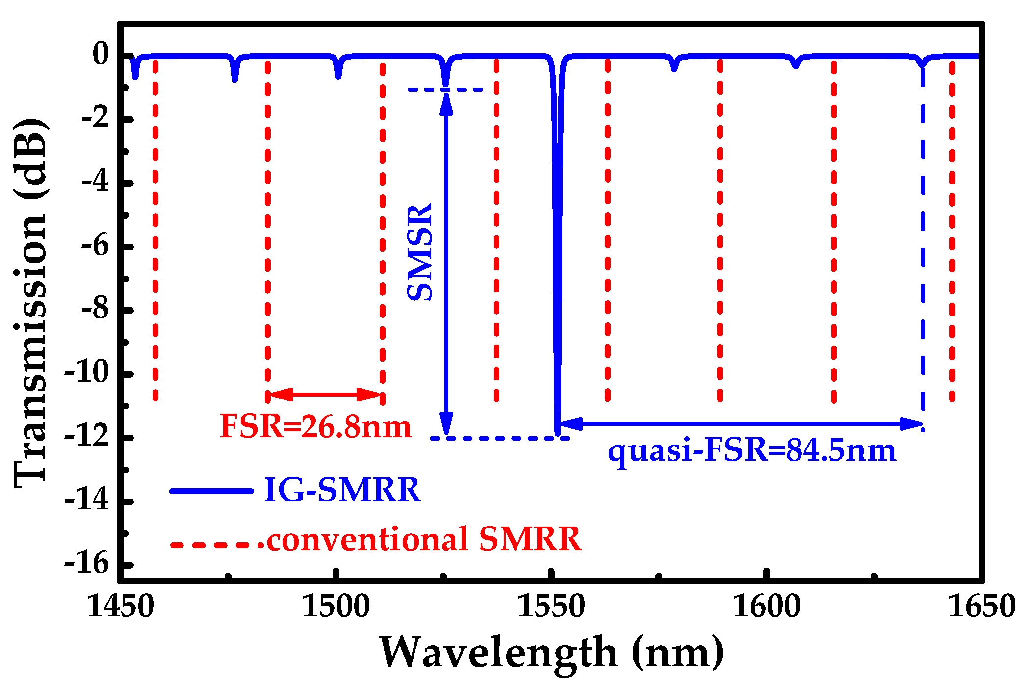
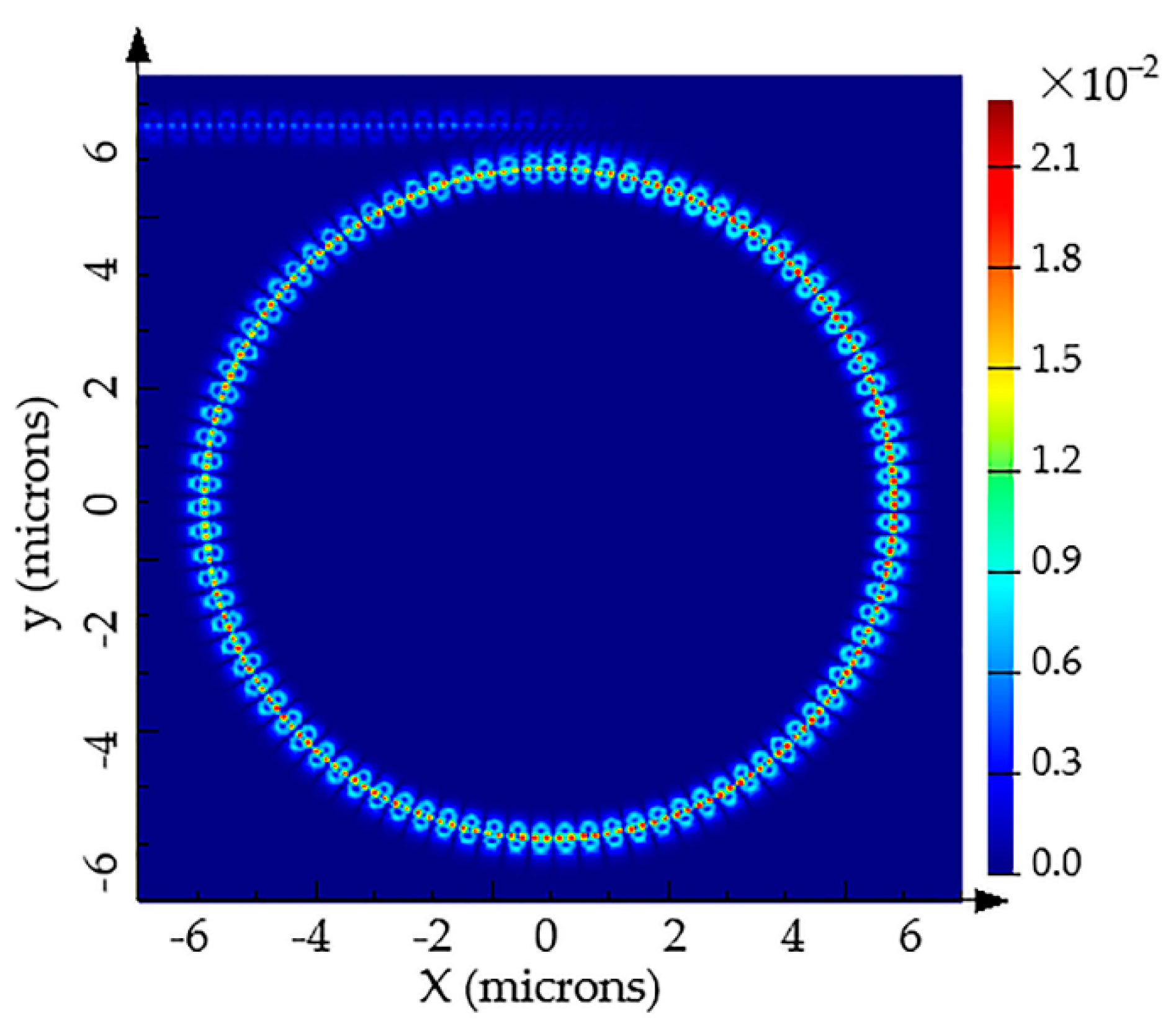
2.2. Operation Principle
3. Results and Discussion
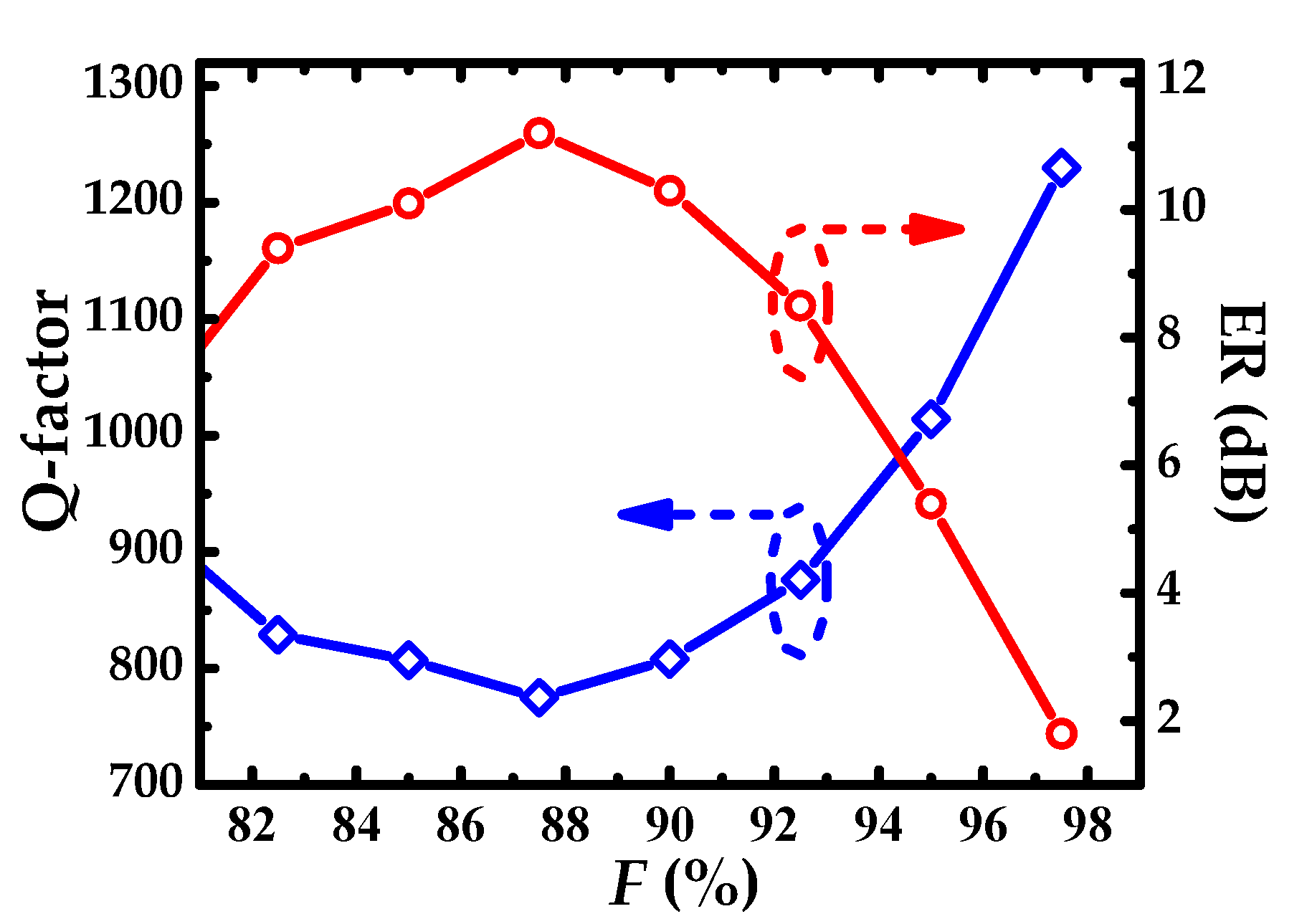
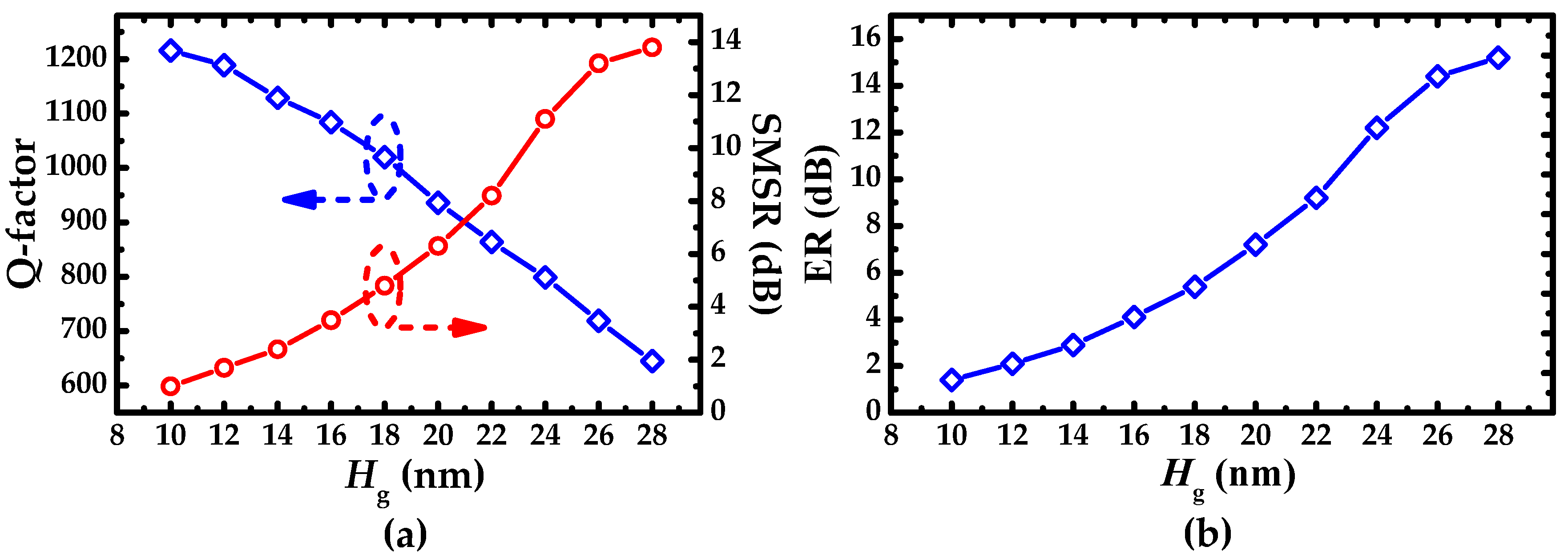
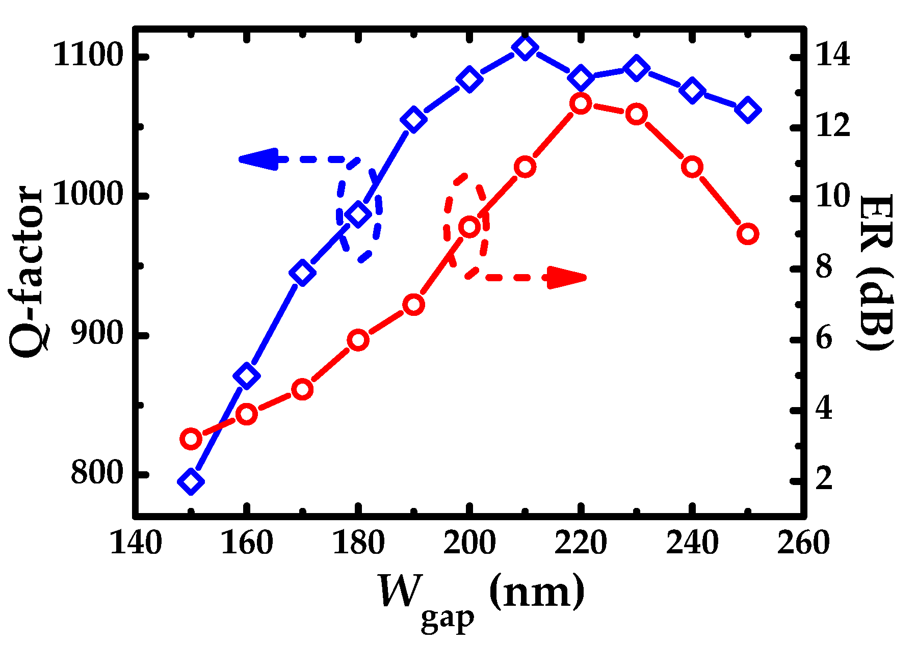
3.1. Optimization of Parameters
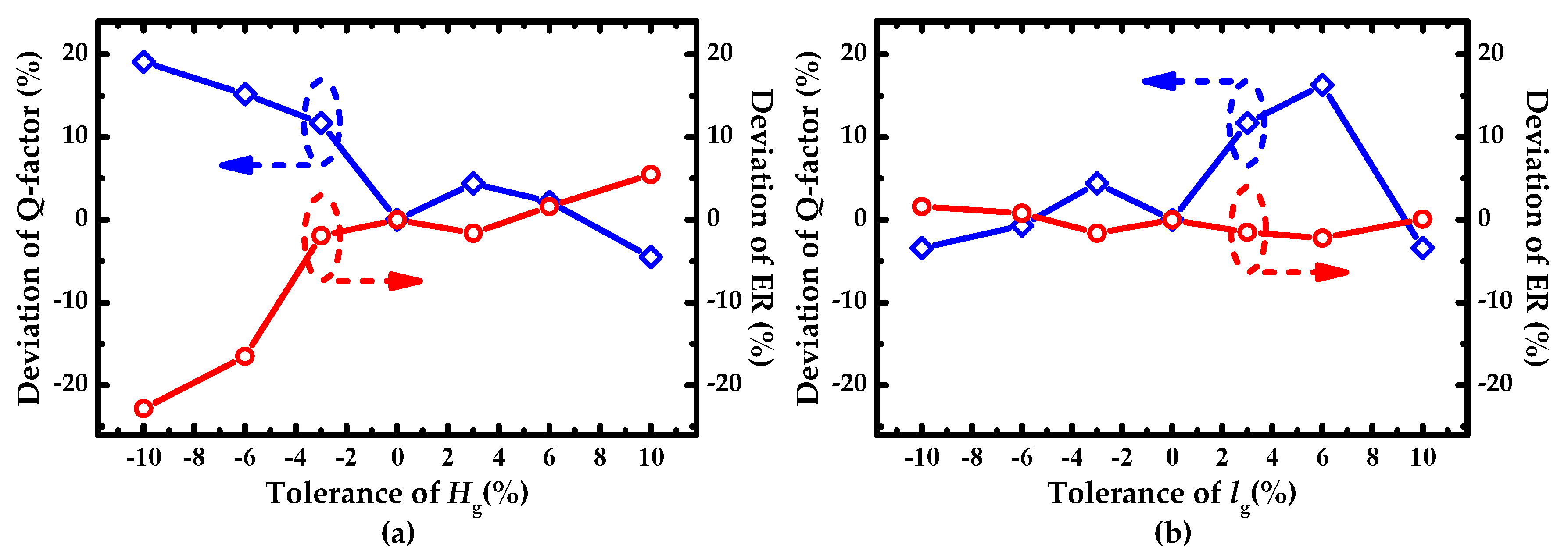
3.2. Deviation Analysis of the Hg and lg in the Fabrication Process
3.3. Bulk Sensing Analysis
4. Conclusions
Author Contributions
Funding
Acknowledgments
Conflicts of Interest
References
- Fan, X.D.; White, I.M.; Shopova, S.I.; Zhu, H.Y.; Suter, J.D.; Sun, Y.Z. Sensitive optical biosensors for unlabeled targets: A review. Anal. Chim. Acta 2008, 620, 8–26. [Google Scholar] [CrossRef] [PubMed]
- Sun, L.; Yuan, J.H.; Ma, T.; Sang, X.Z.; Yan, B.B.; Wang, K.R.; Yu, C.X. Design and optimization of silicon concentric dual-microring resonators for refractive index sensing. Opt. Commun. 2017, 395, 212–216. [Google Scholar] [CrossRef]
- Xu, Q.F.; Fattal, D.; Beausoleil, R.G. Silicon microring resonators with 1.5-mu m radius. Opt. Express 2008, 16, 4309–4315. [Google Scholar] [CrossRef] [PubMed]
- Dai, D.X.; He, S.L. Highly sensitive sensor based on an ultra-high-Q Mach-Zehnder interferometer-coup led microring. J. Opt. Soc. Am. B 2009, 26, 511–516. [Google Scholar] [CrossRef]
- Yuan, G.; Gao, L.; Chen, Y.; Wang, J.; Ren, P.; Wang, Z. Efficient optical biochemical sensor with slotted Bragg-grating-based Fabry–Perot resonator structure in silicon-on-insulator platform. Opt. Quantum Electron. 2014, 47, 247–255. [Google Scholar] [CrossRef]
- Nemova, G.; Kashyap, R. Theoretical model of a planar integrated refractive index sensor based on surface plasmon-polariton excitation with a long period grating. J. Opt. Soc. Am. B 2007, 24, 2696–2701. [Google Scholar] [CrossRef]
- Chang, Y.; Jiang, Y.Y. Highly Sensitive Plasmonic Sensor Based on Fano Resonance from Silver Nanoparticle Heterodimer Array on a Thin Silver Film. Plasmonics 2014, 9, 499–505. [Google Scholar] [CrossRef]
- Zamora, V.; Lützow, P.; Weiland, M.; Pergande, D. A Highly Sensitive Refractometric Sensor Based on Cascaded SiN Microring Resonators. Sensors 2013, 13, 14601–14610. [Google Scholar] [CrossRef]
- Wei, H.; Krishnaswamy, S. Polymer micro-ring resonator integrated with a fiber ring laser for ultrasound detection. Opt. Lett. 2017, 42, 2655. [Google Scholar] [CrossRef]
- Grist, S.M.; Schmidt, S.A.; Flueckiger, J.; Donzella, V.; Shi, W.; Fard, S.T.; Kirk, J.T.; Ratner, D.M.; Cheung, K.C.; Chrostowski, L. Silicon photonic micro-disk resonators for label-free biosensing. Opt. Express 2013, 21, 7994–8006. [Google Scholar] [CrossRef]
- Amiri, I.S.; Ariannejad, M.M.; Daud, S.; Yupapin, P. High sensitivity temperature sensor silicon-based microring resonator using the broadband input spectrum. Results Phys. 2018, 9, 1578–1584. [Google Scholar] [CrossRef]
- Ruan, Z.; Shen, L.; Zheng, S.; Wang, J. Subwavelength grating slot (SWGS) waveguide on silicon platform. Opt. Express 2017, 25, 18250. [Google Scholar] [CrossRef] [PubMed]
- Chao, C.Y.; Guo, L.J. Design and optimization of microring resonators in biochemical sensing applications. J. Lightwave Technol. 2006, 24, 1395–1402. [Google Scholar] [CrossRef]
- De Vos, K.; Bartolozzi, I.; Schacht, E.; Bienstman, P.; Baets, R. Silicon-on-Insulator microring resonator for sensitive and label-free biosensing. Opt. Express 2007, 15, 7610–7615. [Google Scholar] [CrossRef]
- Kolli, V.R.; Srinivasulu, T.; Hegde, G.; Badrinarayana, T.; Talabattula, S. Design and analysis of serially coupled double microring resonator based force sensor for 1 mu N range measurement. Optik 2017, 131, 1063–1070. [Google Scholar] [CrossRef]
- Eid, N.; Boeck, R.; Jayatilleka, H.; Chrostowski, L.; Shi, W.; Jaeger, N.A.F. FSR-free silicon-on-insulator microring resonator based filter with bent contra-directional couplers. Opt. Express 2016, 24, 29010–29022. [Google Scholar] [CrossRef]
- Xiong, Y.L.; Ye, W.N.N. Silicon Mach-Zehnder interferometer racetrack microring for sensing. In Proceedings of the Silicon Photonics IX, San Francisco, CA, USA, 1–6 February 2014; p. 89901H. [Google Scholar]
- Shi, W.; Wang, X.; Zhang, W.; Yun, H.; Lin, C.; Chrostowski, L.; Jaeger, N.A.F. Grating-coupled silicon microring resonators. Appl. Phys. Lett. 2012, 100. [Google Scholar] [CrossRef]
- Ma, T.; Sun, L.; Yuan, J.H.; Sang, X.Z.; Yan, B.B.; Wang, K.R.; Yu, C.X. Integrated label-free optical biochemical sensor with a large measurement range based on an angular grating-microring resonator. Appl. Opt. 2016, 55, 4784–4790. [Google Scholar] [CrossRef]
- Yuan, G.H.; Gao, L.; Chen, Y.R.; Liu, X.L.; Wang, J.; Wang, Z.R. Improvement of optical sensing performances of a double-slot-waveguide-based ring resonator sensor on silicon-on-insulator platform. Optik 2014, 125, 850–854. [Google Scholar] [CrossRef]
- Kang, Y.M.; Arbabi, A.; Goddard, L.L. A microring resonator with an integrated Bragg grating: A compact replacement for a sampled grating distributed Bragg reflector. Opt. Quant. Electron. 2009, 41, 689–697. [Google Scholar] [CrossRef]
- Achieve More with Light. Available online: http://www.lumerical.com (accessed on 14 November 2019).
- Bogaerts, W.; De Heyn, P.; Van Vaerenbergh, T.; De Vos, K.; Selvaraja, S.K.; Claes, T.; Dumon, P.; Bienstman, P.; Van Thourhout, D.; Baets, R. Silicon microring resonators. Laser Photonics Rev. 2012, 6, 47–73. [Google Scholar] [CrossRef]
- Cai, X.L.; Wang, J.W.; Strain, M.J.; Johnson-Morris, B.; Zhu, J.B.; Sorel, M.; O’Brien, J.L.; Thompson, M.G.; Yu, S.T. Integrated Compact Optical Vortex Beam Emitters. Science 2012, 338, 363–366. [Google Scholar] [CrossRef] [PubMed]
- Tseng, C.W.; Tsai, C.W.; Lin, K.C.; Lee, M.C.; Chen, Y.J. Study of coupling loss on strongly-coupled, ultra compact microring resonators. Opt. Express 2013, 21, 7250–7257. [Google Scholar] [CrossRef] [PubMed]
- Sang, X.; Yu, C.; Mayteevarunyoo, T.; Wang, K.; Zhang, Q.; Chu, P.L. Temperature-insensitive chemical sensor based on a fiber Bragg grating. Sens. Actuat. B Chem. 2007, 120, 754–757. [Google Scholar] [CrossRef]
- Lide, D.R. Thermochemistry, Electrochemistry, and Solution Chemistry. In Handbook of Chemistry and Physics, 95th ed.; Haynes, W.M., Bruno, T.J., Eds.; CRC: Boca Raton, FL, USA, 2015; pp. 130–142. [Google Scholar]
- Girault, P.; Lorrain, N.; Poffo, L.; Guendouz, M.; Lemaitre, J.; Lemaitre, J. Integrated polymer micro-ring resonators for optical sensing applications. J. Appl. Phys. 2015, 117, 104504. [Google Scholar] [CrossRef]
- Liu, Z.B.; Tan, Z.W.; Yin, B.; Bai, Y.L.; Jian, S.S. Refractive index sensing characterization of a singlemode-claddingless-singlemode fiber structure based fiber ring cavity laser. Opt. Express 2014, 22, 5037–5042. [Google Scholar] [CrossRef]
- Xue, L.L.; Yang, L. Sensitivity Enhancement of RI Sensor Based on SMS Fiber Structure with High Refractive Index Overlay. J. Lightwave Technol. 2012, 30, 1463–1469. [Google Scholar]
- Wu, Q.; Semenova, Y.; Wang, P.F.; Farrell, G. High sensitivity SMS fiber structure based refractometer—Analysis and experiment. Opt. Express 2011, 19, 7937–7944. [Google Scholar] [CrossRef]


| Sample | Concentration (%) | RI |
|---|---|---|
| Pure water | 1.333 | |
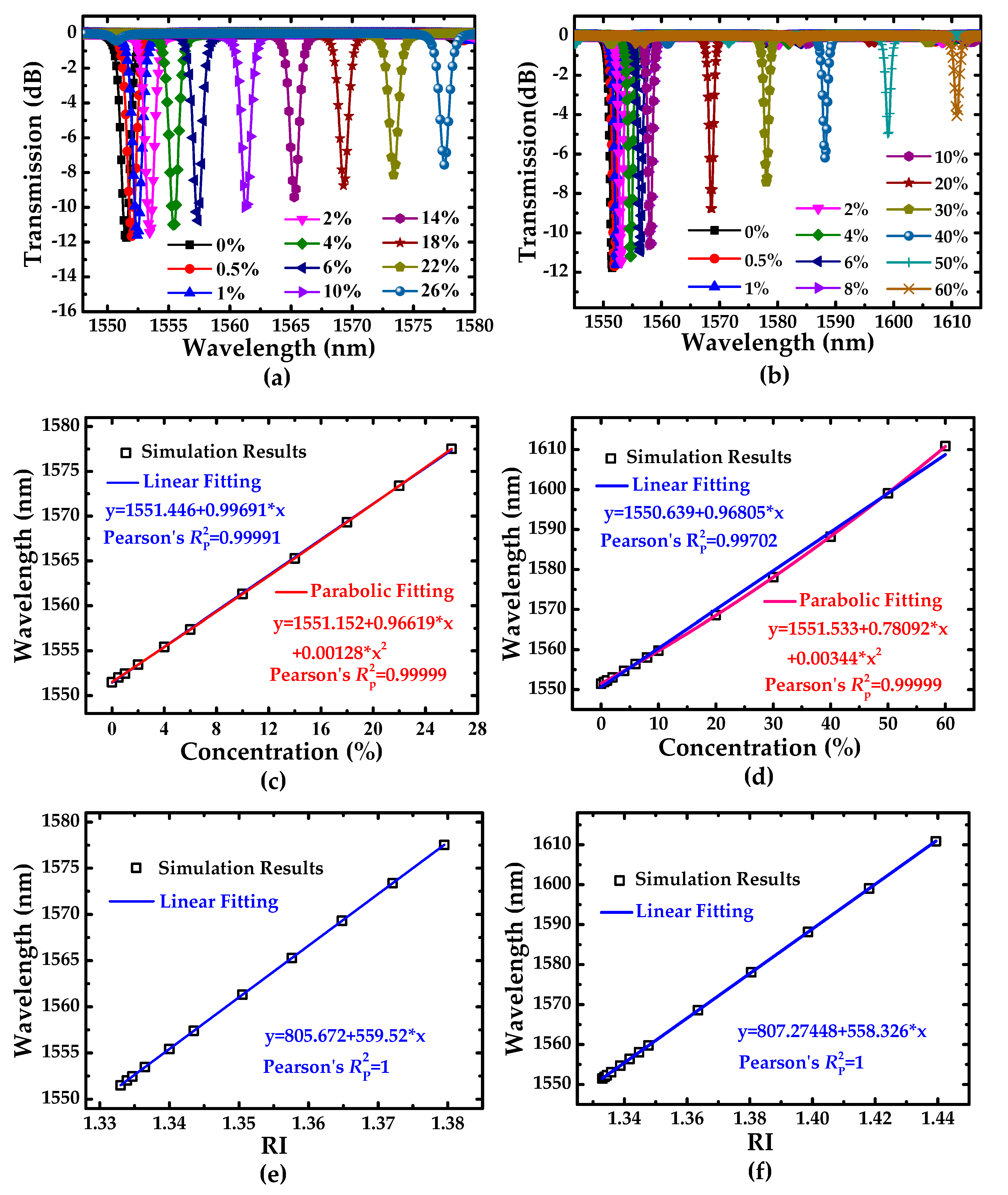
| Sodium chloride | 0.5–26 | 1.3339–1.3795 |
| D-glucose | 0.5–60 | 1.3337–1.4394 |
| Sample | Sc (pm/%) | for Linear Fit | for Parabolic Fit |
|---|---|---|---|
| Sodium Chloride | 996.91 | 0.99991 | 0.99999 |
| D-glucose | 968.05 | 0.99702 | 0.99999 |
© 2019 by the authors. Licensee MDPI, Basel, Switzerland. This article is an open access article distributed under the terms and conditions of the Creative Commons Attribution (CC BY) license (http://creativecommons.org/licenses/by/4.0/).
Share and Cite
Gu, H.; Gong, H.; Wang, C.; Sun, X.; Wang, X.; Yi, Y.; Chen, C.; Wang, F.; Zhang, D. Compact Inner-Wall Grating Slot Microring Resonator for Label-Free Sensing. Sensors 2019, 19, 5038. https://doi.org/10.3390/s19225038
Gu H, Gong H, Wang C, Sun X, Wang X, Yi Y, Chen C, Wang F, Zhang D. Compact Inner-Wall Grating Slot Microring Resonator for Label-Free Sensing. Sensors. 2019; 19(22):5038. https://doi.org/10.3390/s19225038
Chicago/Turabian StyleGu, Hongjun, He Gong, Chunxue Wang, Xiaoqiang Sun, Xibin Wang, Yunji Yi, Changming Chen, Fei Wang, and Daming Zhang. 2019. "Compact Inner-Wall Grating Slot Microring Resonator for Label-Free Sensing" Sensors 19, no. 22: 5038. https://doi.org/10.3390/s19225038