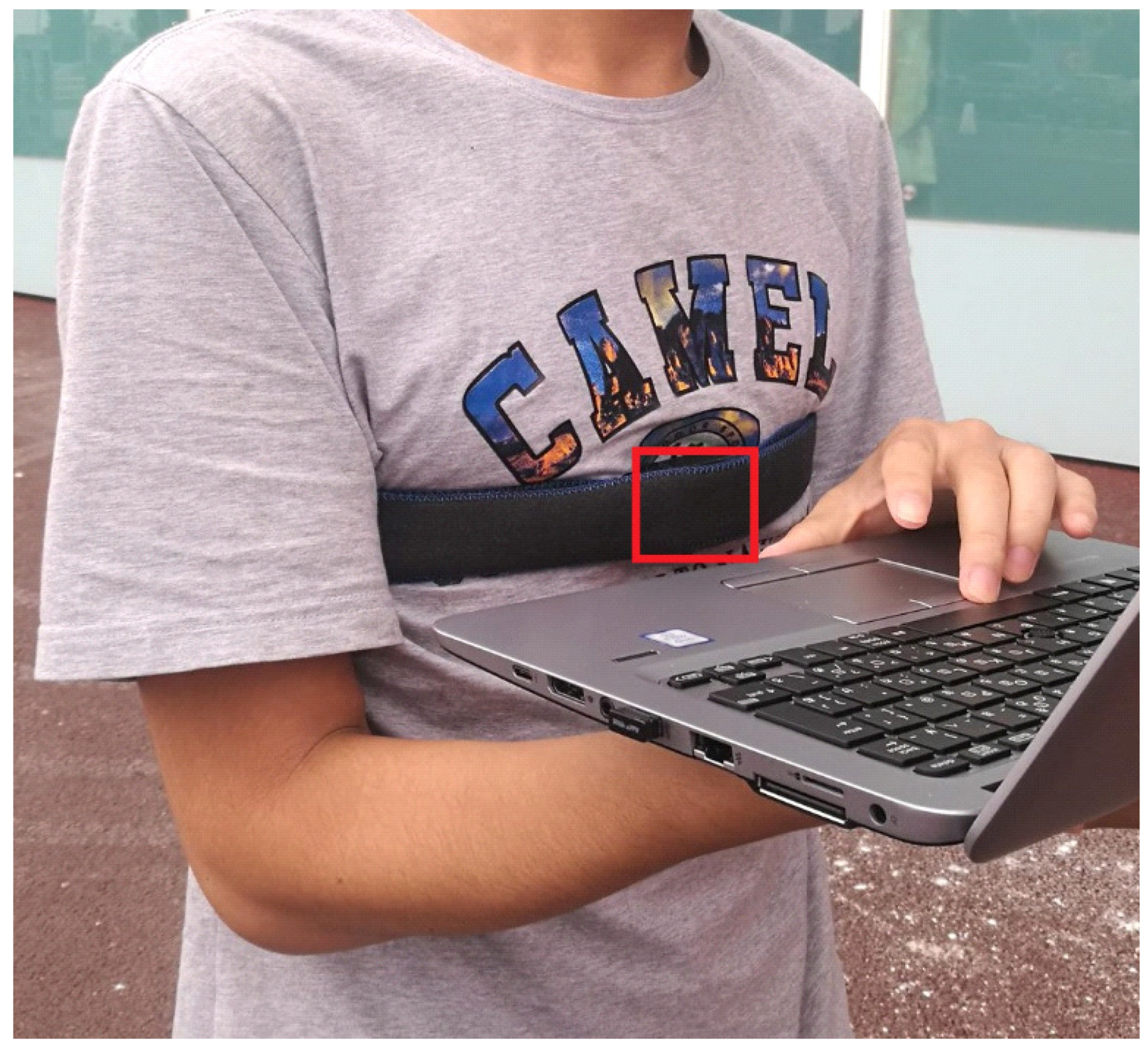
Indoor Positioning System Based on Chest-Mounted IMU

 , , ,
, , ,
Abstract
:1. Introduction
- A novel chest-mounted IMU-based PDR for body-suit-type systems is proposed.
- Step-length estimation for a chest-mounted IMU is proposed.
- A complete system for multifloor navigation tasks was implemented and the code is open (https://github.com/rairyuu/PDR-with-Map-Matching).
2. Related Work
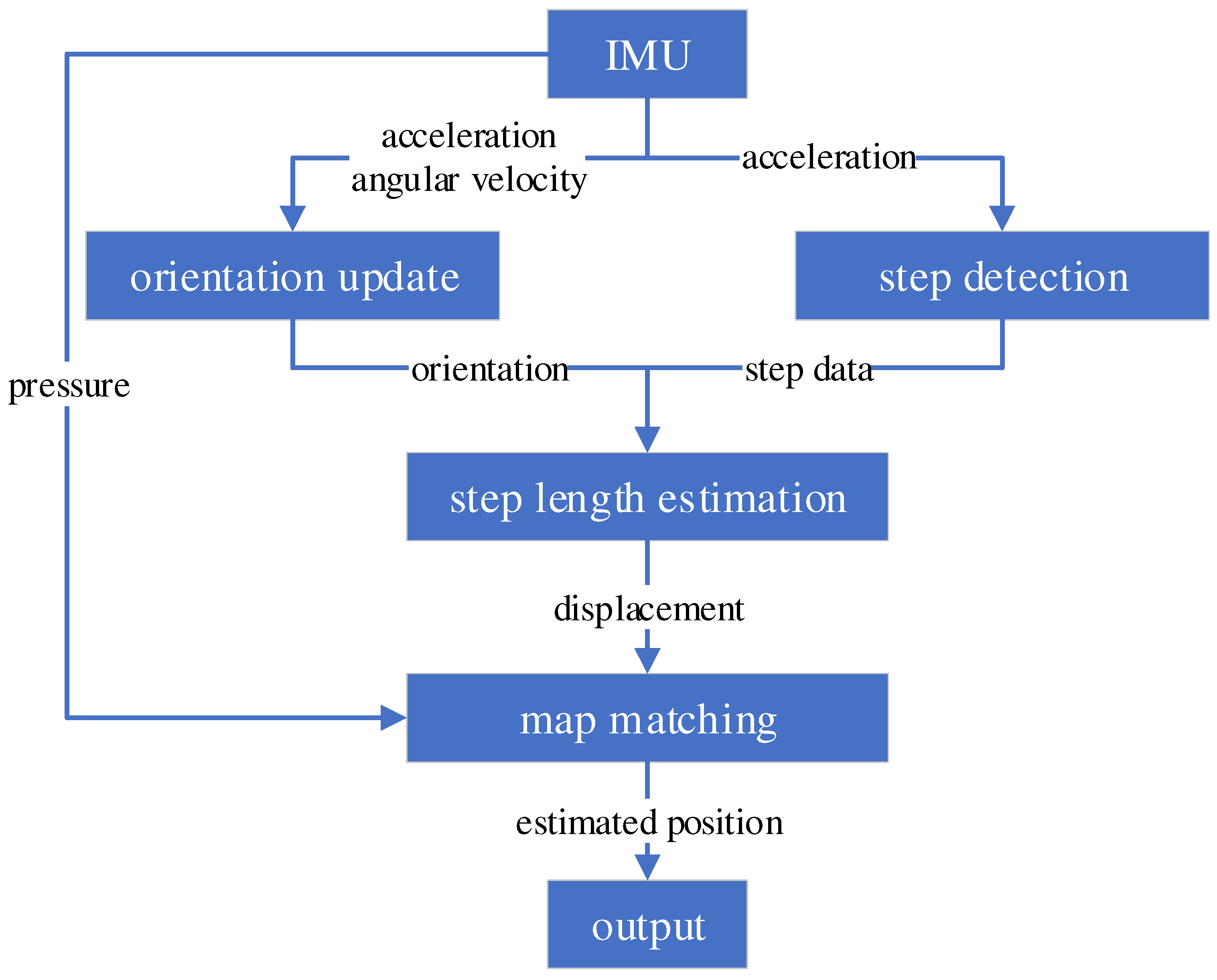
3. Proposed System
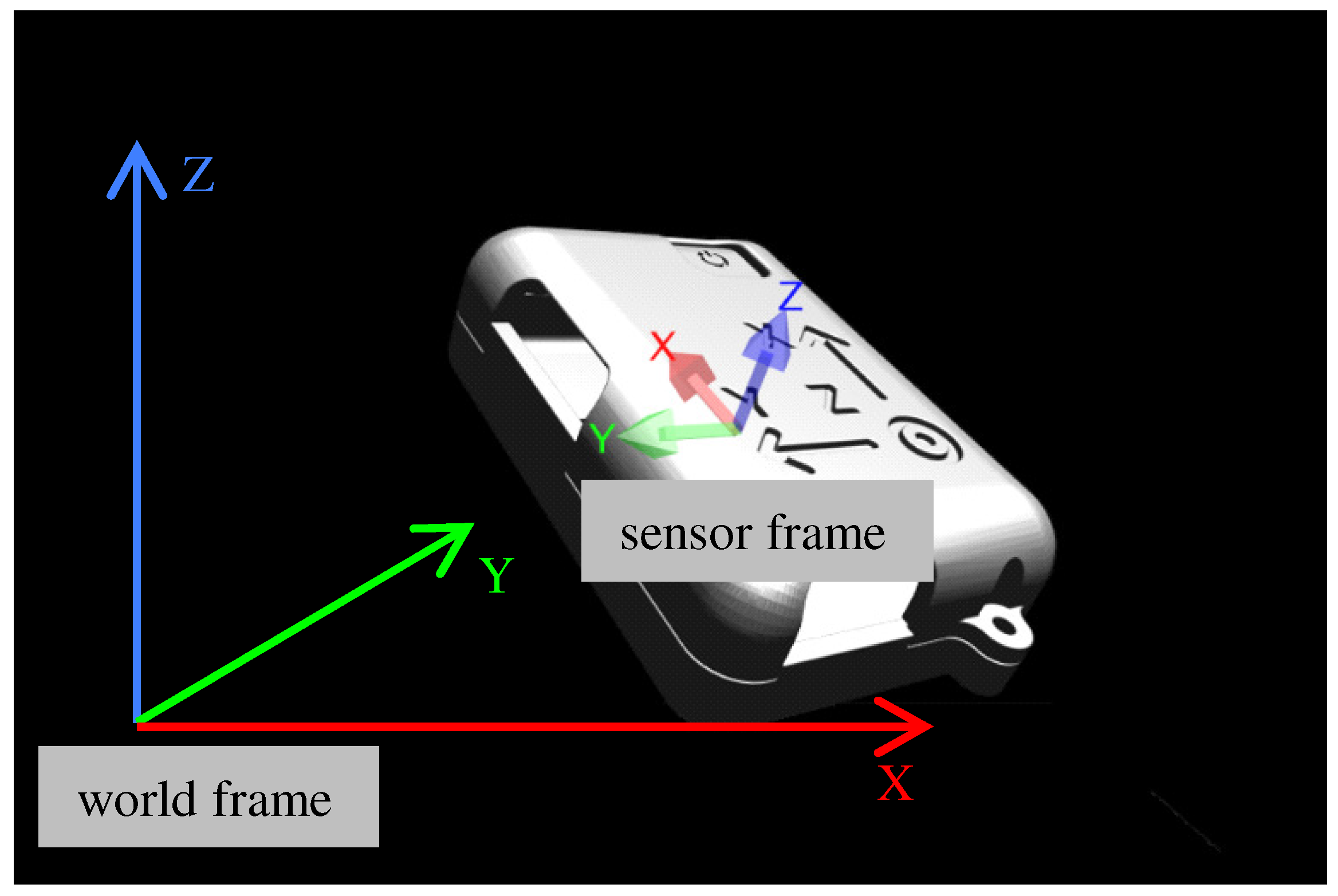
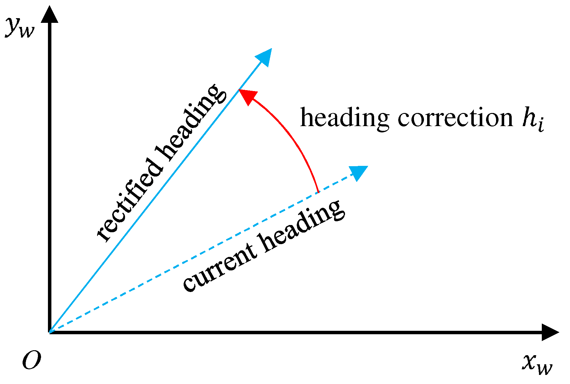
3.1. Orientation Update
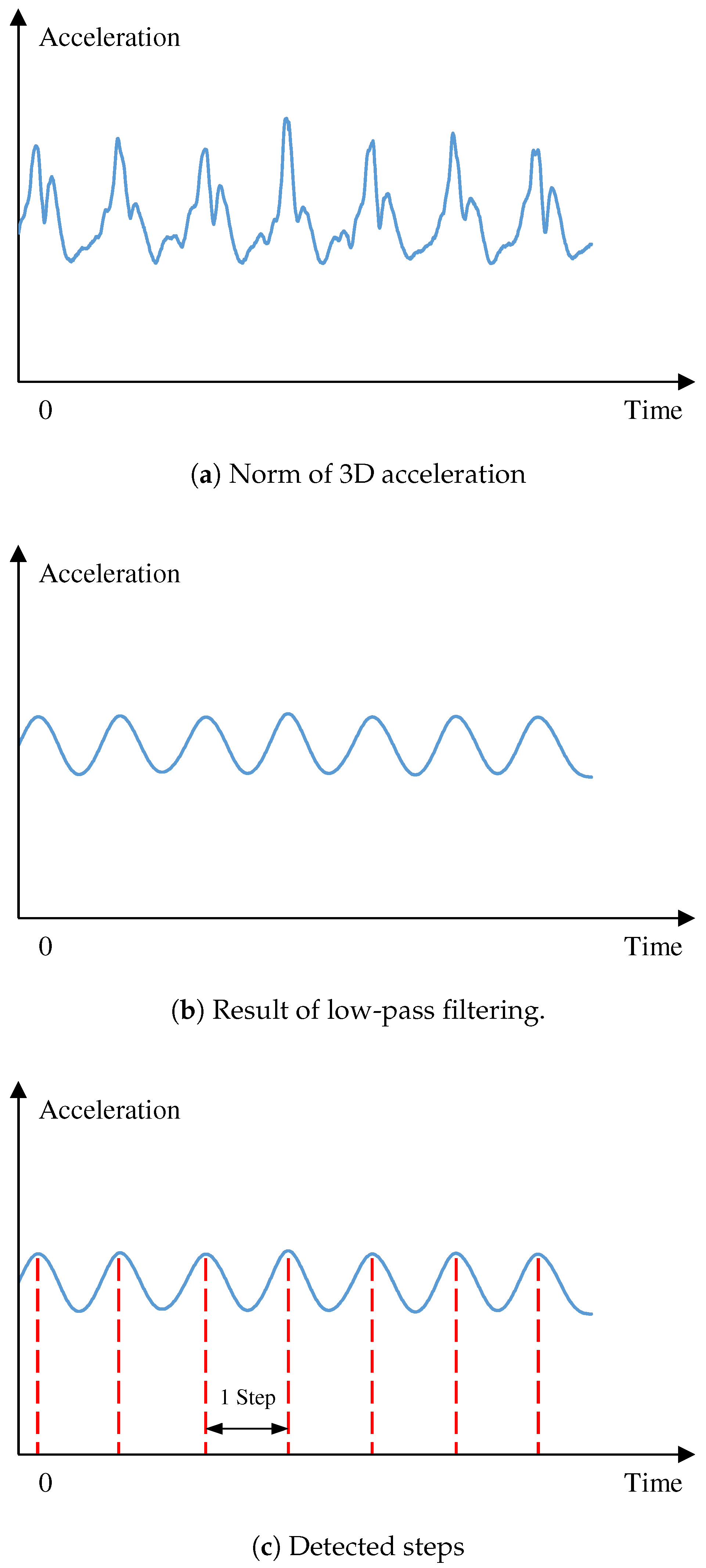
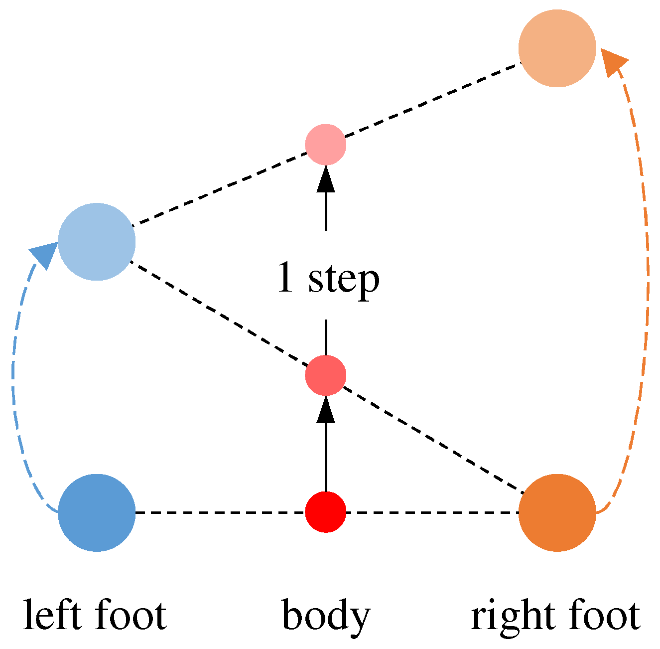
3.2. Step Detection
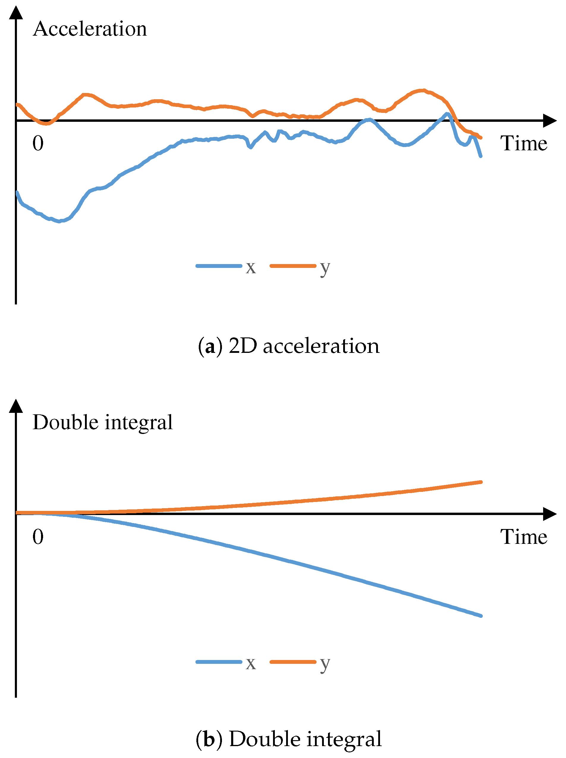
3.3. Step-Length Estimation
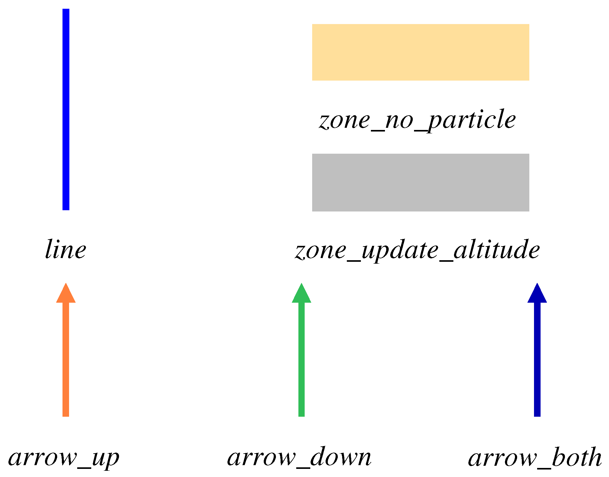
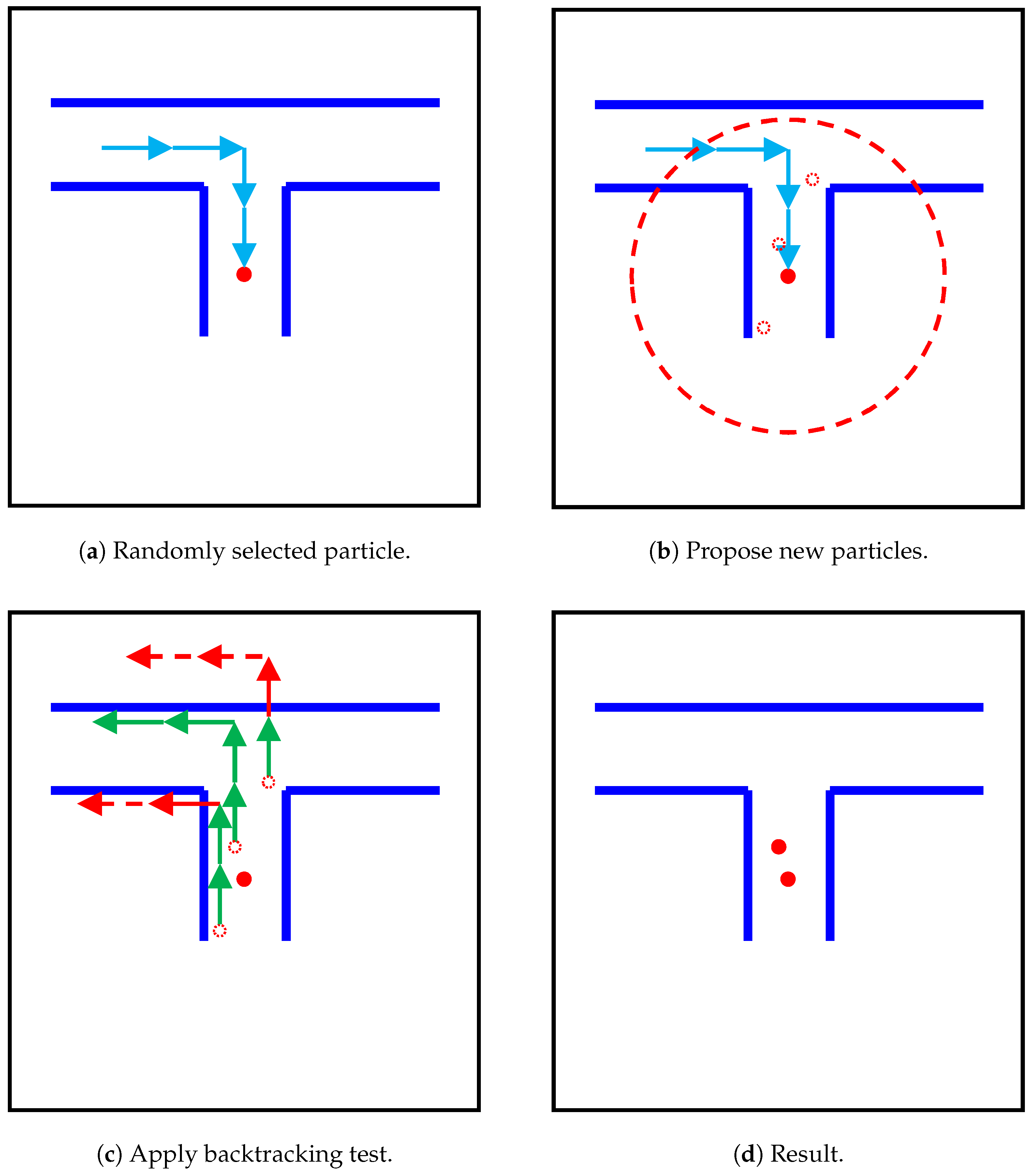
3.4. Map Matching
| Algorithm 1: Generating new particles. |
| while : |
| while : |
| if : |
| break |
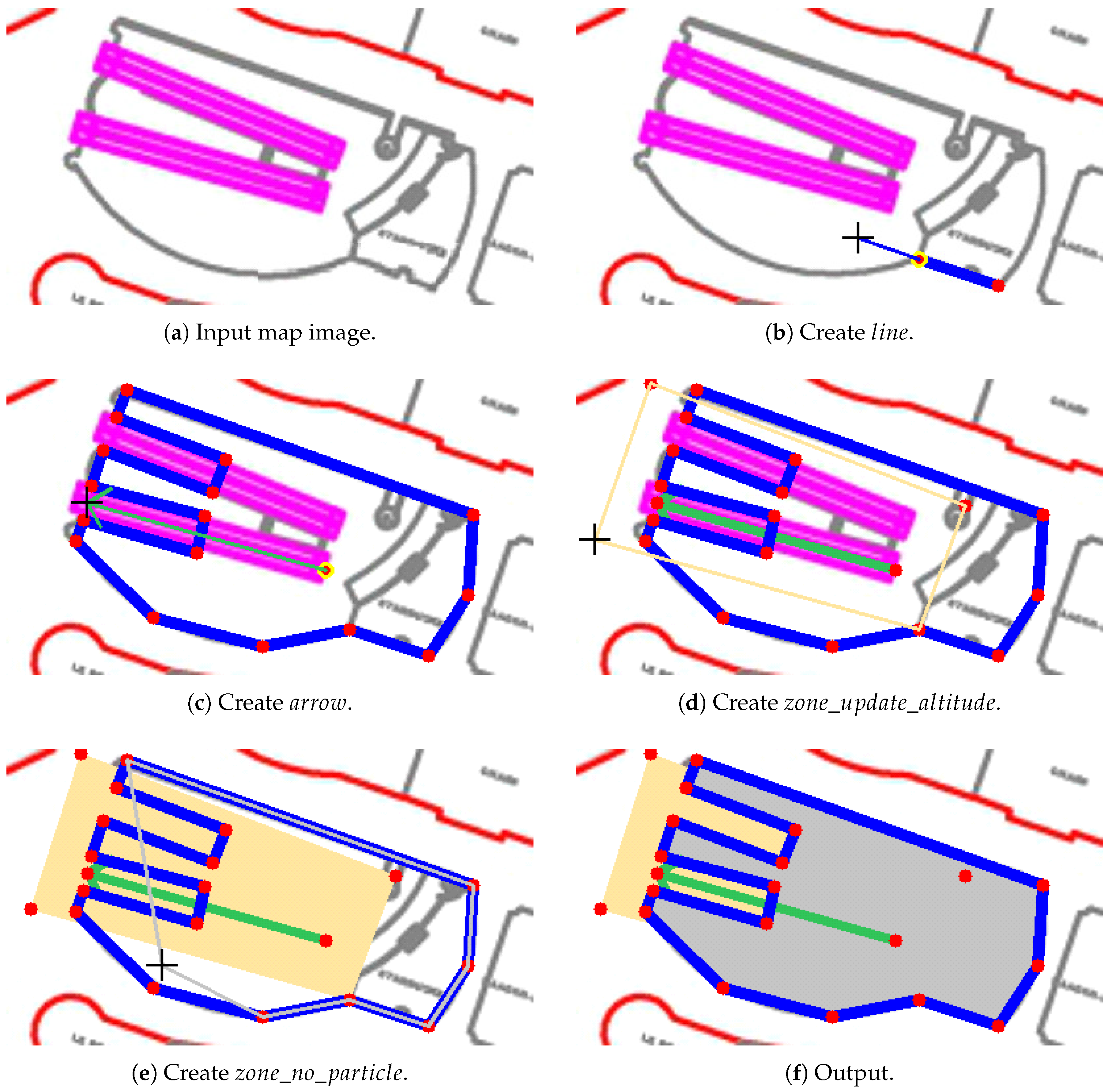
3.5. Map Editor
4. Evaluation
4.1. Evaluation Criterion
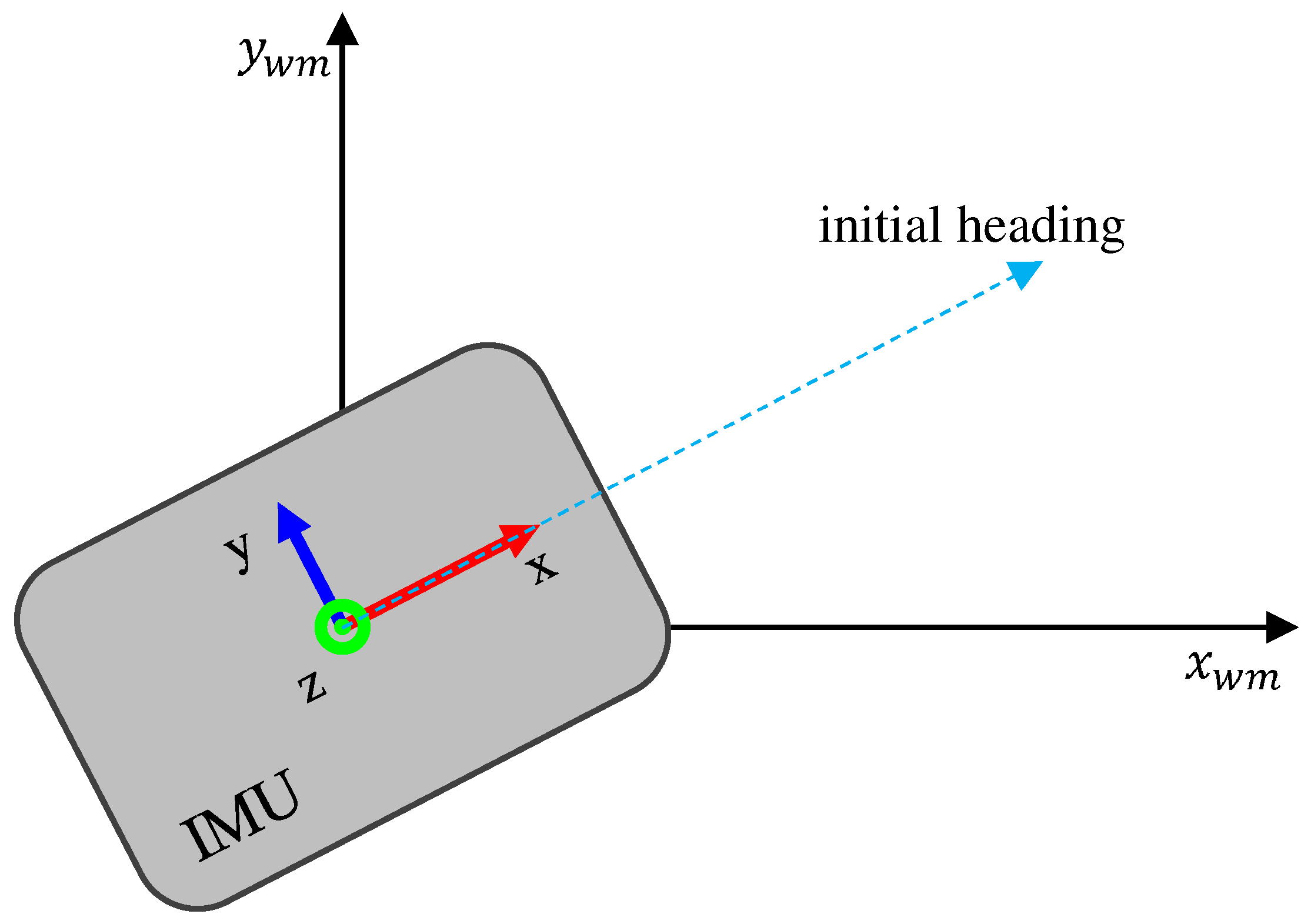
4.2. System Initialization
- Open the IMU, launch our system software, and connect the IMU to the computer.
- Calibrate the IMU pose with the known initial heading in the world frame of the map, as illustrated in Figure 12.
- Attach the IMU on the pedestrian chest, and run the system.
4.3. Lab Experiment
4.4. IPIN 2018 Competition Experiment
5. Conclusions
Author Contributions
Funding
Conflicts of Interest
References
- Finkenzeller, K. RFID Handbook: Fundamentals and Applications in Contactless Smart Cards, Radio Frequency Identification and Near-Field Communication; John Wiley & Sons: Hoboken, NJ, USA, 2010. [Google Scholar]
- Ni, L.M.; Liu, Y.; Lau, Y.C.; Patil, A.P. LANDMARC: indoor location sensing using active RFID. In Proceedings of the First IEEE International Conference on Pervasive Computing and Communications, Fort Worth, TX, USA, 26–26 March 2003; pp. 407–415. [Google Scholar]
- Newman, N. Apple iBeacon technology briefing. J. Direct Data Digit. Mark. Pract. 2014, 15, 222–225. [Google Scholar] [CrossRef] [Green Version]
- Yang, C.; Shao, H.R. WiFi-based indoor positioning. IEEE Commun. Mag. 2015, 53, 150–157. [Google Scholar] [CrossRef]
- Woo, S.; Jeong, S.; Mok, E.; Xia, L.; Choi, C.; Pyeon, M.; Heo, J. Application of WiFi-based indoor positioning system for labor tracking at construction sites: A case study in Guangzhou MTR. Autom. Constr. 2011, 20, 3–13. [Google Scholar] [CrossRef]
- Jimenez, A.R.; Seco, F.; Prieto, C.; Guevara, J. A comparison of pedestrian dead-reckoning algorithms using a low-cost MEMS IMU. In Proceedings of the 2009 IEEE International Symposium on Intelligent Signal Processing, Budapest, Hungary, 26–28 August 2009; pp. 37–42. [Google Scholar]
- Ojeda, L.; Borenstein, J. Non-GPS navigation for security personnel and first responders. J. Navig. 2007, 60, 391–407. [Google Scholar] [CrossRef]
- Ojeda, L.; Borenstein, J. Personal dead-reckoning system for GPS-denied environments. In Proceedings of the 2007 IEEE International Workshop on Safety, Security and Rescue Robotics, Rome, Italy, 27–29 September 2007; pp. 1–6. [Google Scholar]
- Antigny, N.; Servières, M.; Renaudin, V. Pedestrian Track Estimation with Handheld Monocular Camera and Inertial-Magnetic Sensor for Urban Augmented Reality. In Proceedings of the 2017 International Conference on Indoor Positioning and Indoor Navigation (IPIN), Sapporo, Japan, 18–21 September 2017. [Google Scholar]
- Zhang, Y.; Hu, W.; Xu, W.; Wen, H.; Chou, C.T. NaviGlass: Indoor Localisation Using Smart Glasses. In Proceedings of the 2016 International Conference on Embedded Wireless Systems and Networks, EWSN, Graz, Austria, 15–17 February 2016; pp. 205–216. [Google Scholar]
- Yan, H.; Shan, Q.; Furukawa, Y. RIDI: Robust IMU Double Integration. arXiv, 2017; arXiv:1712.09004. [Google Scholar]
- Elhoushi, M.; Georgy, J.; Korenberg, M.; Noureldin, A. Robust motion mode recognition for portable navigation independent on device usage. In Proceedings of the Position, Location and Navigation Symposium-PLANS 2014, Monterey, CA, USA, 5–8 May 2014; pp. 158–163. [Google Scholar]
- Quddus, M.A.; Ochieng, W.Y.; Noland, R.B. Current map-matching algorithms for transport applications: State-of-the art and future research directions. Transp. Res. Part C Emerg. Technol. 2007, 15, 312–328. [Google Scholar] [CrossRef] [Green Version]
- Shen, C.; Yang, J.; Tang, J.; Liu, J.; Cao, H. Note: Parallel processing algorithm of temperature and noise error for micro-electro-mechanical system gyroscope based on variational mode decomposition and augmented nonlinear differentiator. Rev. Sci. Instrum. 2018, 89, 076107. [Google Scholar] [CrossRef] [PubMed]
- Algrain, M.C.; Ehlers, D.E. Novel Kalman filtering method for the suppression of gyroscope noise effects in pointing and tracking systems. Opt. Eng. 1995, 34, 3016–3031. [Google Scholar] [CrossRef]
- Lo, P.H.; Halatyn, P.; Geoca, E.; Archibald, J.B. Gyroscope Noise Reduction and Drift Compensation. U.S. Patent 5,795,988, 18 August 1998. [Google Scholar]
- Chong, S.; Rui, S.; Jie, L.; Xiaoming, Z.; Jun, T.; Yunbo, S.; Jun, L.; Huiliang, C. Temperature drift modeling of MEMS gyroscope based on genetic-Elman neural network. Mech. Syst. Signal Process. 2016, 72, 897–905. [Google Scholar] [CrossRef]
- Madgwick, S.O.; Harrison, A.J.; Vaidyanathan, R. Estimation of IMU and MARG orientation using a gradient descent algorithm. In Proceedings of the 2011 IEEE International Conference on Rehabilitation Robotics, Zurich, Switzerland, 29 June–1 July 2011; pp. 1–7. [Google Scholar]
- Carberry, J.; Hinchly, G.; Buckerfield, J.; Tayler, E.; Burton, T.; Madgwick, S.; Vaidyanathan, R. Parametric design of an active ankle foot orthosis with passive compliance. In Proceedings of the 2011 24th International Symposium on Computer-Based Medical Systems (CBMS), Bristol, UK, 27–30 June 2011; pp. 1–6. [Google Scholar]
- Susi, M.; Renaudin, V.; Lachapelle, G. Motion mode recognition and step detection algorithms for mobile phone users. Sensors 2013, 13, 1539–1562. [Google Scholar] [CrossRef] [PubMed]
- Weinberg, H. Using the ADXL202 in pedometer and personal navigation applications. Analog Devices AN-602 Appl. Note 2002, 2, 1–6. [Google Scholar]
- Shin, S.; Park, C.; Kim, J.; Hong, H.; Lee, J. Adaptive step length estimation algorithm using low-cost MEMS inertial sensors. In Proceedings of the Sensors Applications Symposium, San Diego, CA, USA, 6–8 February 2007; pp. 1–5. [Google Scholar]
- Renaudin, V.; Susi, M.; Lachapelle, G. Step length estimation using handheld inertial sensors. Sensors 2012, 12, 8507–8525. [Google Scholar] [CrossRef] [PubMed]
- Ristic, B.; Arulampalam, S.; Gordon, N. Beyond the Kalman Filter: Particle Filters for Tracking Applications; Artech House: Norwood, MA, USA, 2003. [Google Scholar]
- Xiao, Z.; Wen, H.; Markham, A.; Trigoni, N. Lightweight map matching for indoor localisation using conditional random fields. In Proceedings of the 13th International Symposium on Information Processing in Sensor Networks, Berlin, Germany, 15–17 April 2014; pp. 131–142. [Google Scholar]
- Shin, S.H.; Park, C.G.; Choi, S. New Map-Matching Algorithm Using Virtual Track for Pedestrian Dead Reckoning. ETRI J. 2010, 32, 891–900. [Google Scholar] [CrossRef]
- Arulampalam, M.S.; Maskell, S.; Gordon, N.; Clapp, T. A tutorial on particle filters for online nonlinear/non-Gaussian Bayesian tracking. IEEE Trans. Signal Process. 2002, 50, 174–188. [Google Scholar] [CrossRef] [Green Version]
- Davidson, P.; Collin, J.; Takala, J. Application of particle filters for indoor positioning using floor plans. In Proceedings of the Ubiquitous Positioning Indoor Navigation and Location Based Service (UPINLBS), Kirkkonummi, Finland, 14–15 October 2010; pp. 1–4. [Google Scholar]
- Klepal, M.; Beauregard, S.; Widyawan. A backtracking particle filter for fusing building plans with PDR displacement estimates. In Proceedings of the 2008 5th Workshop on Positioning, Navigation and Communication, Hannover, Germany, 27 March 2008; pp. 207–212. [Google Scholar]
- Bojja, J.; Kirkko-Jaakkola, M.; Collin, J.; Takala, J. Indoor localization methods using dead reckoning and 3D map matching. J. Signal Process. Syst. 2014, 76, 301–312. [Google Scholar] [CrossRef]
- Klepal, M.; Beauregard, S.; Widyawan. A novel backtracking particle filter for pattern matching indoor localization. In Proceedings of the First ACM International Workshop on Mobile Entity Localization and Tracking in GPS-Less Environments, Orlando, FL, USA, 30 September 2008; pp. 79–84. [Google Scholar]


| Range | Resolution | Sampling Rate | |
|---|---|---|---|
| Accelerometer | g | 490 g | 400 Hz |
| Gyroscope | /s | /s | 400 Hz |
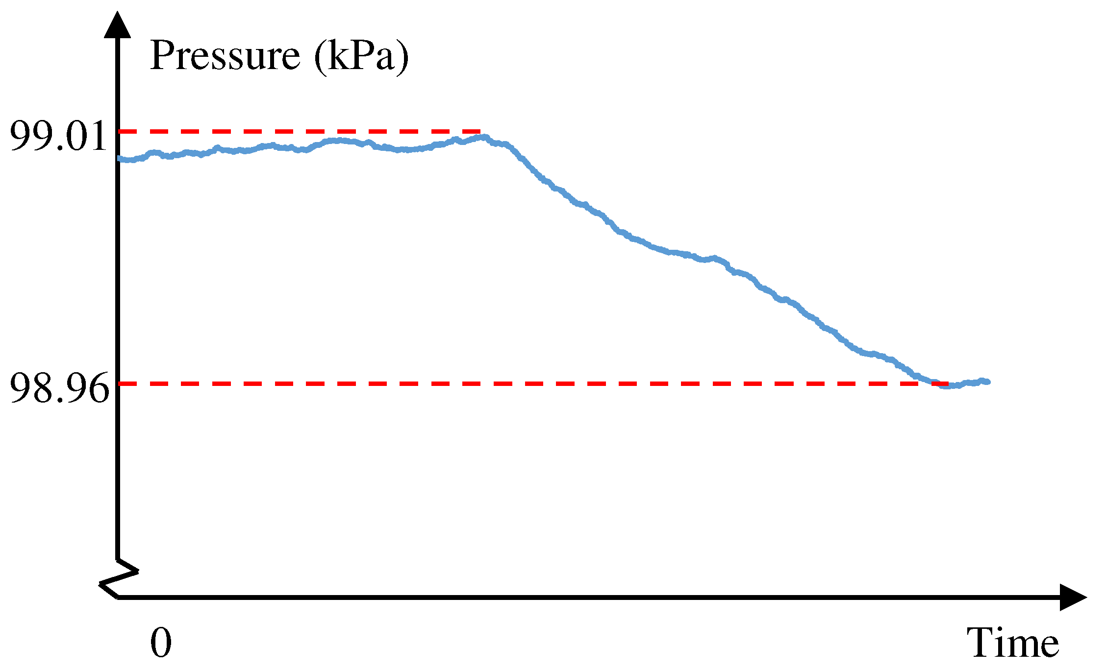
| Barometer | kPa | Pa | 25 Hz |
| Size | 56 × 39 × 18 mm | ||
| Weight | 46 g |
| Maximal number of particles in our system. | |
| Number of current existing particles. | |
| n | Number of existing particles before generating new particles. |
| Maximal trying time on proposing a new particle. | |
| Counter of trying time on proposing a new particle. | |
| Randomly selected particle. | |
| Second input parameter of function . | |
| Randomly select one particle from existing particles and return it. | |
| Propose a new particle around and return it. | |
| Apply backtracking test to . Return if passed the test. | |
| Append to existing particles. |
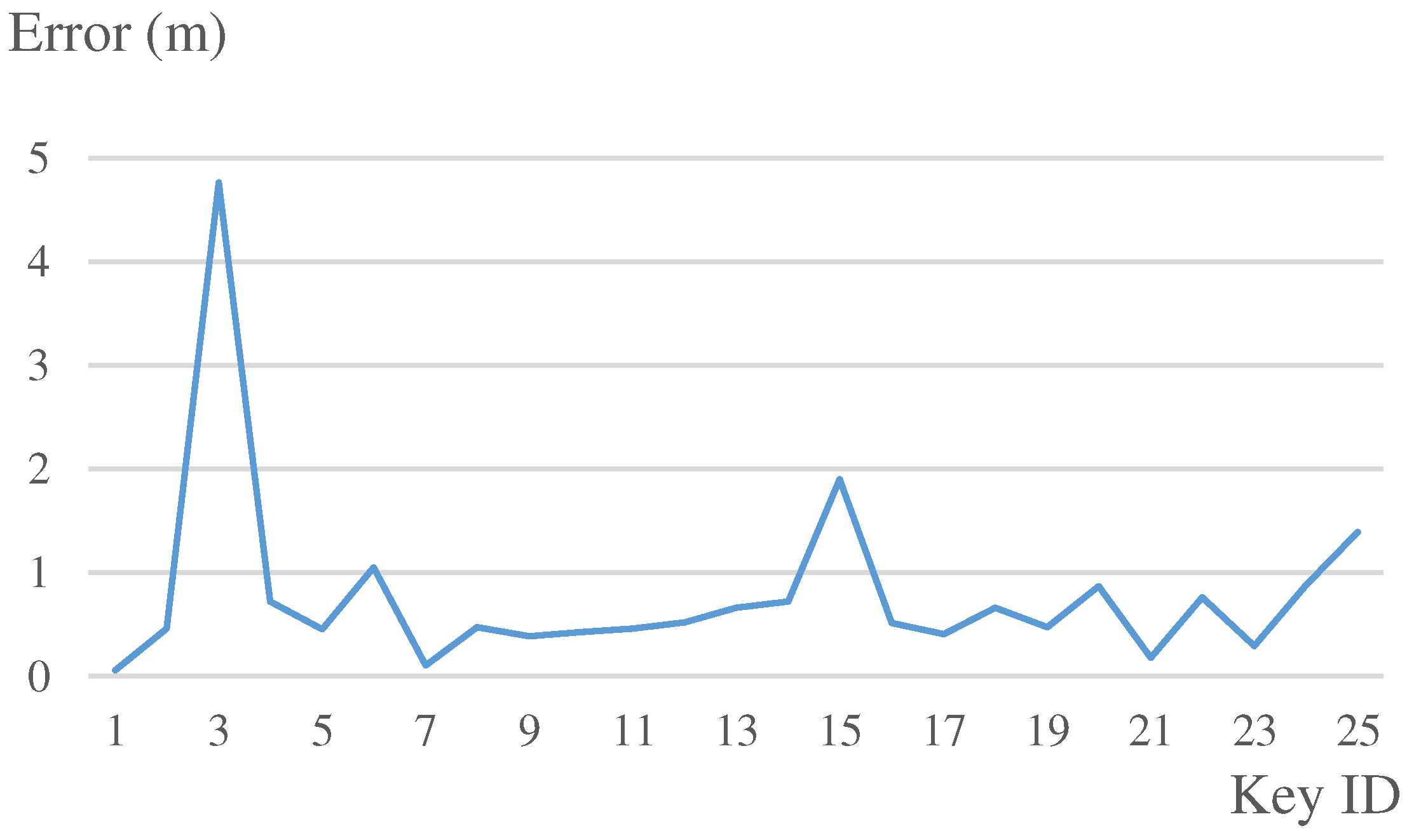
| Travelled distance: 432.22 m | |
|---|---|
| Total number of keypoints: 25 | |
| Our system | |
| Mean | 0.78 m |
| Median | 0.51 m |
| 75th percent | 0.76 m |
| Standard deviation | 0.92 m |
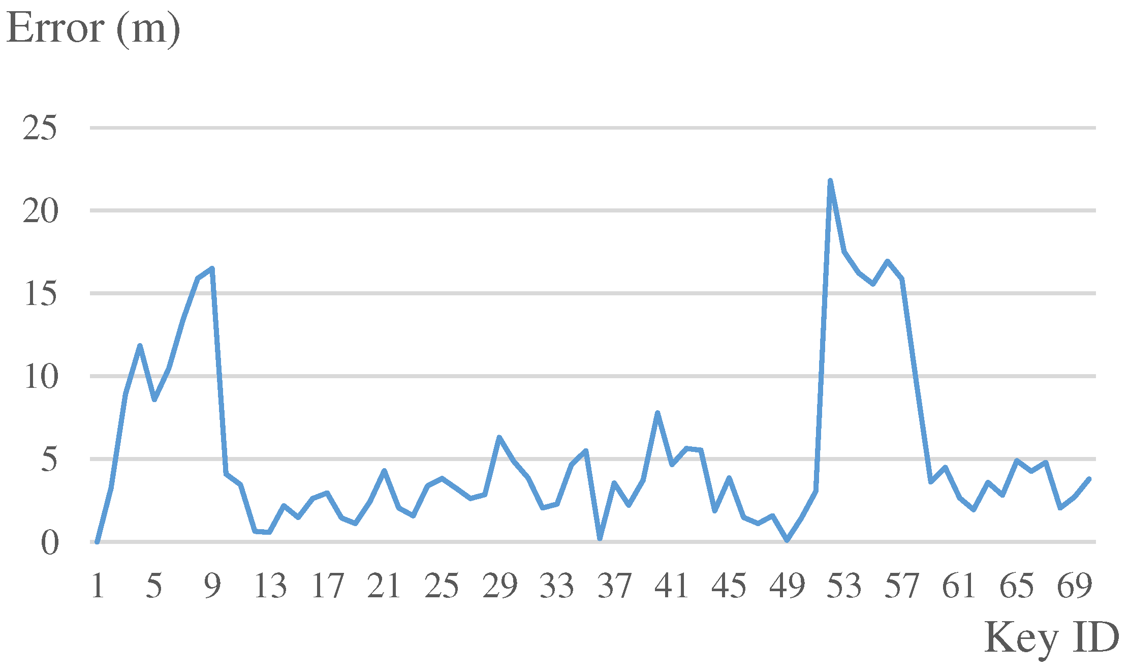
| Travelled distance: 792.49 m | |
|---|---|
| Keypoint number: 70 | |
| Our system | |
| Mean | 5.2 m |
| Median | 3.6 m |
| 75th percent | 5.7 m |
| Standard deviation | 5.0 m |
© 2019 by the authors. Licensee MDPI, Basel, Switzerland. This article is an open access article distributed under the terms and conditions of the Creative Commons Attribution (CC BY) license (http://creativecommons.org/licenses/by/4.0/).
Share and Cite
Lu, C.; Uchiyama, H.; Thomas, D.; Shimada, A.; Taniguchi, R.-i. Indoor Positioning System Based on Chest-Mounted IMU. Sensors 2019, 19, 420. https://doi.org/10.3390/s19020420
Lu C, Uchiyama H, Thomas D, Shimada A, Taniguchi R-i. Indoor Positioning System Based on Chest-Mounted IMU. Sensors. 2019; 19(2):420. https://doi.org/10.3390/s19020420
Chicago/Turabian StyleLu, Chuanhua, Hideaki Uchiyama, Diego Thomas, Atsushi Shimada, and Rin-ichiro Taniguchi. 2019. "Indoor Positioning System Based on Chest-Mounted IMU" Sensors 19, no. 2: 420. https://doi.org/10.3390/s19020420