Vertical-Strip-Fed Broadband Circularly Polarized Dielectric Resonator Antenna


Abstract
:1. Introduction
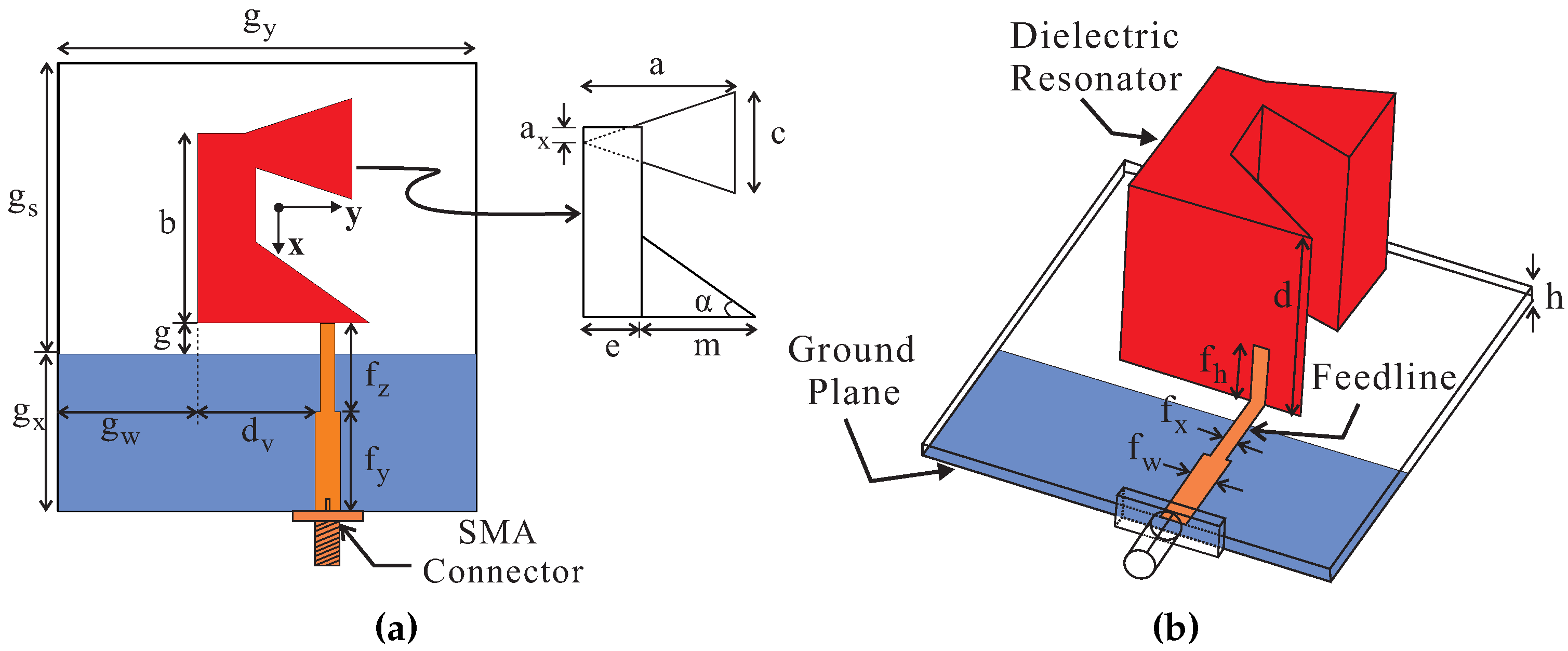
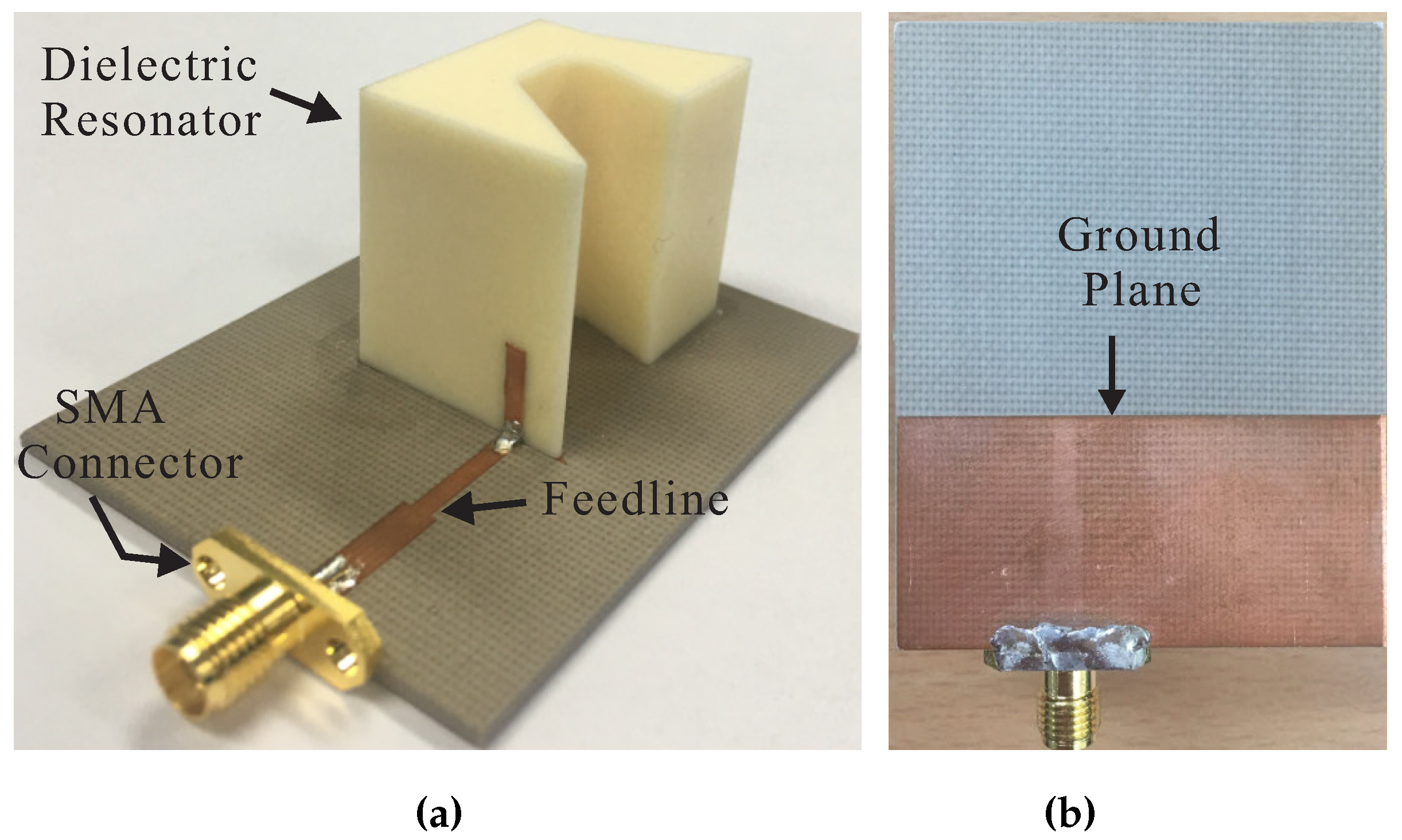
2. Antenna Design
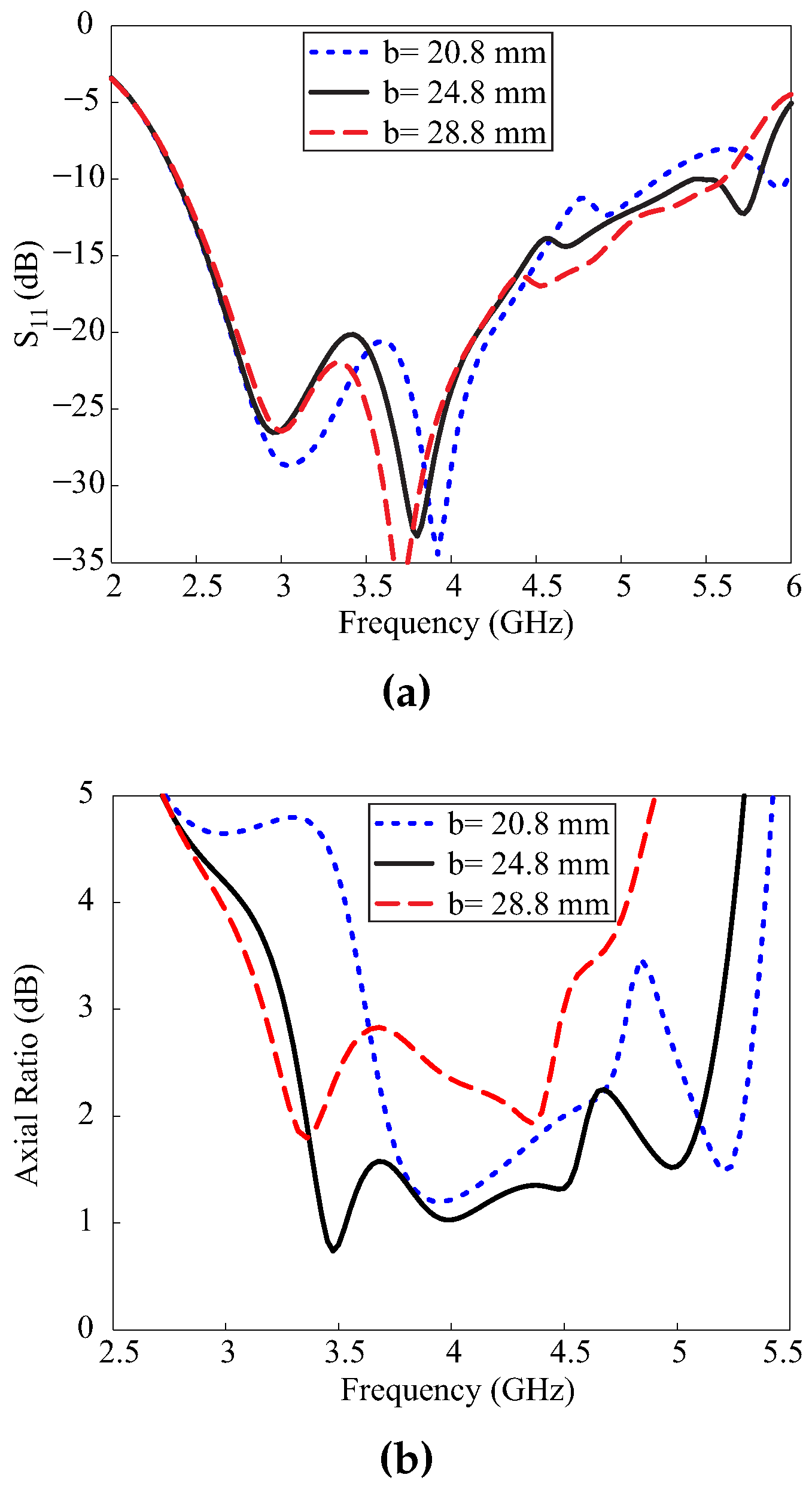
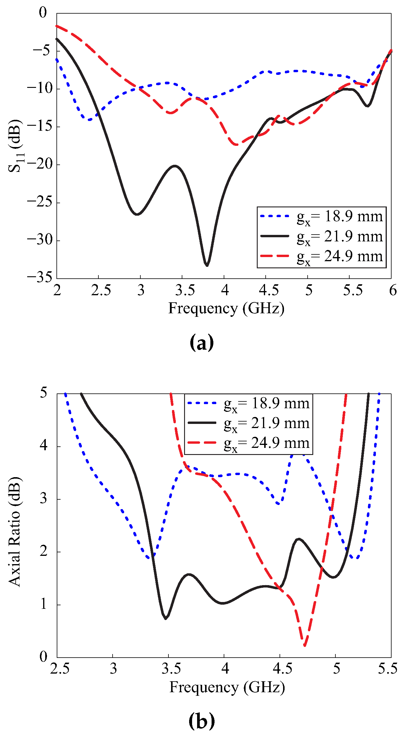
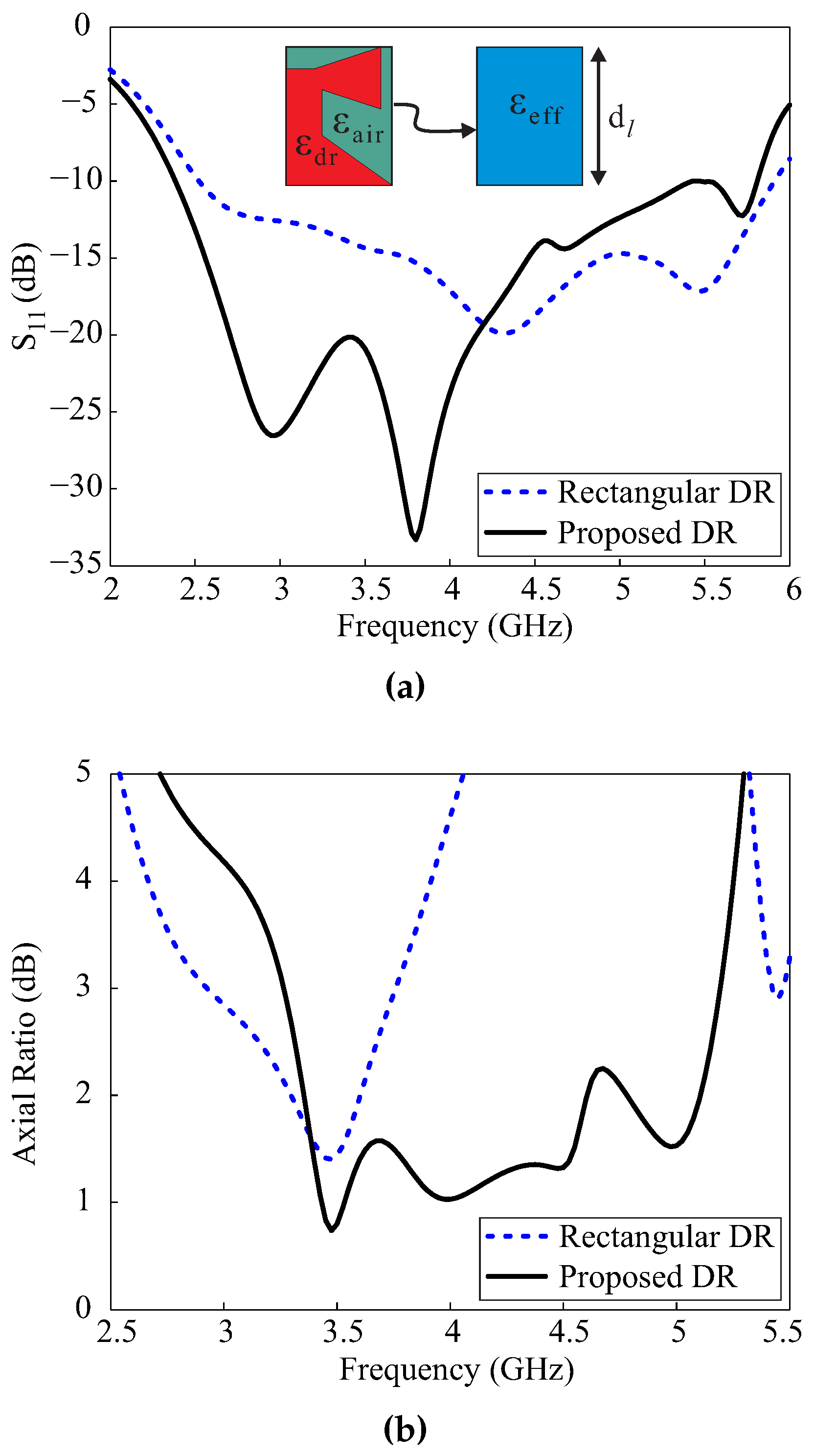
3. Parametric Analysis
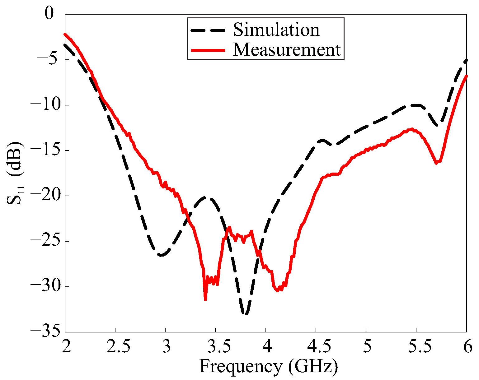
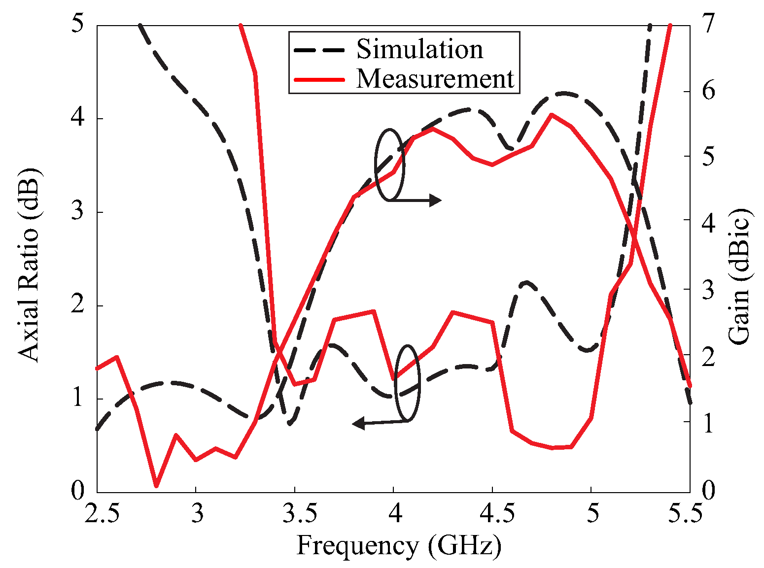
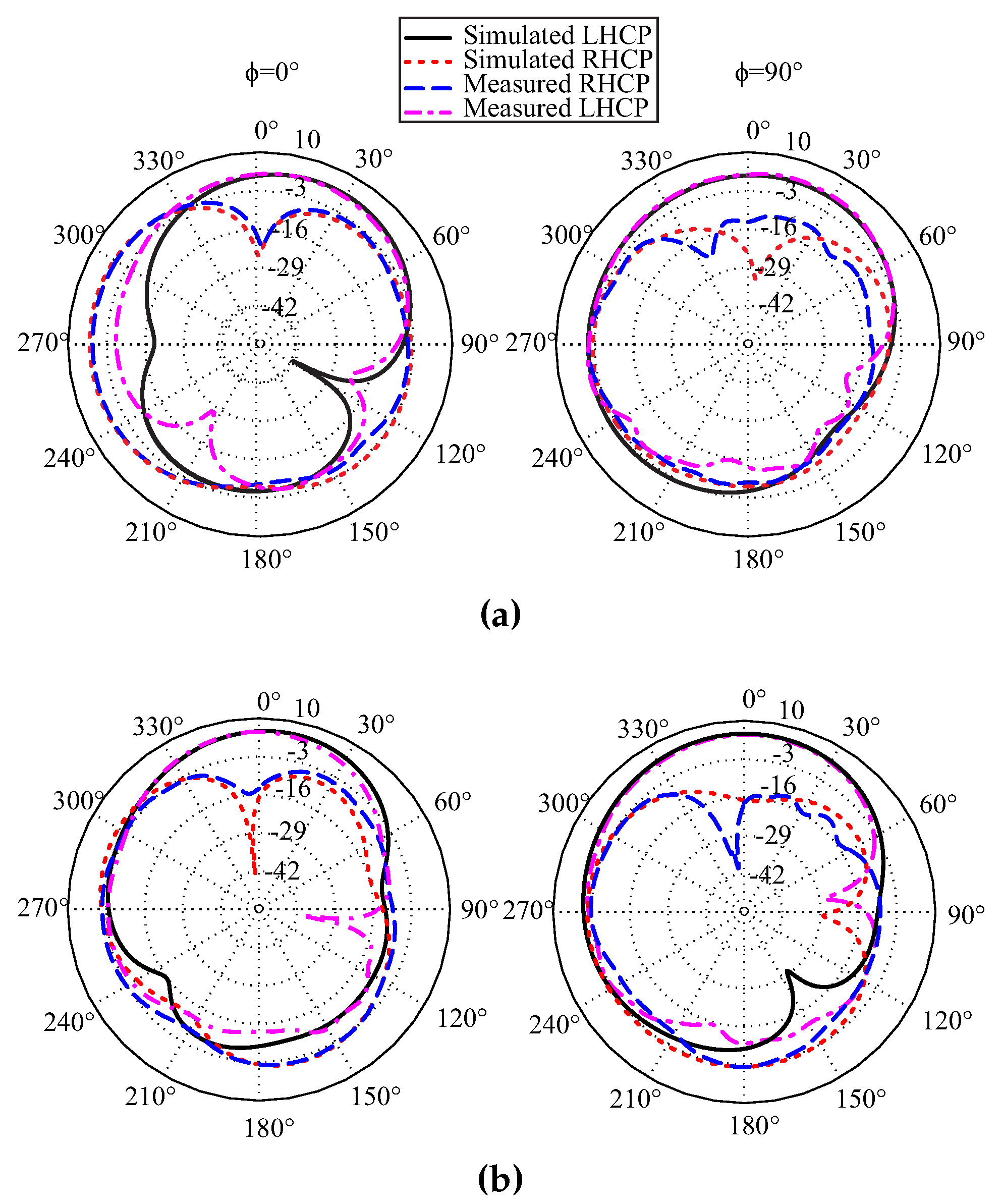
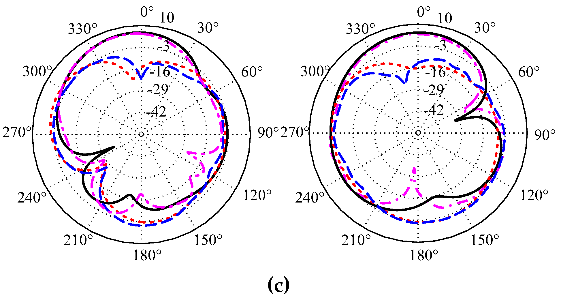
4. Measurement Results and Discussion
5. Conclusions
Acknowledgments
Author Contributions
Conflicts of Interest
References
- Gao, S.; Luo, Q.; Zhu, F. Circularly Polarized Antennas; Wiley: West Sussex, UK, 2014. [Google Scholar]
- Leung, K.W.; Mok, S.K. Circularly polarised dielectric resonator antenna excited by perturbed annular slot with backing cavity. Electron. Lett. 2001, 37, 934–936. [Google Scholar] [CrossRef]
- Lee, J.M.; Kim, S.-J.; Kwon, G.; Song, C.M.; Yang, Y.; Lee, K.-Y.; Hwang, K.C. Circularly polarized semi-eccentric annular dielectric resonator antenna for X-band applications. IEEE Antennas Wirel. Propag. Lett. 2015, 14, 1810–1813. [Google Scholar] [CrossRef]
- Altaf, A.; Yang, Y.; Lee, K.-Y.; Hwang, K.C. Circularly polarized Spidron fractal dielectric resonator antenna. IEEE Antennas Wirel. Propag. Lett. 2015, 14, 1806–1809. [Google Scholar] [CrossRef]
- Lee, J.M.; Kwon, G.; Song, C.M.; Lee, K.-Y.; Yang, Y.; Hwang, K.C. Wideband circularly polarized Spidron fractal slot antenna with a grooved dielectric resonator. J. Electromagn. Waves Appl. 2015, 29, 1942–1951. [Google Scholar] [CrossRef]
- Zou, M.; Pan, J. Wideband hybrid circularly polarised rectangular dielectric resonator antenna excited by modified cross-slot. Electron. Lett. 2014, 50, 1123–1125. [Google Scholar] [CrossRef]
- Trinh-Van, S.; Yang, Y.; Lee, K.-Y.; Hwang, K.C. A wideband circularly polarized pixelated dielectric resonator antenna. Sensors 2016, 16, 1349. [Google Scholar] [CrossRef] [PubMed]
- Trinh-Van, S.; Yang, Y.; Lee, K.-Y.; Hwang, K.C. A wideband circularly polarized antenna with a multiple-circular-sector dielectric resonator. Sensors 2016, 16, 1849. [Google Scholar] [CrossRef] [PubMed]
- Pan, Y.; Leung, K.W. Wideband circularly polarized trapezoidal dielectric resonator antenna. IEEE Antennas Wirel. Propag. Lett. 2010, 9, 588–591. [Google Scholar]
- Kumar, R.; Chaudhary, R.K. A wideband circularly polarized cubic dielectric resonator antenna excited with modified microstrip feed. IEEE Antennas Wirel. Propag. Lett. 2016, 15, 1285–1288. [Google Scholar] [CrossRef]
- Khalily, M.; Kamarudin, M.R.; Jamaluddin, M.H. A novel square dielectric resonator antenna with two unequal inclined slits for wideband circular polarization. IEEE Antennas Wirel. Propag. Lett. 2013, 12, 1256–1259. [Google Scholar] [CrossRef]
- Fakhte, S.; Oraizi, H.; Karimian, R. A novel low-cost circularly polarized rotated stacked dielectric resonator antenna. IEEE Antennas Wirel. Propag. Lett. 2014, 13, 722–725. [Google Scholar] [CrossRef]


| Parameters | Values | Parameters | Values |
|---|---|---|---|
| 35.40 | 15.35 mm | ||
| 20.20 mm | 9.00 mm | ||
| 24.80 mm | 3.30 mm | ||
| 13.20 mm | 13.00 mm | ||
| 25.60 mm | 1.90 mm | ||
| 7.60 mm | 11.50 mm | ||
| 2.60 mm | 36.10 mm | ||
| 1.52 mm | 13.25 mm | ||
| 14.90 mm | 21.90 mm | ||
| 2.00 mm | 46.00 mm |
| Structure | Description | −10 dB Reflection Bandwidth (GHz) | 3 dB ARBW (GHz) | Dimensions () | Peak Gain (dBic) |
|---|---|---|---|---|---|
| [7] | CP DRA using a pixelated DR | 2.62–3.63 (32.3%) | 2.85–3.3 (14.6%) | 1.44 × 1.44 × 0.34 | 6.13 |
| [8] | CP DRA using a multi-circular-sector DR | 1.88–2.58 (31.4%) | 2.06-2.50 (19.3%) | 0.84 × 0.84 × 0.39 | 7.65 |
| [9] | CP DRA using a trapezoidal DR | 2.88–4.04 (33.5%) | 3.11–3.86 (21.5%) | 1.16 × 1.16 × 0.44 | 8.39 |
| [10] | CP DRA excited with a modified microstrip feed | 2.62–3.63 (33.4%) | 2.95–3.63 (20.6%) | 0.44 × 0.44 × 0.21 | 1.51 |
| [11] | CP DRA using a square DR with two unequal inclined slits | 3.08–5.18 (50.8%) | 3.08–4.43 (36%) | 0.59 × 0.59 × 0.11 | 6 |
| Proposed work | CP DRA using the proposed DR | 2.44–5.88 (82.7%) | 3.35–5.25 (44.2%) | 0.66 × 0.83 × 0.39 | 5.66 |
© 2017 by the authors. Licensee MDPI, Basel, Switzerland. This article is an open access article distributed under the terms and conditions of the Creative Commons Attribution (CC BY) license (http://creativecommons.org/licenses/by/4.0/).
Share and Cite
Altaf, A.; Jung, J.-W.; Yang, Y.; Lee, K.-Y.; Hwang, K.C. Vertical-Strip-Fed Broadband Circularly Polarized Dielectric Resonator Antenna. Sensors 2017, 17, 1911. https://doi.org/10.3390/s17081911
Altaf A, Jung J-W, Yang Y, Lee K-Y, Hwang KC. Vertical-Strip-Fed Broadband Circularly Polarized Dielectric Resonator Antenna. Sensors. 2017; 17(8):1911. https://doi.org/10.3390/s17081911
Chicago/Turabian StyleAltaf, Amir, Jin-Woo Jung, Youngoo Yang, Kang-Yoon Lee, and Keum Cheol Hwang. 2017. "Vertical-Strip-Fed Broadband Circularly Polarized Dielectric Resonator Antenna" Sensors 17, no. 8: 1911. https://doi.org/10.3390/s17081911