1. Introduction
Structural Health Monitoring (SHM) systems are automated tools, aimed at rapidly identifying the onset of structural damage and at tracking the condition of structures during forced or natural excitation [
1]. Current SHM systems almost adopt Non-Destructive Testing (NDT) techniques, which can be divided into two types: on-demand type and in situ. The on-demand NDT techniques are based on instrumentation brought to the measurement site on-demand, including X-ray, infrared thermography, laser scanning and microwave radar [
2,
3,
4,
5]. However, these techniques cannot measure the physical quantities of concrete directly and the measured results are not real-time. The second family is based on the deployment of several local sensors permanently coupled with structural elements. The in situ techniques can also be divided into two groups, according to the use of wired or wireless technology. Among the wired ones [
6,
7], high measuring precision, great resolution, and real time monitoring can be obtained, however they are quite time-consuming and expensive because of the complicated manufacturing as well as the extensive signal processing.
Thanks to fast and easy installation, wireless sensors are gaining a growing interest. Most of the wireless sensors for SHM are based on Wireless Sensor Networks (WSN), which are battery-powered and permit long-range operating [
8,
9]. However, once these wireless sensors are immersed in concrete, their batteries cannot be replaced again and their lifespan are limited to several years. Furthermore, their cost and complexity are still relatively high. Recently, with the rapid development of Radio Frequency Identification (RFID) technology, the wireless sensors based on passive RFID technology have aroused great interest [
10]. The passive tag is able to passively communicate with the interrogator on a zero-powered backscatter mechanism, resulting in simple architecture, low power, and low cost. The passive RFID sensors are excellent choices for long-term and low-cost SHM [
11,
12].
Humidity is one of the parameters considered as a critical factor in the progress of cement maturity by influencing the stability, the transformation of hydrates, and strength development [
13]. The result of this process is an increased strength and decreased permeability. Uncontrolled moisture diffusion during the setting and curing process can cause a number of detrimental effects. For example, fast moisture diffusion resulting from high temperature during curing, may lead to higher shrinkage stresses and lower long-term concrete strength [
14,
15]. An insufficient water supply due to this diffusion and the evaporation of the internal moisture will hinder the hydration of cement [
16]. Besides, during the process of casting reinforced concrete, the corrosion of steel reinforcing bars due to high humidity will decrease the service life of reinforced concrete structures [
17]. Therefore, humidity monitoring is significant for concrete.
There are various kinds of RFID-based humidity sensors. The simplest kind is the chipless RFID temperature sensor, which requires no Integrated Circuits (ICs) and transmits sensor data by changing the radar cross section of the RFID antenna [
18]. The characters of transmitting analog sensor data and no digital blocks lower its performances and constrain its applications mainly in low-cost fields. In situations where there are high accuracy requirements or a large number of sensors in close proximity, chip-based RFID sensors are employed to incorporate digital modulation. A humidity-to-frequency sensor in CMOS technology with wireless readout is presented in [
19], however this wireless humidity sensor only achieves a working range of 30 mm because of 13.56 MHz operating frequency. A wireless temperature and humidity sensors based on Ultra-High Frequency (UHF) is proposed in [
20]. Because of the complex architecture and off-chip humidity sensor, the wireless humidity sensing range in air is only 2.7 m, which cannot meet the tough requirements of concrete monitoring.
This paper presents a novel wireless humidity sensor for SHM. To our knowledge, this is the first work to measure the concrete humidity based on UHF RFID technology. The rest of the paper is organized as follows.
Section 2 analyzes electromagnetic wave transmission in concrete and proposes a novel architecture of wireless humidity sensor for ultra-low power application.
Section 3 presents the detailed design of key blocks.
Section 4 illustrates the measurement results and compared it with the results of traditional measurement. The conclusion is made in
Section 5.
2. System Design of Proposed Wireless Humidity Sensor
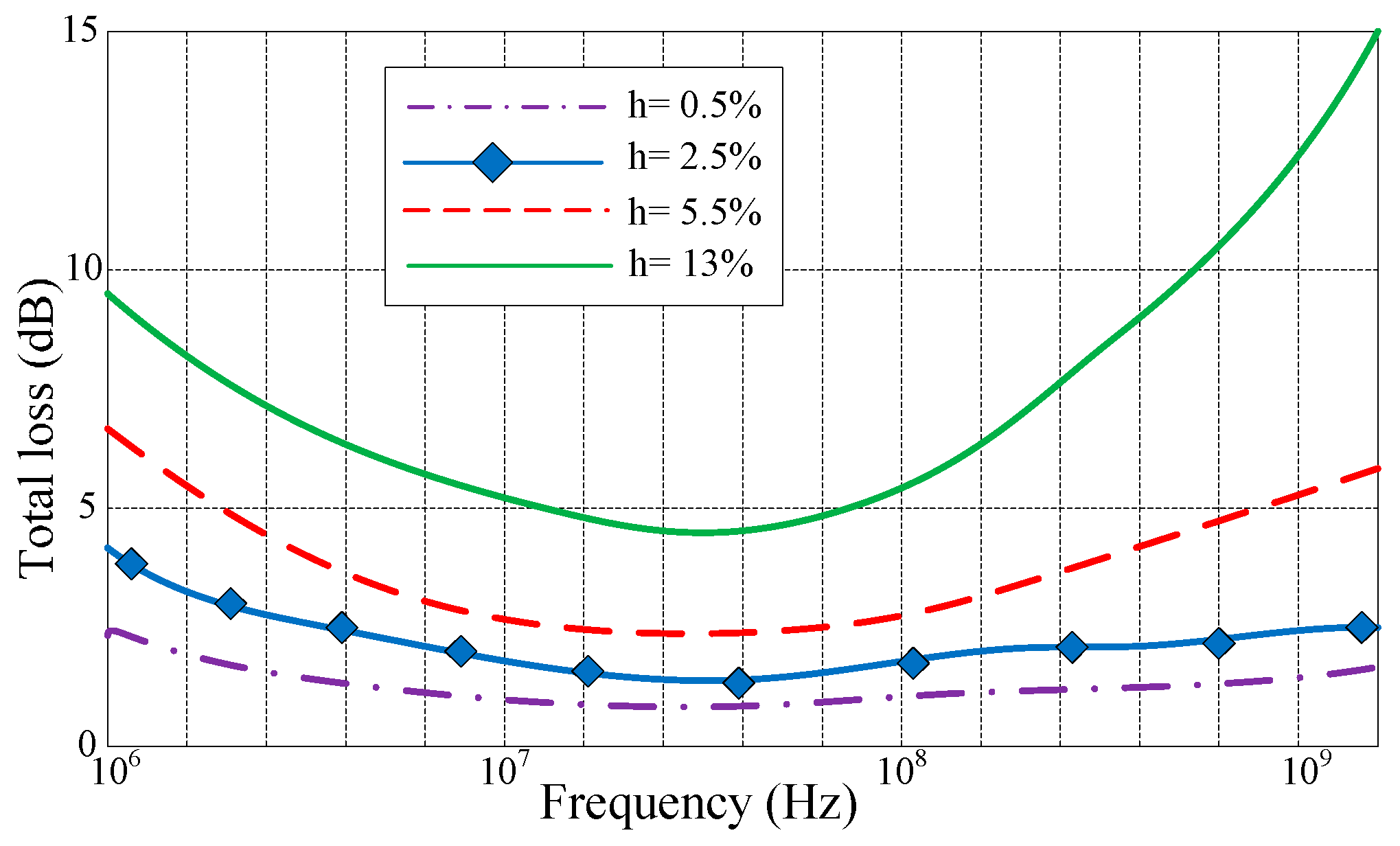
Since concrete has distinct electromagnetic properties at different humidity conditions, the total power loss for electromagnetic waves penetrating concrete are analyzed through the 1 MHz to 1 GHz frequency range for various humidity conditions (at depth of 0.2 m), i.e., 0.5%, 2.5%, 5.5%, and 13%. The matlab simulation results are shown in
Figure 1, which are calculated from the ratio of water to the volume of the specimen [
21,
22,
23]. As expected, due to the reverse variations of the transmission and propagation losses, an optimum frequency range exists, within which there is significantly smaller power loss. For example, the total loss in 20–80 MHz frequency range for wet concrete (13% humidity) is about 5 to 10 dB less than the total loss at either 1 MHz or 1 GHz. The proposed wireless sensor works at 915 MHz, the total loss is about 10 dB at 915 MHz, which is acceptable for concrete monitoring.
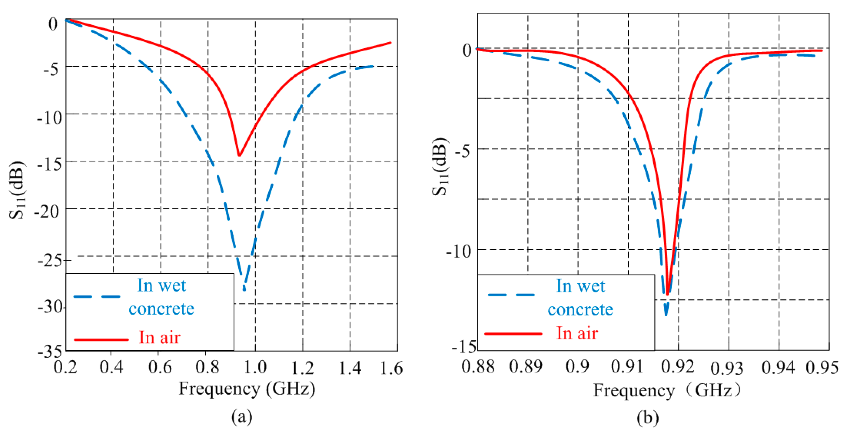
The aim of the proposed RFID sensor is to perform humidity measurement inside the concrete, thus the type of the antenna should be taken into consideration.
Figure 2 compares the return loss performances of the same RFID tag respectively equipped with two typical types of antenna (dipole and patch) in wet concrete and air. The results is based on the extended Debye model of concrete [
24] and simulated by HFSS. The two pairs of RFID tags, one residing in air and another one residing inside the concrete slab at 8 cm depth, are designed to resonate at 915 MHz. From
Figure 2a we can see the performance of dipole is dramatically affected when it is embedded in the concrete, the bandwidth is wider and the transmission loss increases obviously. However seen from
Figure 2b, the performance of patch antenna is less sensitive to the humidity change of concrete. Hence, the patch antenna is more suitable for concrete monitoring.
The theoretical practicable operating power of an RFID tag
Pt is calculated from the Friis transmission equation [
25]:
where
Er is the effective isotropic radiation power of a reader,
Ga is the tag antenna gain,
ηr is the RF-to-DC power conversion efficiency of the rectifier,
λ is the wavelength of the electromagnetic wave, and
d is the communication distance. From Equation (1), the communication distance
d can be expressed as:
Hence, in order to achieve longer communication distance, lower Pt and higher ηr are critical for the design of UHF RFID tag, for Er is limited by regional regulations (4 W is the maximum transmitted power) and Ga is roughly determined by the allowable antenna area (1.64 for the λ/2 dipole antenna).
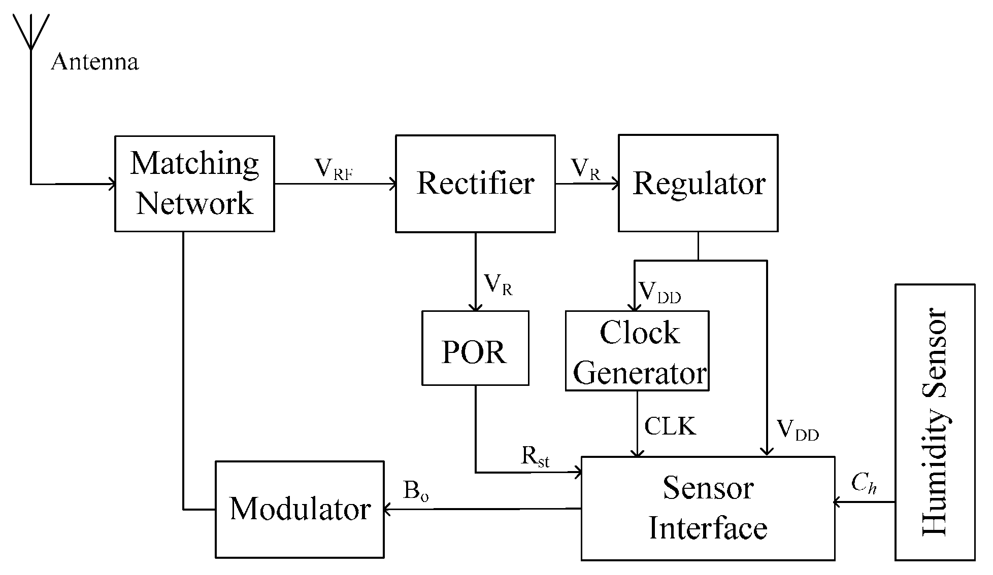
Because concrete is a high-loss material for electromagnetic wave transmission, this paper proposes a novel architecture to lower the overall power dissipation of wireless sensor for longer operating distance.
Figure 3 shows the architecture of the proposed wireless humidity sensor based on UHF RFID technology. The blocks, except for the antenna and matching network, are integrated on a single chip. The sensor antenna, which is matched with the sensor chip through the matching network, receives the electromagnetic waves from the RFID reader. The rectifier multiplies and transfers the received RF signal to a DC supply voltage
VR for the subsequent circuitry. Once the output of the rectifier reaches the operating voltage, the Power-On-Reset (POR) block generates a reset signal
Rst for the temperature sensor. The clock generator provides a reference clock CLK for the sensor interface. Because the sensor interface and the clock generator should operate under a stable supply voltage
VDD, a regulator block is employed to stabilize the output voltage of the rectifier. This architecture does not include the demodulator and the baseband blocks in the traditional RFID tag, which means that this wireless humidity sensor will operate without any addressing as long as the sensor receives enough energy from the RFID reader [
26].
3. Key Blocks Design
Inspired by the reported CMOS humidity sensor designs [
27,
28,
29,
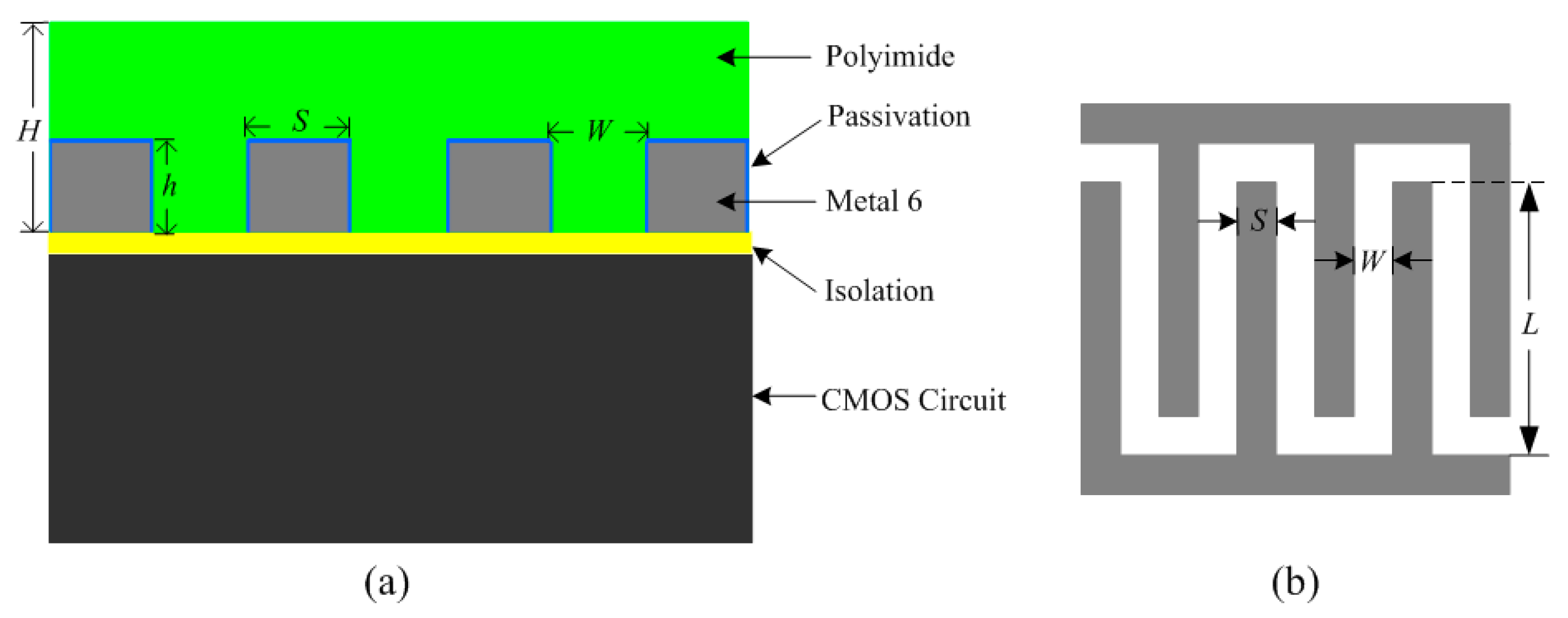
30], interdigitated top metal fingers with polyimide filled into the finger gaps, can be utilized for capacitive humidity sensing.
Figure 4a illustrates the structure of the proposed capacitive humidity sensor. The proposed humidity sensor was fabricated in the TSMC 0.18 μm 1P6M CMOS process. The top metal layer (Metal 6) was deposited and patterned with standard optical lithography and wet etching over the isolation layer to form the interdigitated structure. The sensing capacitor was then covered with a humidity-sensitive polyimide layer. The sensor is fabricated in a standard CMOS process without any post-processing. As seen from
Figure 4b,
L is the length of metal electrodes,
S is the width of each electrode, and
W is the distance between adjacent electrodes. The thickness of the polyimide layer is
H, which is generally larger than metal thickness
h. For a
N finger array sensor, the total sensor capacitance
Ch can be expressed as [
31]:
where
L is the length of metal electrodes,
h is the thickness of metal layer,
W is the distance between adjacent electrodes, and
εwet represents the dielectric constant of the polyimide film with absorbed water. Considering the factors including sensor capacitance, chip area sensitivity, etc., this work chooses
N = 40,
L = 200 µm,
W = 2.5 µm,
S = 2.5 µm,
h = 1 µm, and
H = 2 µm.
The capacitive humidity sensor acts as a capacitor when it works with the sensor interface. The traditional interface starts with a capacitance-to-voltage converter, which is then followed by a voltage-to-digital converter [
32,
33]. This technique can achieve high speed and high resolution performances. However, due to the use of an operational amplifier, this technique consumes too much power.
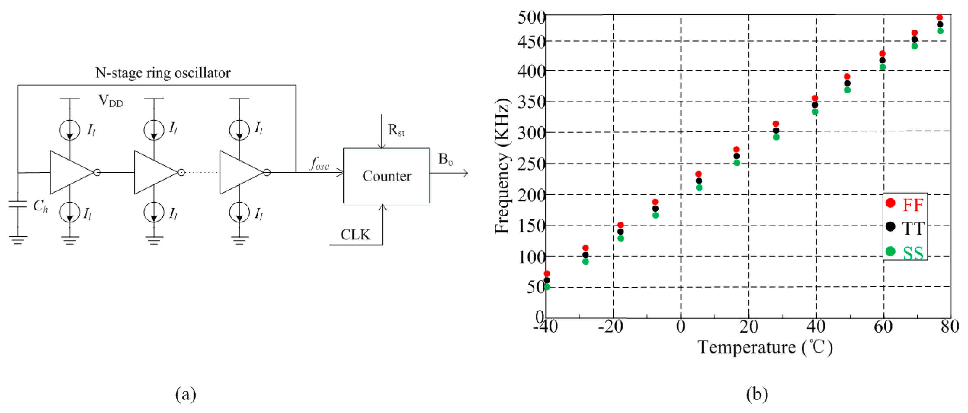
Figure 5a shows the architecture of proposed sensor interface, which converts the sensor signal in frequency domain for low-power application. The N-stage ring oscillator is employed to generate a controlled frequency
fosc which is then countered by a 10-bit counter to output the corresponding digital output
Bo. For a standard ring oscillator, assuming an equal rise and fall time for the different stages respectively, the oscillating frequency of the ring oscillator
fosc can be expressed as follows:
where
td is the delay time of the loop,
Il is the current flowing through the inverter,
Cl is the equivalent load capacitance of the loop, and
Vm is the swing range of the output voltage which mostly equals the supply voltage
VDD. Because
Cl is mainly determined by the capacitance
Ch of humidity sensor,
fosc is a sensor-controlled frequency and
Bo is the corresponding digital output of humidity sensor.
The simulation results of the proposed frequency
fosc versus temperature on different process corners are shown in
Figure 5b. The TT, FF, and SS corners correspond to “nominal”, “fast” and “slow” MOSFET devices, respectively. The
fosc achieves good linearity with temperature and the simulated worst case variation across corners is around ±9%.
A popular performance metric of a rectifier is its power conversion efficiency which is defined as:
where
Pout is the average DC output power generated at the output of the rectifier and
Pin is the average RF power available at the input of the rectifier. From a circuit-level point of view,
ηr is mainly degraded due to the forward drop of the switch diodes or transistors [
34]. Differed from the reported rectifier structure [
35,
36,
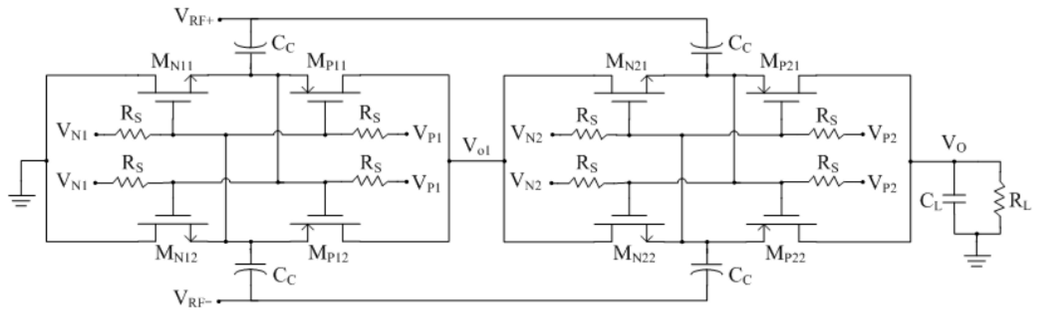
37],
Figure 6 shows the schematic of the proposed rectifier, which consists of two identical stages. The NMOS transistors M
N11–22 and PMOS transistors M
P11–22 form the differential-drive switch. In order to achieve a flat
ηr curve, the bias-voltage V
N1,2 and V
P1,2 are employed to boost the gate-source voltage of NMOS switch and PMOS switch, respectively [
31]. The large resistor
RS is added to block the AC component of V
N1,2 and V
P1,2. In CMOS process,
RS could be replaced by a PMOS transistor that operates in the cut-off region to avoid the large silicon area.
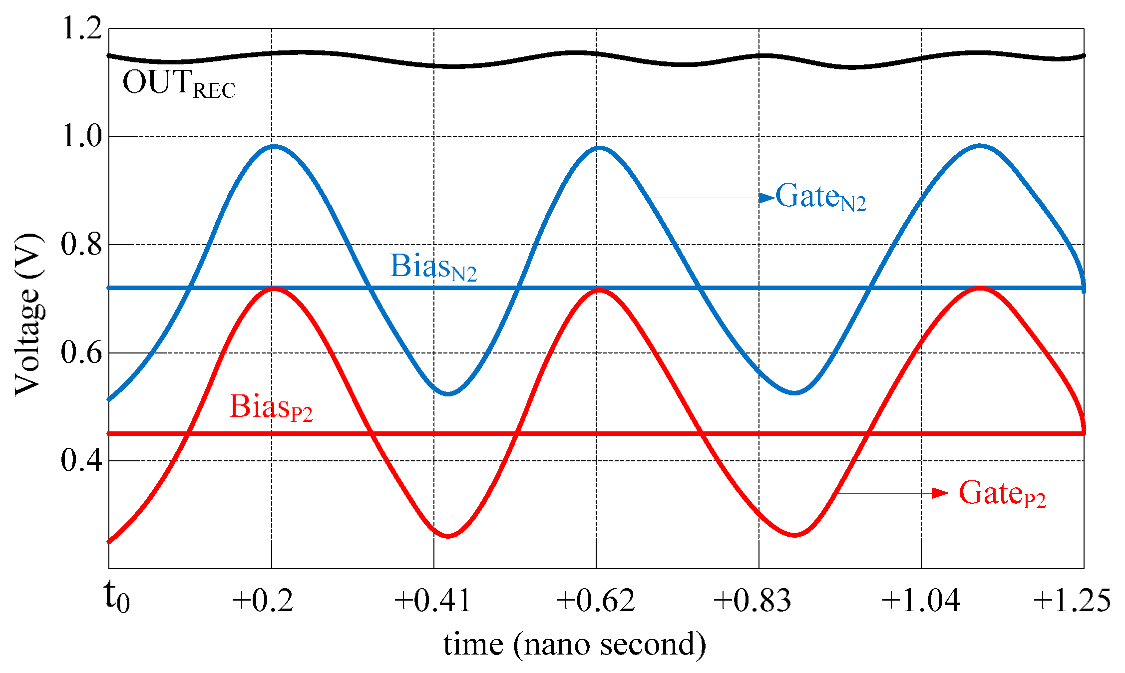
Figure 7 depicts in more details how the proposed scheme sets the DC level of PMOS and NMOS gate voltages. The RF intermediate voltage (M
U,
L) is superimposed on the bias voltages Bias
N2 and Bias
P2 to provide the shifted voltages Gate
N2 and Gate
P2 to the gate of NMOS and PMOS switches, respectively.
Due to the large variation of the output voltage of rectifier, a reference circuit with small supply voltage coefficient is necessary to generate a stable reference voltage. The traditional way to generate stable 1.25 V reference voltage is using a bandgap reference circuit [
38]. However, it cannot meet the low-voltage requirement of low-power application.
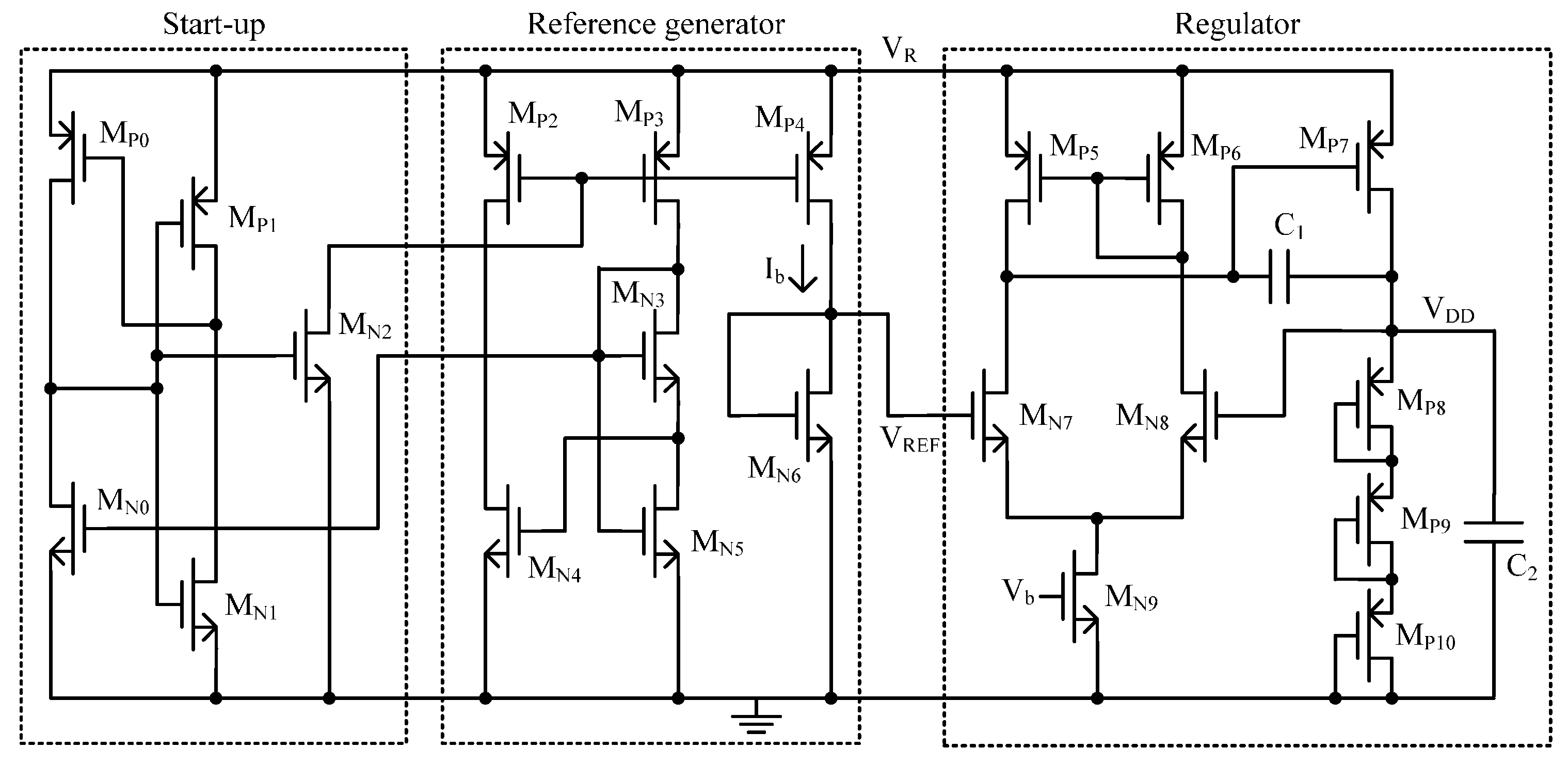
Figure 8 shows the schematic of the proposed voltage regulator. It is implemented in standard CMOS process without a bandgap reference and consists of three parts. The transisitors M
P0–M
P1 and M
N0–M
N2 compose a start-up block, which is added as a precautionary measure to ensure bias in the desired state. The transistors M
P2–M
P4 and M
N3–M
N6 compose a reference generator block to provide a reference voltage
VREF of 0.26 V which is compensated by temperature and supply voltage. The transistors M
P5–M
P10 and M
N7–M
N9 compose a regulator to generate a stable voltage
VDD of 1.0 V for other circuits.
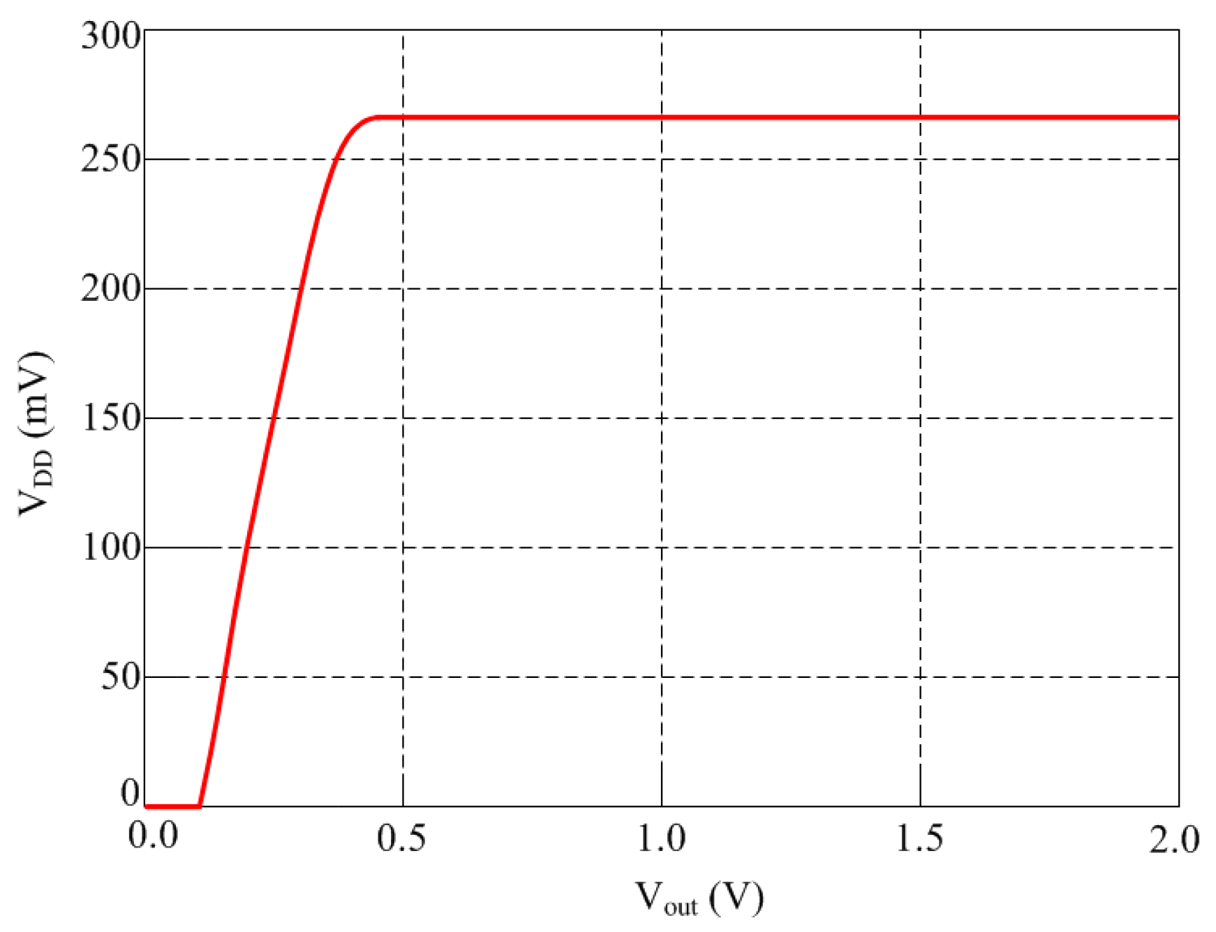
Figure 9 shows the
VDD −
Vout characteristic at room temperature of 25 °C. The circuit starts working properly with
VDD = 0.47 V. In the supply voltage range from 0.47 V to 2 V, an average reference voltage of 266.5 mV is generated. In this measured
VDD range, the output voltage changes at most by 1.8 mV, thus leading to a line sensitivity of 0.441%/V.
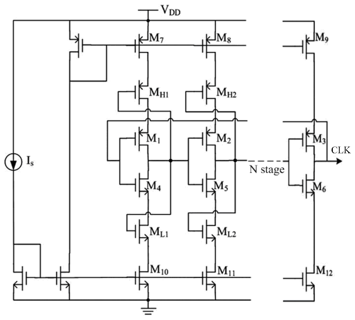
The clock generator always employs ring oscillator architecture based on current-starved inverters. The output voltage of traditional current-starved inverters is close to the supply voltage and ground, which improves the output range while increasing the power consumption. As is shown in
Figure 10, in order to achieve the balance between output range and power consumption, this paper proposed a novel structure of ring oscillator for the clock generator’s design. The PTAT oscillator discussed above in
Figure 3 also adopts the same architecture. The transistors M
1–M
6 consist of an
N stage current-starved inverter, the transistor M
7–M
9 and M
10–M
12 consist the current mirrors of inverter. Compared with the conventional structure, the extra transistors M
H1, M
H2, M
L1, and M
L2 are employed to reduce the voltage swing [
39].
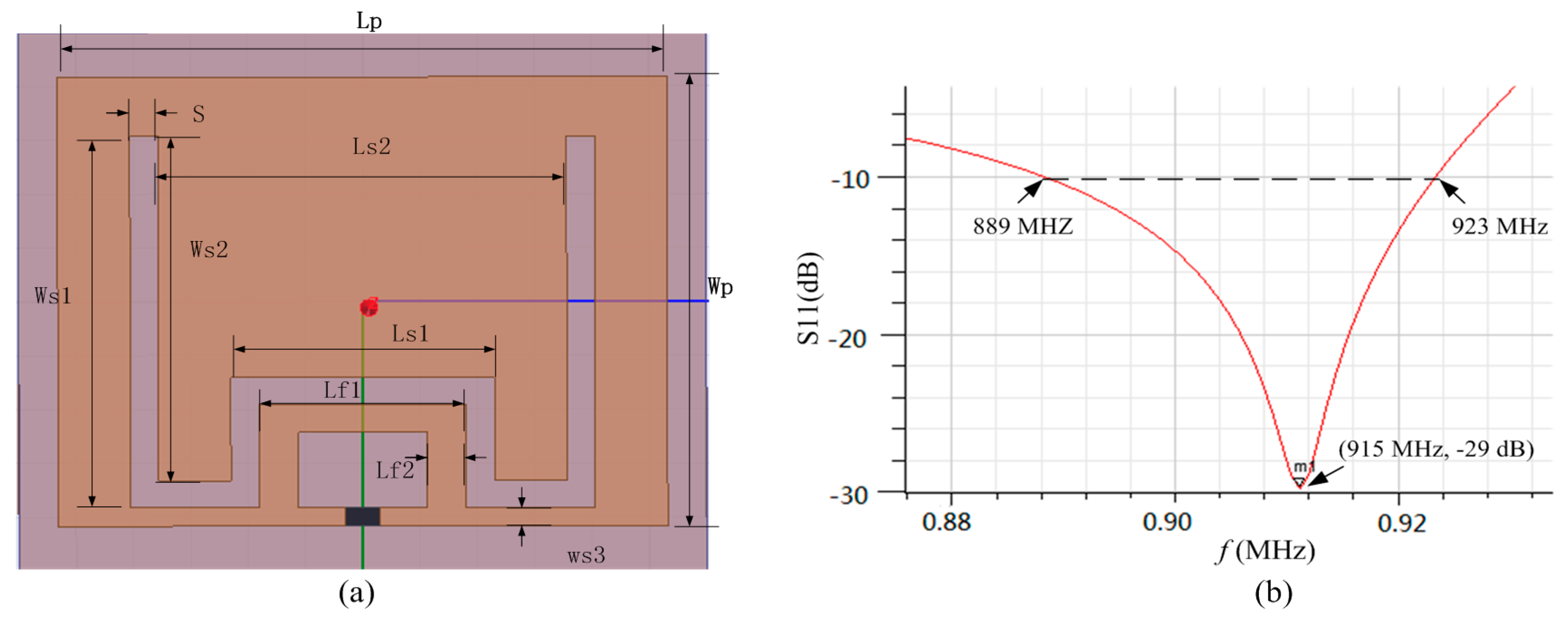
Microstrip antenna is designed by including a ground plane structure, which has a natural anti-metal advantage compared to the dipole antenna. The length of rectangular microstrip patch antenna length is approximately equal to half of its electrical length, which is not suitable for the miniaturization of tags. As shown in
Figure 11a, we presented a miniaturized microstrip antenna using the embedded short stub and U-type slot [
40]. The impedance of chip was 19-j172 Ω at 915 MHz. The copper traces with the thickness of 0.035 mm were printed on a FR4 substrate, whose permittivity is 4.4 and thickness is 2 mm. The current in the short circuited stub of this antenna is the strongest, so the impedance of the antenna can be adjusted easily by adjusting the value of Lf1 and Lf2. The short stub embedded in radiation patch internal can lead to the reduction of the antenna volume. Furthermore, because the current can flow around the slot, it results in the increasing of the length of current path and further achieving the miniaturization purpose. The return-loss plot of this antenna is shown in
Figure 11b. The return-loss at 915 MHz frequency is −29 dB and the bandwidth below −10 dB is from 889 MHz to 923 MHz. The gain of the proposed patch antenna is −3.2 dB and the maximum radiation direction is right above the antenna. The detailed parameters of the proposed patch antenna is shown in
Table 1.
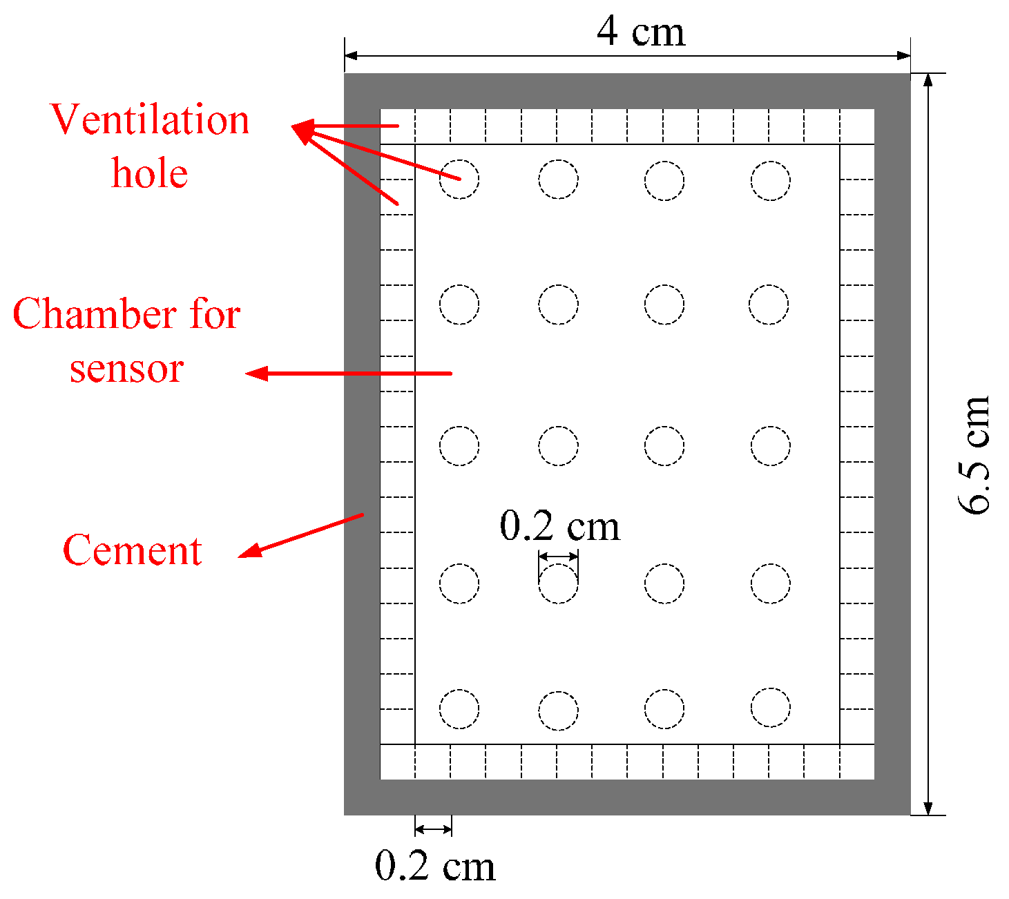
A protection device is necessary before the sensor tag is embedded into concrete, so that the sensor tag is not impaired by hydration heat arising from grouted concrete and not soaked directly in water of concrete. The transmission signal of sensor tag is sent out by electromagnetic wave, hence it is important to pay attention to wireless transmission impedance matching. Based on civil engineering techniques, this study proposes a protective high permeability acrylic package box. In order to keep the sensor in contact with the environment fully, 16 holes were punched on the side and 20 holes were punched at the bottom of the proposed package box.
Figure 12 shows the top view of protection device. The package box covers an area of 4 × 6.5 mm
2 and the diameter of the hole is 0.2 cm.
4. Experimental Characterization
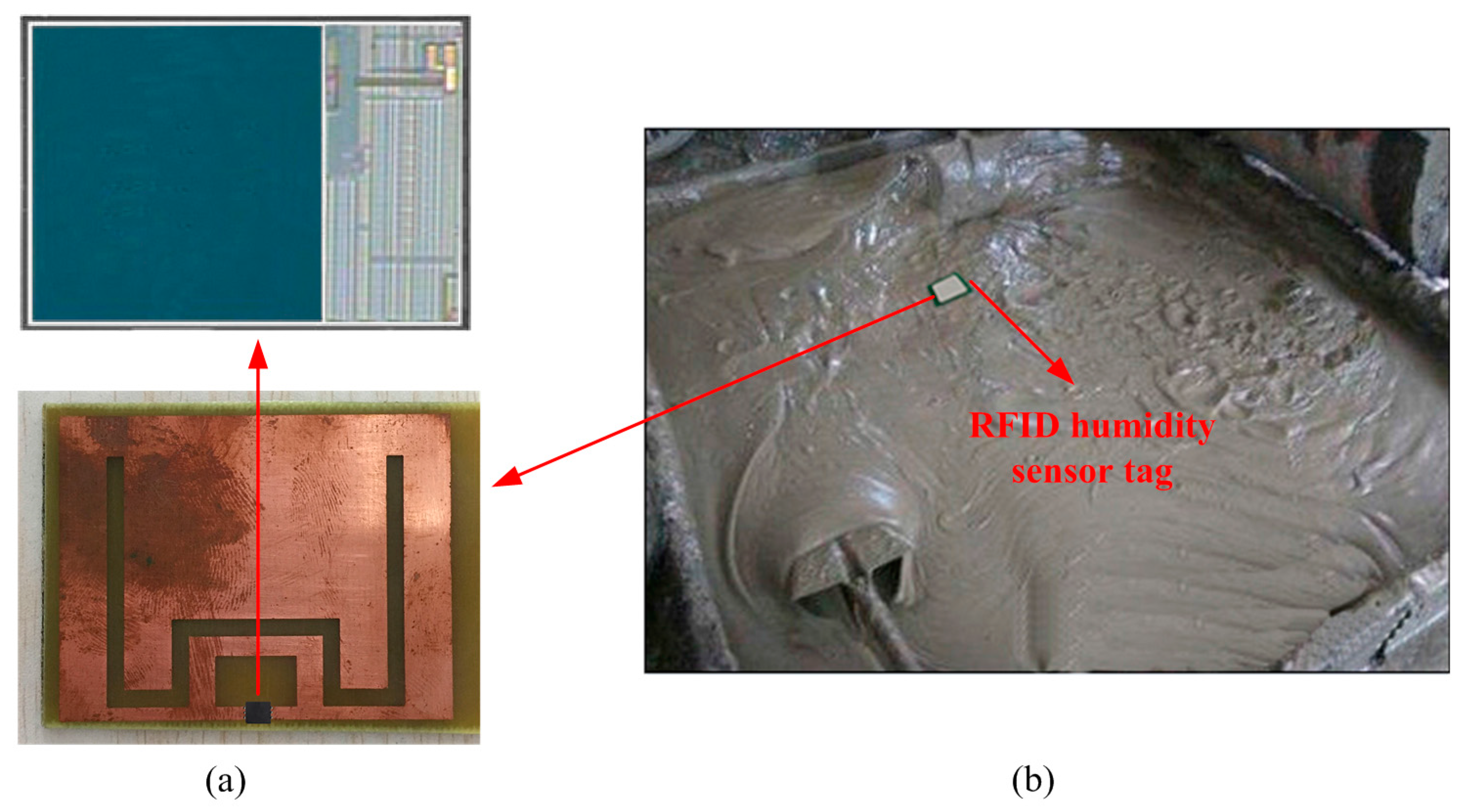
Figure 13a shows the proposed wireless humidity sensor, which was fabricated in the TSMC 0.18 μm CMOS process. The sensor tag chip covers around 8 × 3.5 mm
2 and was equipped with this antenna on FR4 substrate by using flip chip. Then the sensor tag was packaged with the package box for concrete monitoring as shown in
Figure 13b.
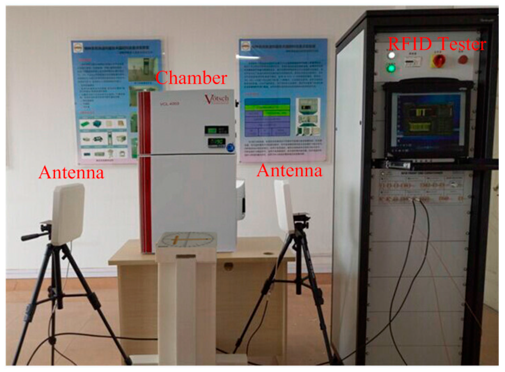
Figure 14 shows the wireless testing environment for the proposed humidity sensor. The VISN-R1200 is a special RFID tester from VI Service Network, which can process, analyze, and display the testing signals simultaneously. The sensor performance was measured in a temperature and humidity chamber of Votsch VCL4003. The temperature range and resolution of VCL4003 are −40–180 °C and 0.1 °C respectively, the humidity range and resolution of VCL4003 are 10%–98% RH and 1% RH, respectively.
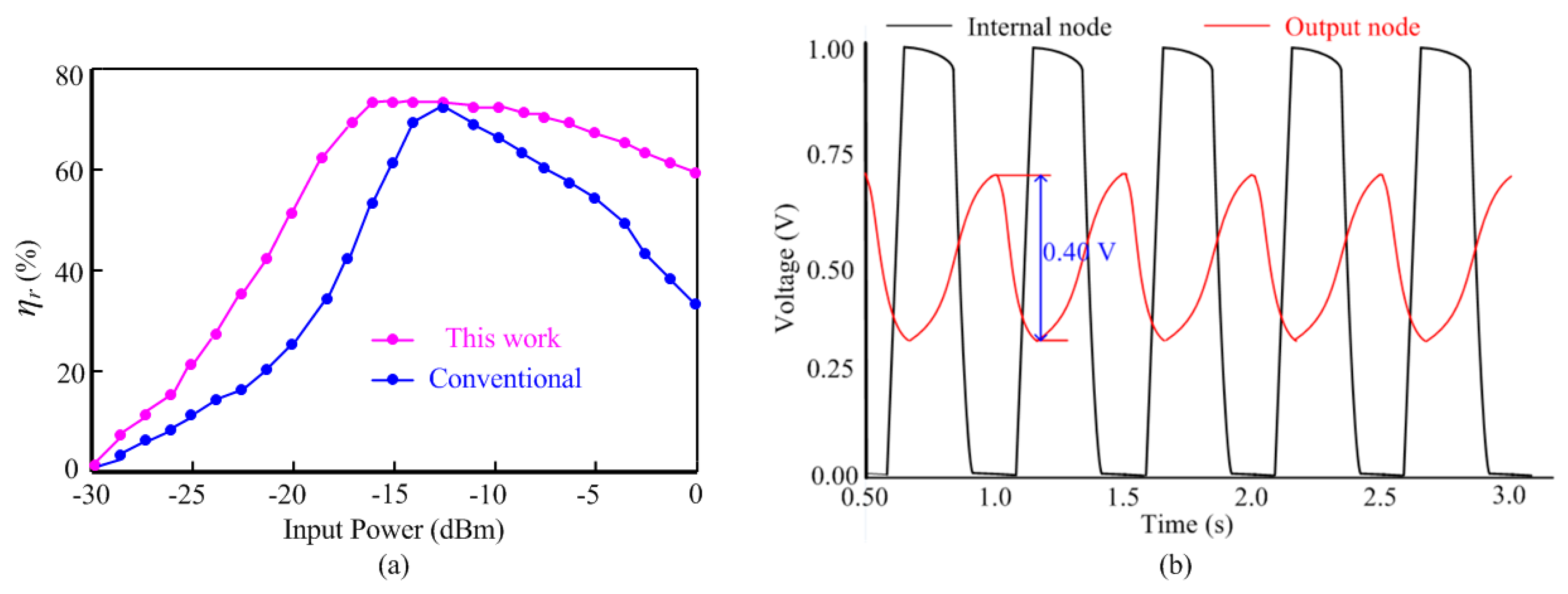
The measured
ηr curve of the proposed rectifier is shown in
Figure 15a. As compared to the conventional differential-drive rectifier [
36], the proposed rectifier shows a flat
ηr curve. When input power is 13 dBm, the two curves both reach the optimal point 69%. As for the input power range whose
ηr is above 60%, the proposed rectifier and the conventional rectifier achieve −19 dBm and −7 dBm range, respectively.
Figure 15b illustrates that the output node of the clock generator swings between the supply voltage 1.0 V and the ground, while the internal nodes of the clock generator vary from 0.3 V to 0.7 V. The reduction of the voltage swing to nearly 50% of its nominal value lowers the dynamic power consumption of the internal nodes by 75% and the overall power consumption by much more than 25%.
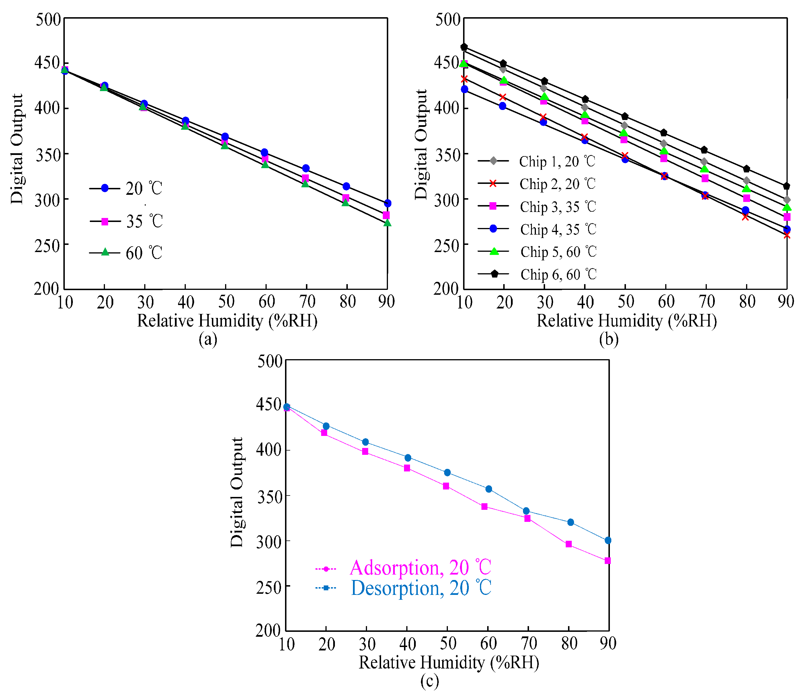
Figure 16a shows the twice measured results of the sensor tag at 20 °C, 35 °C, and 60 °C respectively within the relative humidity (RH) range from 10% to 90%. The sensor tag achieves high linearity and shows a maximum error of 12% for 40 °C offset. The temperature dependence of the dielectric constant of the polyimide film
εwet results in this error.
Figure 16b shows the measured results of six test chips at 20 °C, 35 °C, and 60 °C within the range from 10% RH to 90% RH. Due to the process variation, the chips exhibit different digital outputs for a given RH value but all the results show an excellent linearity. The average sensitivity is 0.55% RH. The hysteresis performance of the sensor at 20 °C is shown in
Figure 16c. The maximum difference between the moisture adsorption and desorption at the point 80% RH does not exceed 10%.
Table 2 compares the performances of the proposed RFID humidity sensor with previous RFID humidity sensor. The chipless RFID humidity sensor [
18] is specially designed for ultra-low cost application, however it has the lowest accuracy because there is no digital block in it. The wireless humidity sensor with 13.56 MHz operating frequency [
19] can obtain a high power conversion efficiency, however its operating distance is very limited. A RFID-based temperature and humidity sensor [
20] can achieve complex function, however its operating distance is only 2.7 m. The proposed wireless humidity sensor achieves a minimum power dissipation of 5.7 μW, resulting in a maximum operating distance of 17 m in free space. Our design is especially for the tough sensing application in concrete.
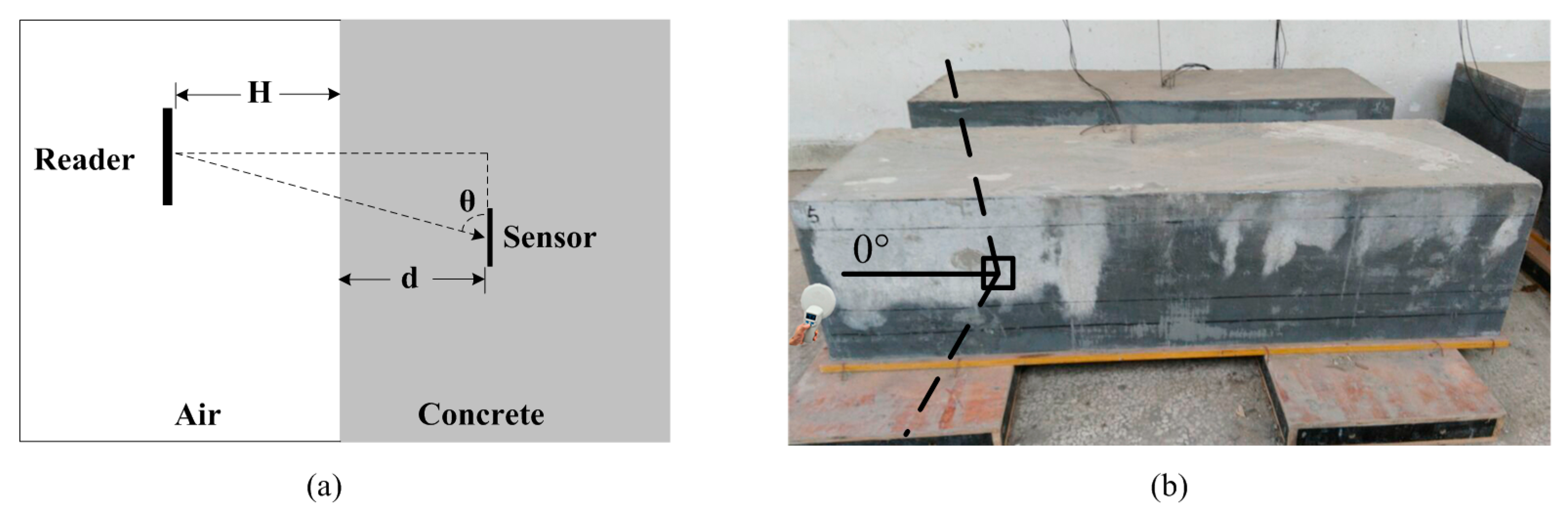
Figure 17a shows the experimental scheme of the proposed wireless sensor in concrete. The depth of the wireless humidity embedded in concrete is
d, the distance of the RFID reader placed above the concrete is
H, the incidence angle between the reader and the sensor is
θ. The photo of the test site is shown in
Figure 17b.
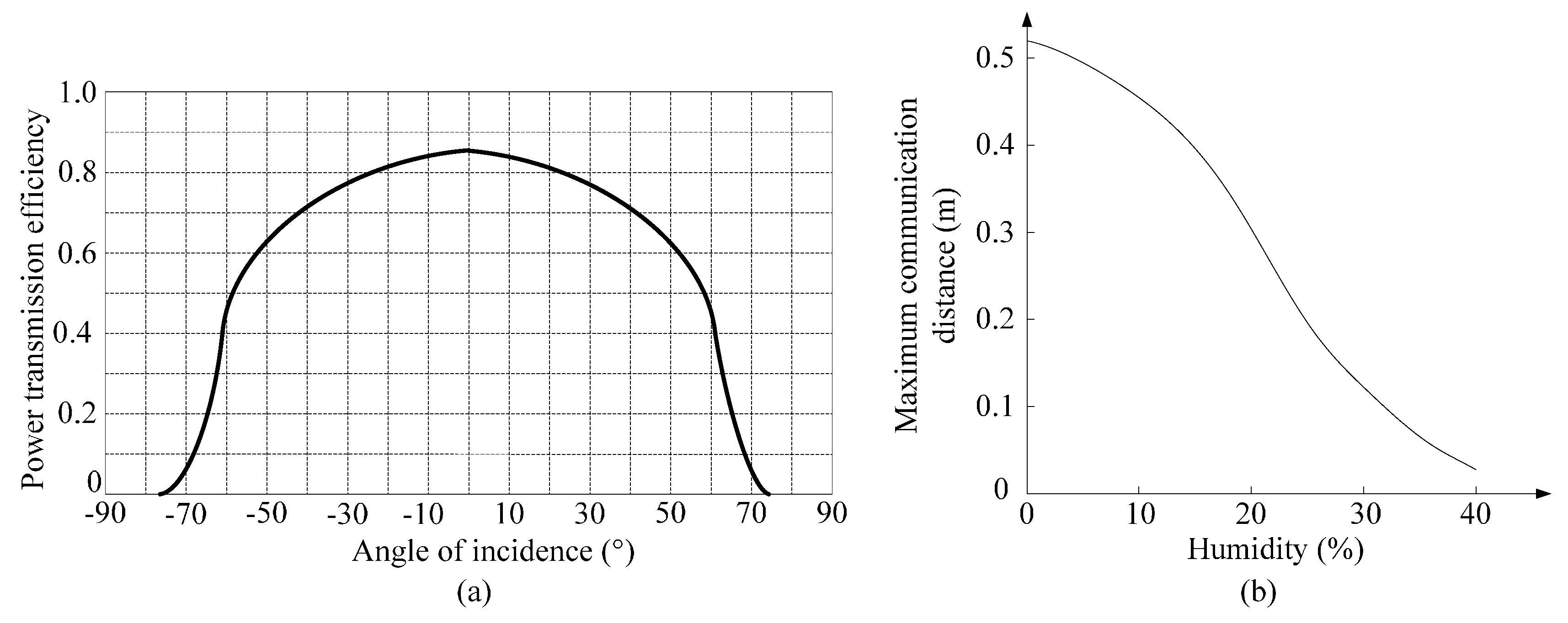
We embedded the sensor into the concrete at a depth of 8 cm and then investigated the influence of incidence angle on power transmission. The relationship between the incidence angle
θ and power transmission is shown in
Figure 18a. From that, we can see the minimum power loss is achieved when
θ is 90°, the power transmission efficiency is 85%. When
θ is larger than 75°, the power transmission efficiency is nearly 0%. Hence, in order to achieve the best test results, the incidence angle should be as vertical as possible. When we set
θ = 90° and
d = 8 cm, we measure the maximum communication distance of RFID reader. A calibrated humidity sensor SHT75 is embedded together with the proposed wireless humidity sensor to monitor the concrete humidity. For each measurement, the reader was instructed to perform 1000 attempts to read the sensor data from the wireless humidity sensor. When the success ratio remains above 80%, the communication distance is considered to be reliable. As shown in
Figure 18b, the measured maximum communication distance decreases when the concrete humidity increases. The maximum communication distance is 0.52 m or 0.11 m respectively when the concrete humidity is 0% or 30%.
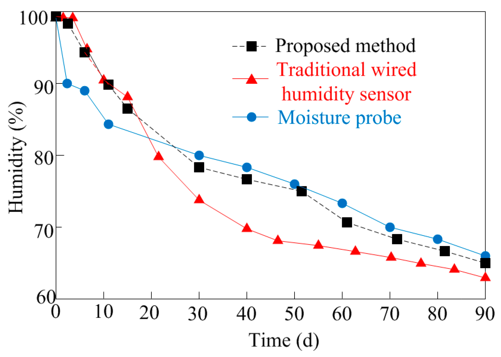
This work employs concrete made of normal aggregate (1 h pre-wetting, moisture content of 6.6%) as the sample. The proposed wireless humidity sensor is embedded at a depth of 8 cm inside the concrete sample with the calibrated wired humidity sensor SHT75. The results measured by these two sensors compared with results of the moisture probe are plotted in
Figure 19. According to [
41], during the early age of concrete maturing, the traditional wired humidity sensor can get more accurate results in the first 14 days resulting from the exchange of air when measuring by moisture probe. Due to the long time embedded in wet concrete, zero drift of the traditional wired humidity sensor will decrease the accuracy of the measurement results. Thus, after the 14th day the moisture probe achieves higher measurement accuracy. From
Figure 18 we can see in the first 14 days the proposed wireless sensor achieves nearly the same results with the traditional humidity sensor. After that, the measurement results of the proposed sensor are close to the results measured by the moisture probe. Hence the proposed wireless humidity sensor achieves better performances during the entire measurement.


