Article

The Tetrel Bond and Tetrel Halide Perovskite Semiconductors

by
Pradeep R. Varadwaj
1,2,*,
Arpita Varadwaj
1,*,
Helder M. Marques
2 and
Koichi Yamashita
1
1
Department of Chemical System Engineering, School of Engineering, The University of Tokyo, 7-3-1, Tokyo 113-8656, Japan
2
Molecular Sciences Institute, School of Chemistry, University of the Witwatersrand, Johannesburg 2050, South Africa
*
Authors to whom correspondence should be addressed.
Int. J. Mol. Sci. 2023, 24(7), 6659; https://doi.org/10.3390/ijms24076659
Submission received: 26 February 2023 / Revised: 21 March 2023 / Accepted: 23 March 2023 / Published: 3 April 2023
(This article belongs to the Topic Theoretical, Quantum and Computational Chemistry)

Abstract

:
The ion pairs [Cs+•TtX3] (Tt = Pb, Sn, Ge; X = I, Br, Cl) are the building blocks of all-inorganic cesium tetrel halide perovskites in 3D, CsTtX3, that are widely regarded as blockbuster materials for optoelectronic applications such as in solar cells. The 3D structures consist of an anionic inorganic tetrel halide framework stabilized by the cesium cations (Cs+). We use computational methods to show that the geometrical connectivity between the inorganic monoanions, [TtX3], that leads to the formation of the TtX64− octahedra and the 3D inorganic perovskite architecture is the result of the joint effect of polarization and coulombic forces driven by alkali and tetrel bonds. Depending on the nature and temperature phase of these perovskite systems, the Tt···X tetrel bonds are either indistinguishable or somehow distinguishable from Tt–X coordinate bonds. The calculation of the potential on the electrostatic surface of the Tt atom in molecular [Cs+•TtX3] provides physical insight into why the negative anions [TtX3] attract each other when in close proximity, leading to the formation of the CsTtX3 tetrel halide perovskites in the solid state. The inter-molecular (and inter-ionic) geometries, binding energies, and charge density-based topological properties of sixteen [Cs+•TtX3] ion pairs, as well as some selected oligomers [Cs+•PbI3]n (n = 2, 3, 4), are discussed.

Graphical Abstract

1. Introduction

All-inorganic [1,2,3] and organic–inorganic [4,5,6,7] metal halide perovskites are a special class of semiconducting materials used in photovoltaics [8], photodetectors [9], and photocatalysis [10,11]. The continuing development of a variety of these materials has been well documented [12,13,14]. The hybrid organic–inorganic metal halide perovskites have appeared in a variety of dimensions, nD (n = 0–3) [15,16,17,18], as have the all-inorganic tetrel halide perovskites [19,20,21].
The well-known 3D organic–inorganic metal halide perovskites have the generic formula ATtX3 (A = MA+, methylammonium [CH3NH3+]; FA+, formamidinium [HC(NH2)2+]; Tt = Pb, Sn, Ge; X = Cl, Br, I). The all-inorganic counterparts are obtained when the A-site cation is replaced by an inorganic moiety, such as Cs+, Rb+, or K+, for example. The first type has been somewhat misleadingly referred to as organo-metal halide perovskites [8,9,17,22]; they are now referred to as single metal halide perovskites [23,24], with generic formula ABX3, where A is a monovalent cation, B is a divalent metal cation, and X is a monovalent halide anion [25]. ATtX3 comprises an anion (TtX3) and a cation A+, with Tt formally in its +2-oxidation state.
Three-dimensional metal halide perovskites form cage-like structures [15,16], while 2D [26], 1D [17], and 0D [17,27] perovskites form layered-, chain-, and quantum dot-like structures, respectively. At first, positively charged inorganic or organic moieties (e.g., Cs+ or MA+) are incorporated inside a negatively charged inorganic architecture. The inorganic skeleton (i.e., [TtX3]) of the crystal in 3D is formed from a negatively charged repeating unit ([TtX3]) and these are linked to each other in an infinite array in the presence of the inorganic or organic cations. Why these negatively charged units are repeated in an infinite crystal appears not to have been discussed in the perovskite literature, nor have their bond-specific roles. A number of studies have shown that the extrema of the valence and conduction bands in these 3D materials are driven by orbital contributions arising from the inorganic framework formed by the M and X atoms, and the A-site cation is not involved in contributing to or elevating the functionality of these materials [28,29]. However, other studies have demonstrated that the organic cation plays an important role in determining the hole density of some low-dimensional metal halide perovskites [30]. Indeed, there has been some controversy concerning the actual role played by the A-site cation [31,32,33,34,35].
The aim of this study is to shed light on one of the pressing issues mentioned above. In particular, we shall demonstrate that when a TtX3 (X = Cl, Br, I) anion is placed near the electrostatic field of an inorganic cation, such as Cs+, they not only like each other by a coulombic attraction, but the electric field of the positively charged moiety Cs+ is able to polarize the charge density on the electrostatic surface of TtX3. This results in the formation of electron density-deficient (positive) sites on the electrostatic surface of TtX3 in [Cs+•TtX3] (Tt = Pb, Sn, Ge; X = I, Br, Cl, F) ion pairs, except when Tt = Si; these are the building blocks of the 3D structure of CsTtX3. The strength of these positive sites on Tt is sufficient to attract nucleophiles on the surfaces of the halogen derivative on another similar interacting unit of TtX3, and a repetition of this process results in the formation of an infinite inorganic framework in the presence of Cs+ ions. We show that the attractive interaction between a pair of TtX3 units in a pair of ion pairs is nothing other than a “tetrel bond” [36]. The physical chemistry of the tetrel bond, and other non-covalent interactions (e.g., the alkali bond [37]), in a variety of [Cs+•TtX3] ion pairs and in the [Cs+•PbI3]n (n = 2, 3, 4) oligomers is discussed.
A tetrel bond occurs in chemical systems when there is evidence of a net attractive interaction between an electrophilic region associated with a covalently or coordinately bonded tetrel atom (or atoms) in a molecular entity and a nucleophilic region in another, or the same, molecular entity [36]. In other words, the tetrel bond occurs when an electrophilic σ-hole on the surface of the Tt atom in a molecular entity R–Tt is in coulombic engagement with the nucleophile on the same or another molecular entity. An electrophilic σ-hole is an electron density-deficient region of positive electrostatic potential that appears on the electrostatic surface of an atom A opposite to the R–A covalent bond and has the ability to sustain an attractive bonding engagement with the negative site [38,39,40,41].
This study employs Density Functional Theory (DFT) and focuses primarily on the ion-pair systems of [Cs+•PbI3]n (n = 1, 2, 3, 4), but Quantum Theory of Atoms in Molecules (QTAIM) and Molecular Electrostatic Surface Potential (MESP) calculations are also performed on [Cs+•TtX3] (Tt = Si, Ge, Sn X = F, Cl, Br) ion pairs that are supposedly the building blocks in 3D tetrel halide perovskites. The study shows that the formation of the inorganic framework and the geometric stability of cesium tetrel halide perovskite systems arise from the same underlying interactions, tetrel and alkali bonds. Crystalline cesium tetrel halide perovskites were found by searching the Inorganic Crystal Structure Database (ICSD) [42,43] and can also be found on the Materials Project Database [44].

2. Results

2.1. Illustrative Crystal Geometry of Cesium Tetrel Halide Perovskites

The crystal structures of CsGeX3 (X = Cl, Br, I) have been known for some time [45]. The crystal structure of the high-temperature Pm 3 m phase of CsPbI3 was reported in 2008 [46], while the low-temperature orthorhombic structures Pmnb (ICSD ref: 27979), Pbnm (ICSD: 434338; 21955) [47], Pnam (ICSD ref: 264725) [48], and Pnma (ICSD ref: 32301–32314; 161480; 29350; 27484; 20759; 17016) [
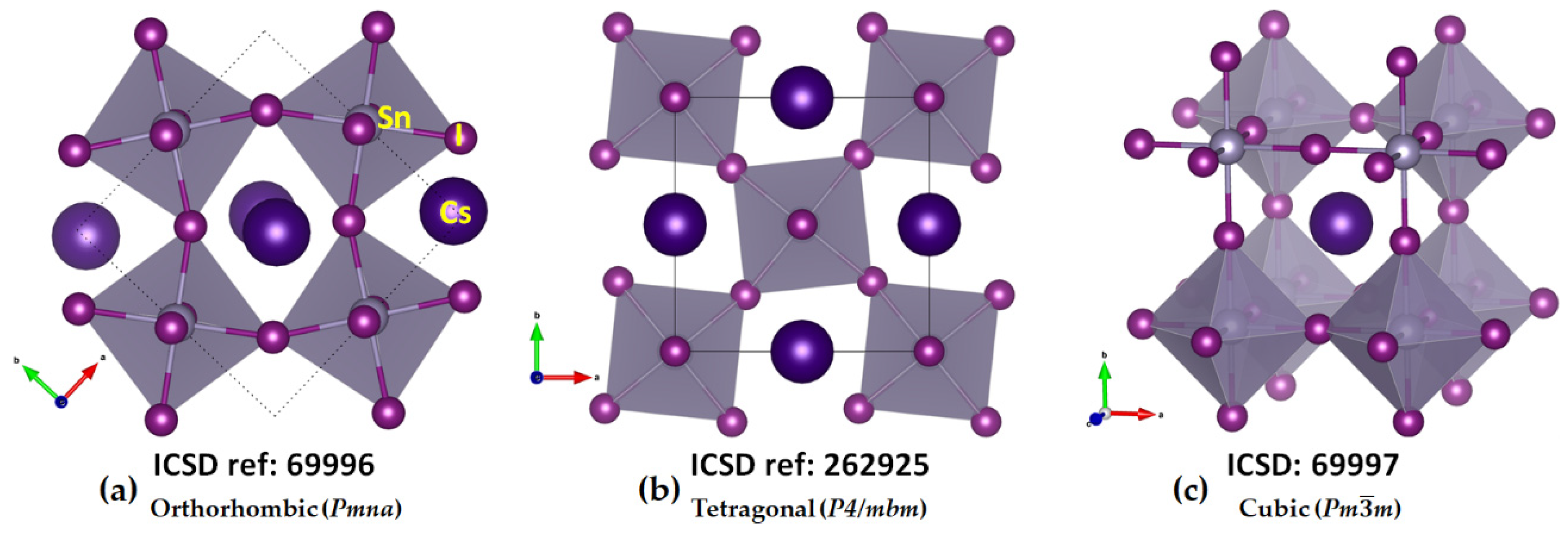
49] of the same system have been known since 1959. Regardless of the nature of the temperature phase, the TtX64− framework is common, featuring corner-sharing octahedra. These are tilted in the low-temperature phases along the crystallographic axes but linearly arranged in the high-temperature cubic phase [6,50,51]. These features are evident in the orthorhombic, tetragonal, and cubic phases of CsSnI3 (see Figure 1a–c, respectively). They are also reminiscent of cesium lead halide perovskites, CsPbI3. The high-to-low temperature phases of CsPbI3 [52] are called the α (645K), β (510K), and γ (325K) phases, with space groups Pm 3 m, P4/mbm, and Pbnm, respectively. A common feature of these systems is that the TtX3 anions are linked to each other through tetrel bonds, a feature revealed in this study, and these bonds are responsible for the formation of the 3D inorganic frameworks. All these perovskite systems mentioned above are semiconductors, and several of them have found application in photovoltaics. However, the black orthorhombic form of CsSnI3 features p-type metallic behavior with low carrier density, despite an optical band gap of 1.3 eV [53].
(a) 
Cesium Tetrel Iodide Perovskites
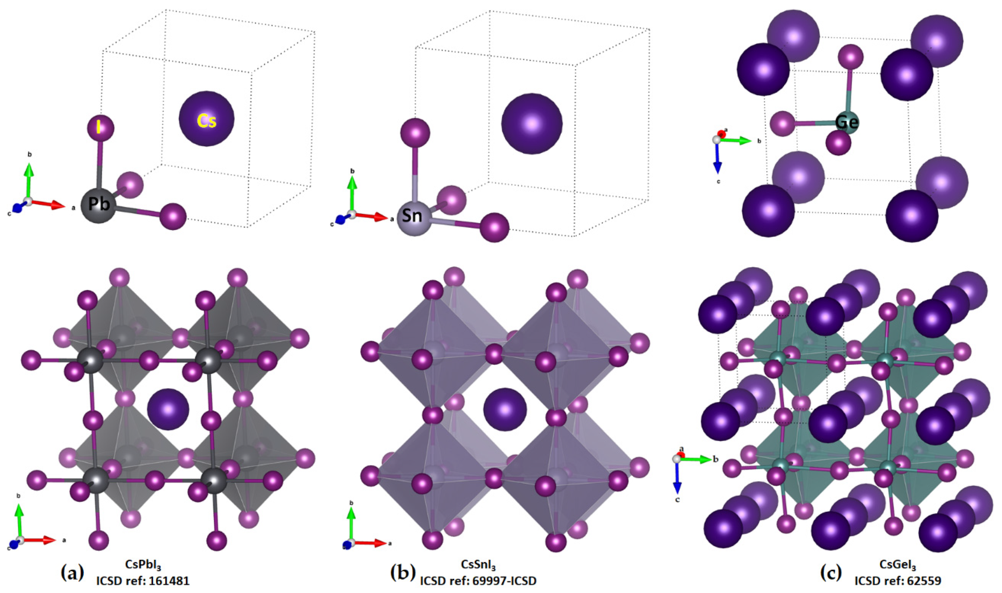
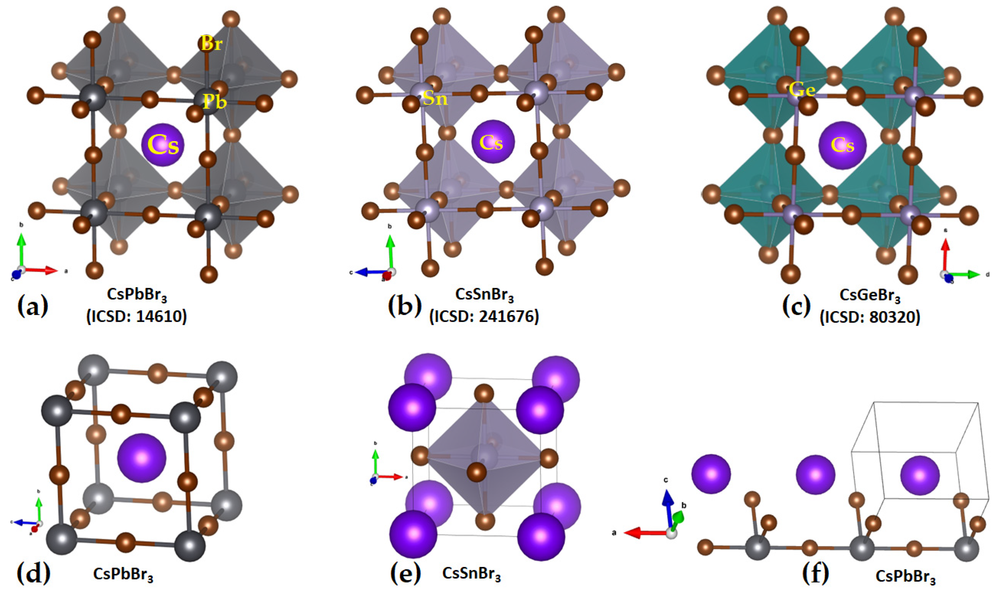
The unit-cell (top) and cage-like (bottom) structures of cesium tetrel iodide perovskites, CsTtI3 (Tt = Pb, Sn and Ge), are shown in Figure 2a–c. The unit cell, an ion pair, [Cs+•TtI3], when periodically expanded, reveals a cage-like structure. The formation of the latter is driven by Tt···I tetrel bonds, which are equivalent and linear when Tt = Pb and Sn and quasi-linear and non-equivalent when Tt = Ge. For instance, the distances associated with the Tt–I coordinate bonds within the [TtI3] fragment and Tt···I tetrel bonds between a [TtI3] pair are 3.145 and 3.110 Å in cubic (Pm- 3 m) CsPbI3 (Figure 2a) and CsSnI3 (
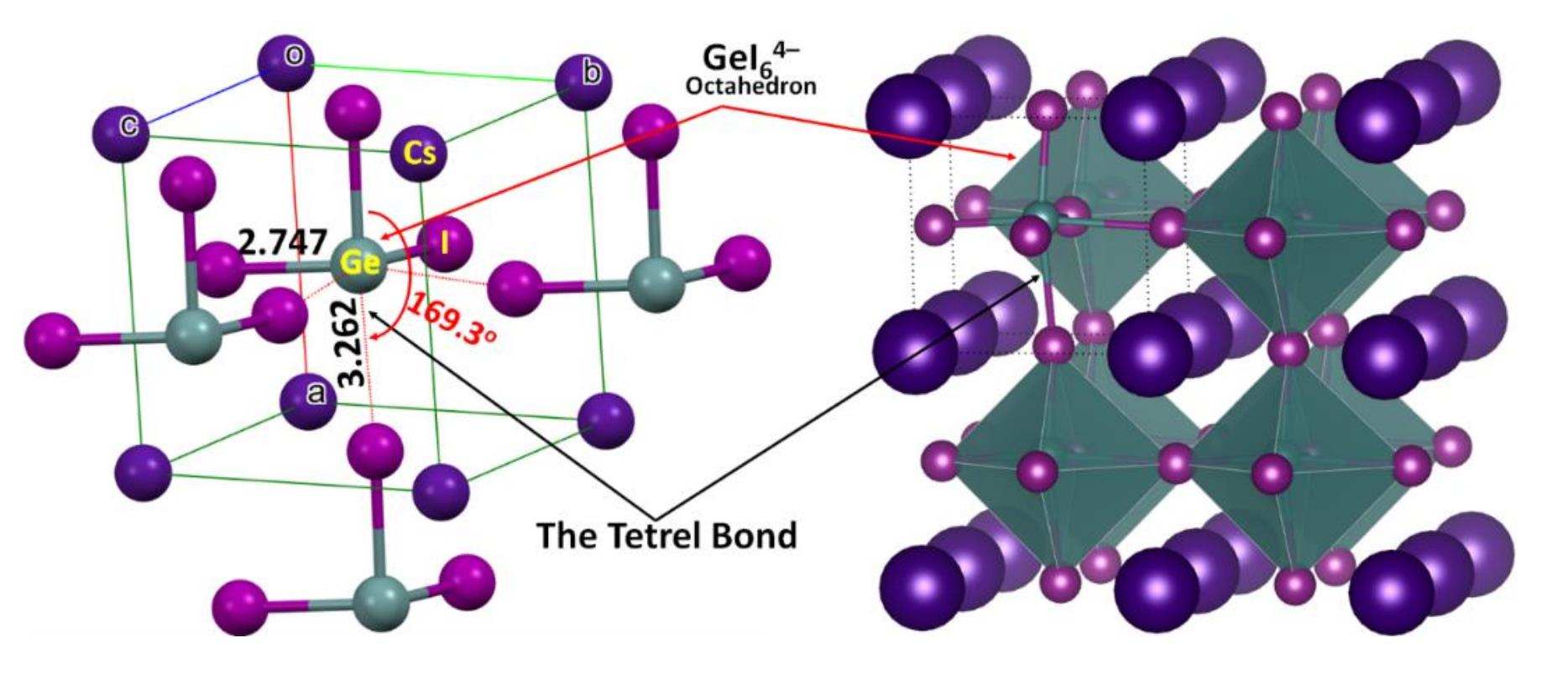
Figure 2b), respectively. Because of the small size of the Ge cation, CsGeI3 perovskite is not cubic (Figure 2c) and crystalizes in the rhombohedral space group R3m. Each of the three equivalent Ge–I coordinate bonds within the [GeI3] fragment is 2.747 Å, and each of the three equivalent Ge···I tetrel bonds between four [GeI3] fragments linked with each other in the CsGeI3 is 3.262 Å. The latter are directional but quasi-linear, ∠I–Ge···I = 169.3°, which is equivalent to the tilting angle, ∠Ge···I–Ge = 169.3°, of the octahedra along each of the three principal axes. There is no structure of CsSiI3 deposited in the ICSD.
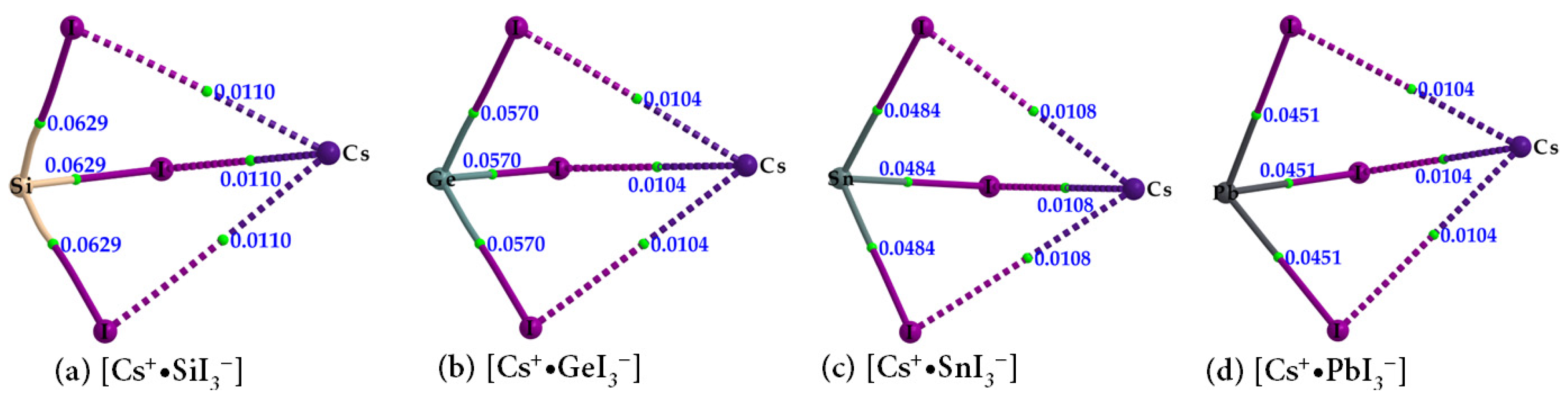
In order to shed some light on the why the entirely negative anions [TtI3] attract each other, thus forming tetrel bonds between them (Figure 2, bottom), we performed both QTAIM and MESP analyses. The molecular graphs of cesium tetrel iodide perovskite ion pairs, [Cs+•TtI3] (Tt = Si, Ge, Sn and Pb), are shown in Figure 3a–d. The topology of the bond paths suggests that Tt–I coordinate bonds, characterized by solid lines, are shorter and stronger than the Cs···I close contacts, described by dotted lines; this is in line with the charge density values at their corresponding bcps, meaning that the Cs···I close contacts are weaker than the Tt–I coordinate bonds. Focusing on CsPbI3 as a representative example of this series, each PbI3 unit, which is a face of the PbI64− octahedron, is involved in an attractive coulombic interaction with Cs+, thereby forming the ion pair [Cs+•PbI3]. As shown in Figure 2a (bottom), a single cation simultaneously interacts with eight PbI3 faces of eight PbI64− octahedra, forming a cage-like structure, with Cs+ trapped inside the cage formed by the eight PbI64− octahedra. In other words, the arrangement between the anion and the cation in CsPbI3 is such that each face of the corner-shared PbI64− octahedra hosts a Cs+ cation (cf. Figure 2a).
The question that immediately arises as to why the cesium tetrel halide perovskites with Tt = Pb, Sn, and Ge have been synthesized, but not with Tt = Si. This is answered below. In short, it is the result of the nucleophilic nature of the electrostatic potential on the surface of Si in molecular [Cs+•SiI3] that prevents self-assembly of these recurring units.
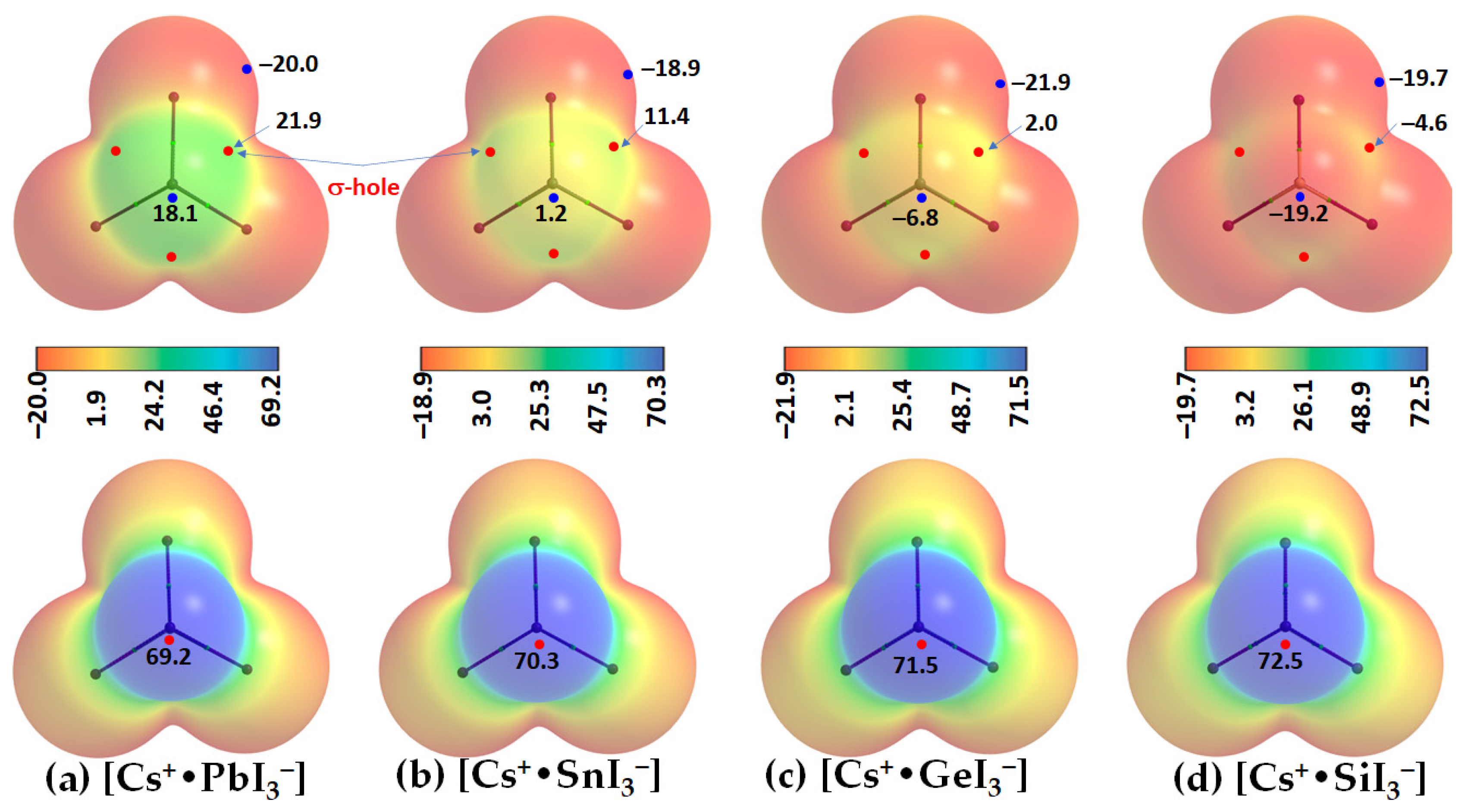
Two distinct features can be readily seen from Figure 4. First, the tetrel atom in the ion pairs carries either a negative or a positive potential (VS,max < 0 or VS,max > 0) along the outermost extension of each I–Tt bond. In specific, VS,max > 0 in [Cs+•PbI3], [Cs+•SnI3], and [Cs+•GeI3], becomes progressively less positive, and switches to VS,max < 0 in [Cs+•SiI3]. This is the result of the polarizing field induced by Cs+ when it is placed close to the [TtI3] anion. The polarization of the surface charge density of Tt in [TtI3] is accompanied by an appreciable transfer of charge from the iodide to Cs+ cation, varying between 0.085 and 0.116 e. This causes the charge density on the surface of Tt to be rearranged in such a manner as to produce depleted regions of charge density on its surface. The charge density-depleted regions appear along the outermost extensions of the I–Tt bonds when Tt = Pb, Sn, or Ge, but not when Tt = Si. These charge density regions on the tetrel atoms along the extension of the three I–Tt bonds are characteristic of σ-holes since they appear opposite to the I–Tt σ coordinate bonds; thus, σ-holes on Tt are electrophilic in [Cs+•PbI3], [Cs+•SnI3], and [Cs+•GeI3] (VS,max > 0; see Figure 4a–c) but nucleophilic in [Cs+•SnI3] (VS,max < 0; Figure 4d).
Secondly, a local most minimum of potential, VS,min, is found on the Tt atom in each [Cs+•TtI3], appearing on its surface along the outer extension of the C3v axis. It is positive in [Cs+•PbI3] and [Cs+•SnI3] and negative in [Cs+•GeI3] and [Cs+•SnI3]. The strength of the minimum of potential decreases in the order Pb (VS,min = 18.1 kcal mol−1) < Sn (1.2 kcal mol−1) < Ge (–6.8 kcal mol−1) < Si (–19.2 kcal mol−1). This indicates that Pb and Sn are entirely electrophilic, unlike Ge and Si. The MESP graphs also suggest that the stereochemically active lone pair of the Tt sites are squeezed onto the surfaces of the iodides when Tt = Pb and Sn, but not when Tt = Ge and Si. This conclusion is in accordance with a previous study where it was suggested that “a stereochemically active lone pair of electrons of the Pb atom may lie between the two I atoms in the plane” [55]. It was recently argued that the s2 lone pair on heavy main-group elements in their lower oxidation states is responsible for the emergence of polar ground states in some ferroic materials and causes a crystallographically hidden, locally distorted state that appears upon warming, a phenomenon referred to as emphanisis [56]. Others have argued that PbO and PbS in both the rocksalt and litharge structures, which have distorted Pb2+ octahedra, are not the result of chemically inert, stereochemically active lone pairs, but instead are the result of asymmetric electron densities that rely on direct electronic interaction with the coordinated anions [57]. Further discussion on the importance of stereochemically active lone pairs on Pb in Pb(II) halide compounds can be found elsewhere [58].
The local most maximum potential on the surface of Cs+ in the ion pairs is positive, VS,max > 0, and Cs+ becomes increasingly more electrophilic down the series [Cs+•PbI3], [Cs+•SnI3], [Cs+•GeI3], and [Cs+•SiI3]. This is expected, as Si is relatively more electronegative in the tetrel series, hence, the ability of Cs+ to polarize electron density of small-sized Tt decreases. In all cases, both the lateral and axial portions of the halide atoms in [TtI3] are entirely negative, with VS,min < 0, as seen in Figure 4a–d.
Our QTAM results in Figure 3 and Table 1 suggest that the Si–I bonds have appreciable covalency, whereas the Tt–I (Tt = Ge, Sn, and Pb) in [Cs+•TtI3] have a more ionic character. The Si–I bonds are characterized by negative values of both ∇2ρb and Hb at the Si–I bcps. Although the Tt–I (Tt = Ge, Sn, and Pb) bonds possess ionic character, the negative Hb values at the Tt–I bcps are indicative of some measure of covalency. These coordinate bonds clearly have mixed bonding character. On the other hand, the cesium-centered charge-assisted alkali bonds, Cs···I, possess closed-shell character (∇2ρb > 0 and Hb > 0) and the charge density at the Cs···I bcps is significantly smaller than that at the Tt–I bcps.
(b) 
Cesium Tetrel Bromide Perovskites
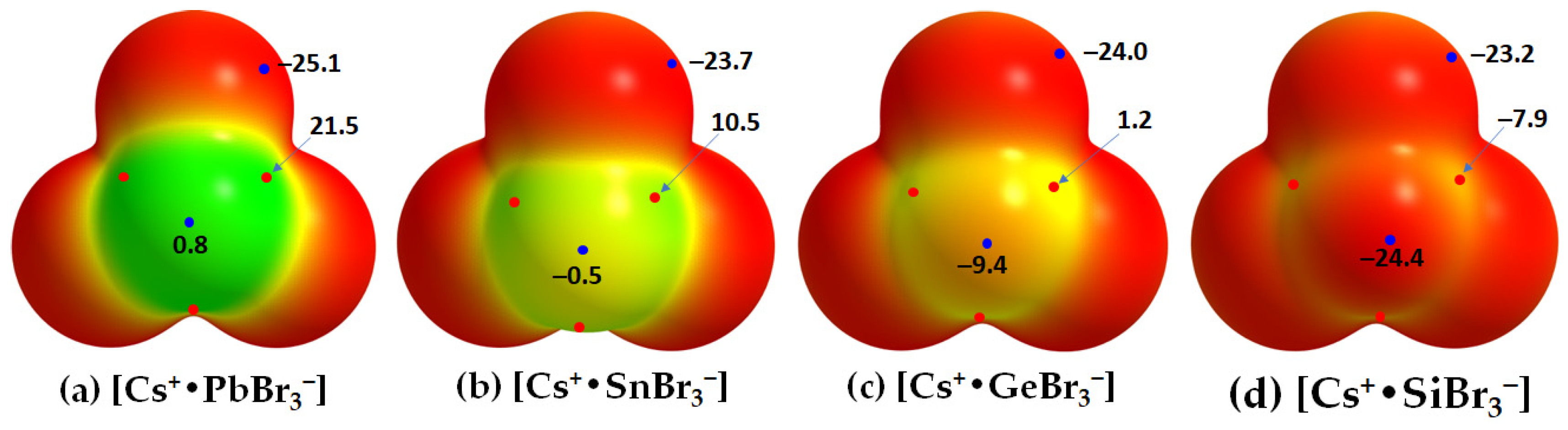
The cesium tetrel bromide perovskites, [CsTtBr3] (Tt = Pb, Sn, Ge), have been reported in different temperature crystalline phases, except for [CsSiBr3]; the structures of the high-temperature cubic phase are shown in Figure 5. This is probably because the surface of the Si atom along the Br–Si bond extensions is entirely negative, so the Si atom in the [Cs+•SiBr3] ion pair is unable to coulombically attract the nucleophilic bromide in a neighboring unit. This is supported by the MESP plots of [Cs+•TtBr3] shown in Figure 6. They suggest that the surface of Pb in [Cs+•PbBr3] is entirely positive along and around the outermost extension of the Br–Pb bonds (VS,max = 21.5 kcal mol−1 and VS,min = 0.8 kcal mol−1). That of Sn in [Cs+•SnBr3] is appreciably positive (VS,max = 10.5 kcal mol−1) along and weakly negative (VS,min = −0.5 kcal mol−1) around the outermost extension of the Br–Sn bonds. In [Cs+•GeBr3], the surface of Ge is weakly positive along and appreciably negative around the outermost extension of the Br–Ge bonds. However, in the case of [Cs+•SiBr3], the VS,max and VS,min on Si are all negative. For all four ion pairs, both the axial and equatorial portions of the Br atom along and around the Tt–Br extensions are nucleophilic (VS,min = −25.1 kcal mol−1).
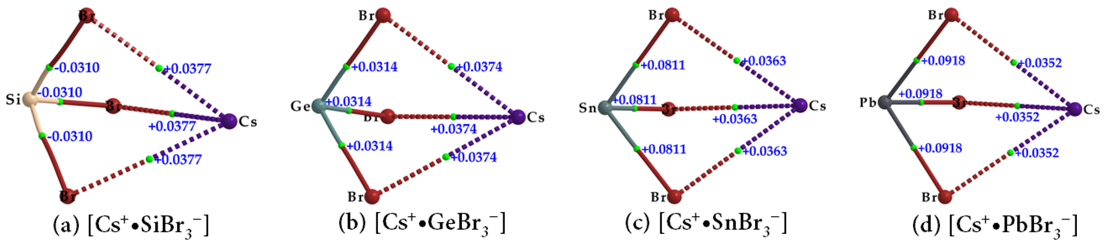
The topological charge density characteristics of the Tt–Br and Cs···Br bcps in the ion pairs [Cs+•TtBr3] (Tt = Si, Ge, Sn, Pb) (Figure 7a–d and Table 2) were found to be very similar to those observed for the Tt–I and Cs···I bcps in [Cs+•TtI3] (Table 1). However, the charge densities at the Tt–Br and Cs···Br bcps in [Cs+•TtBr3] were slightly larger; hence the strength of the Tt–Br and Cs···Br bonds are marginally stronger than the Tt–I and Cs···I bonds in [Cs+•TtI3]. The values of ∇2ρb are negative at the Si–Br bcps and positive at the Tt–Br (Tt = Ge, Sn, Pb) bcps, as seen in Figure 7 and listed in Table 2. The extent of charge transfer from the anion to the cation lies between 0.092 and 0.095 e.
(c) 
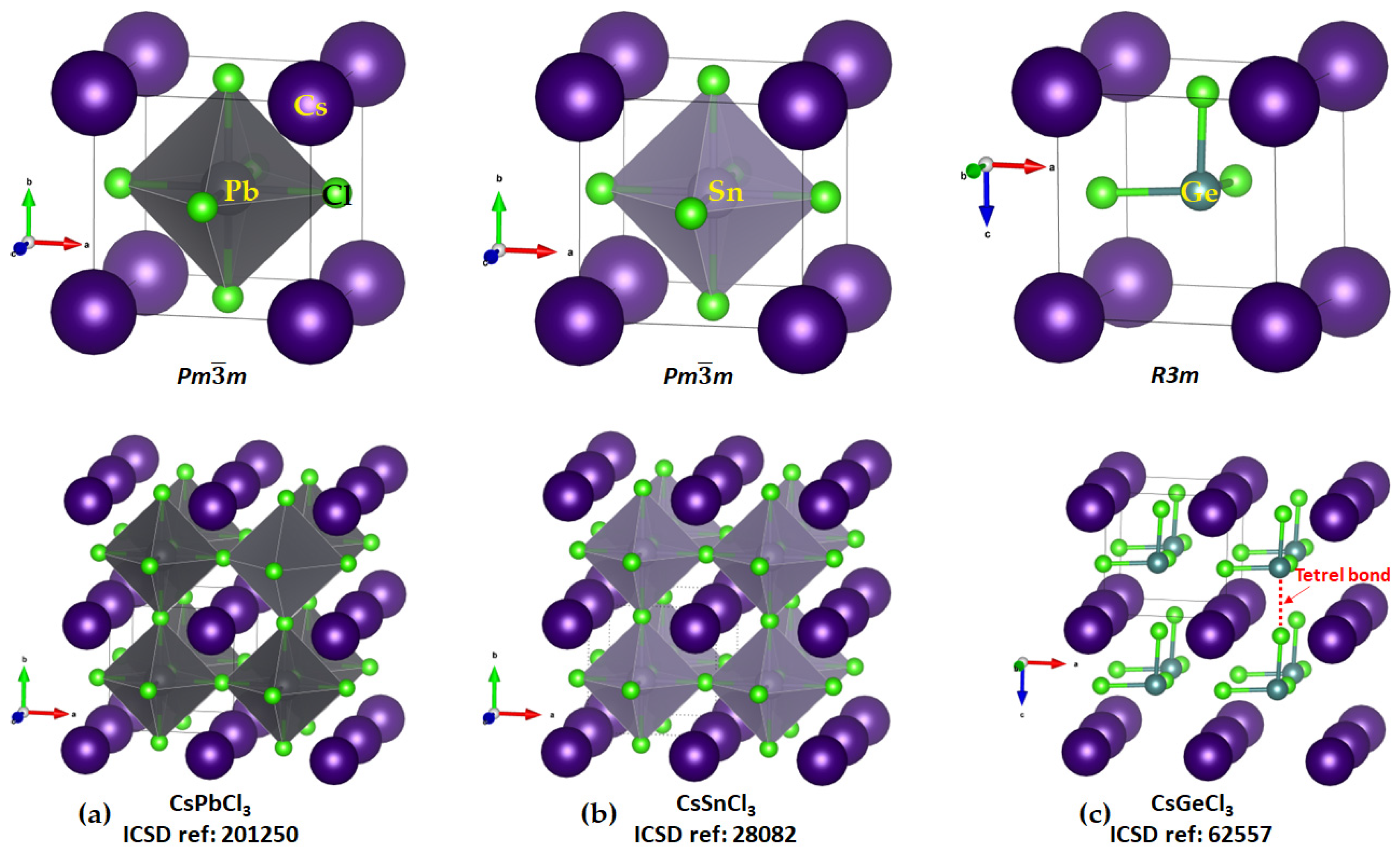
Cesium Tetrel Chloride Perovskites
The solid-state structures of CsTtCl3 (Tt = Ge, Sn, and Pb) are known, whereas that of [CsSiCl3] has not been reported. The connectivity between the [TtCl3] units that lead to the formation of the TtCl64− octahedra in the solid state are evident in all three structures shown in Figure 8a–c. The six Tt–Cl bonds in each polyhedron are equivalent in CsPbCl3 and CsSiCl3 (2.803 Å and 2.752 Å, respectively), showing that there is very little difference between the three Tt···Cl tetrel and three Tt–Cl coordinate bonds in these systems. In the case of CsGeCl3, three of the coordinate bonds are different to the other three; the three Ge–Cl coordinate bond distances are equivalent (2.415 Å each; Figure 8c, bottom) that are appreciably shorter than the three Ge···Cl tetrel bonds (r(Ge···Cl) = 3.036 Å and ∠Cl–Ge···Cl = 172.1°).
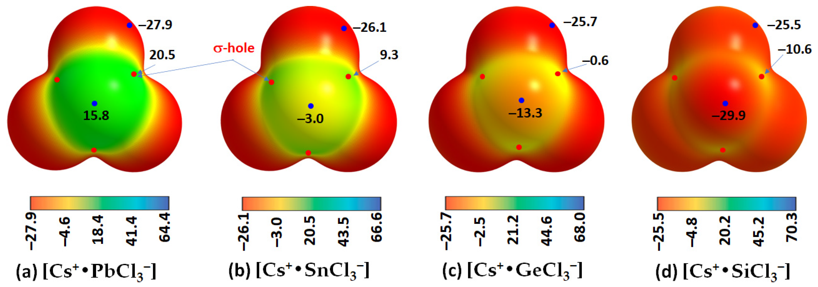
The fact that tetrel bonding plays a vital role in assembling the [TtCl3] units, which leads to the development of the cage-like inorganic framework, is evident from the results of the MESP analysis shown in Figure 9a–c for the ion pairs [Cs+•TtCl3]. Each of the three Cl–Tt bonds in each ion pair in [Cs+•TtCl3] (Tt = Pb, Sn) contains electron density-deficient regions along the Cl–Tt bond extensions (σ-holes) with positive electrostatic potentials. However, the potential is weakly negative in [Cs+•GeCl3] along the three Cl–Ge bond extensions (VS,max = −0.6 kcal mol−1 each, Figure 9c) and strongly negative along the three Cl–Si bond extensions in [Cs+•SiCl3] (VS,max = −10.6 kcal mol−1). It is clear from these results that the formation of CsTtCl3 (Tt = Pb, Sn) perovskite systems in 3D is expected when repeating units of [Cs+•TtCl3] ion pairs are in close proximity. This kind of assembly is unlikely when [Cs+•TtCl3] (Tt = Ge and Si) pairs are in close proximity because of coulombic repulsion between the halogen of an ion pair in close proximity to the negative tetrel site in a neighboring unit.
We, and others, have shown on several occasions that caution needs to be exercised when the potential of a σ-hole on an atom in a molecular entity is near neutral. In such a case, a higher isoelectronic density envelope may be required for mapping the potential since the choice of isoelectronic density envelope is arbitrary. Indeed, this is the case with [Cs+•GeCl3]. When the 0.001 a.u. isoelectronic density was used for mapping, the potential associated with each of the three σ-hole holes on Ge was weakly negative (VS,max = −0.6 kcal mol−1). However, when a 0.0015 a.u. isoelectron density was used, the VS,max of the σ-holes on the same atom was positive, VS,max = 4.4 kcal mol−1. The positive nature of the σ-hole on Ge explains why Ge in [Cs+•GeCl3] is capable of attracting the negative portion on the Cl atoms in a neighboring interacting ion-pair, thus leading to the formation of CsGeCl3 perovskite crystals in the crystalline phase [45]. By contrast, changing the value of the isodensity envelope did not change the negative character of the σ-holes on the Si atom along the Cl–Si bond extensions; thus, CsSiCl3 structures should not be formed when the ion pairs are repeated periodically.
There is a potential maximum on the Cs atom in the ion-pair that appears along the extension of the C3v axis. Its origin could be due to a weak Tt···Cs interaction in [Cs+•TtCl3] (Tt = Si, Ge, Sn, Pb), as well as the formation of three equivalent Cs···Cl alkali bonds. The surface of Cs is strongly positive relative to that of Tt in each [Cs+•TtCl3] (Tt = Si, Ge, Sn, Pb), which rationalizes why the cation lies at the center of the inorganic tetrel halide cage, thus interacting simultaneously with the lone-pair dominant regions of coordinate halides on each of the eight faces of eight octahedra (each sitting at the corner of a cage, Figure 8).
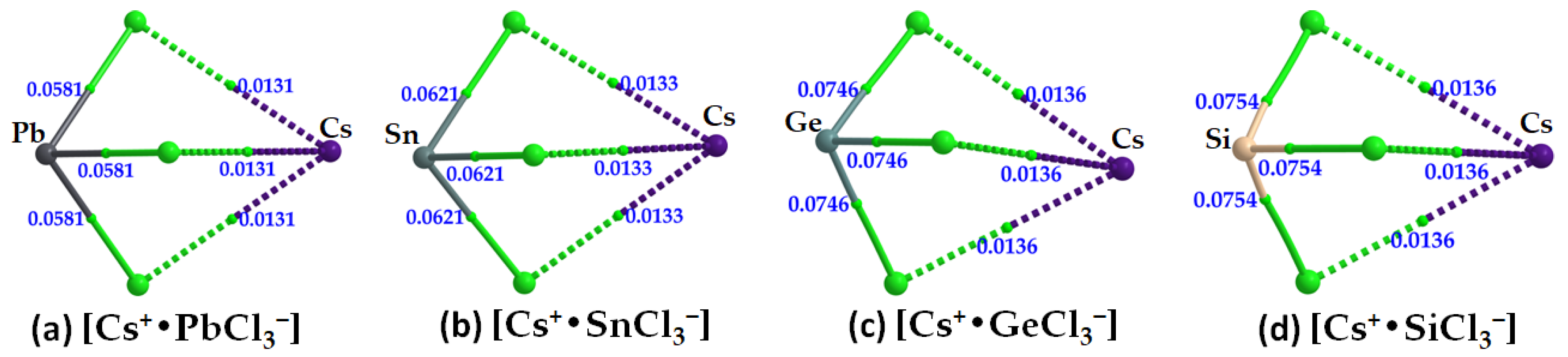
The formation of the alkali bonds in each ion pair, which is expected to mimic what occurs in the crystal (vide infra), is evident in the molecular graphs shown in Figure 10a–d and Table 3. The accumulation of charge density at the Cs···Cl bcps is weaker than that at the Tt–Cl bcps. For the latter, it trends as Pb–Cl < Sn–Cl < Ge–Cl < Si–Cl, and, with ∇2ρb > 0 and Hb < 0 (see values in Table 3), these bonds have mixed bonding character. This feature is clearly distinguishable from that of the alkali bonds that are largely electrostatic in character (∇2ρb > 0 and Hb > 0).
(d) 
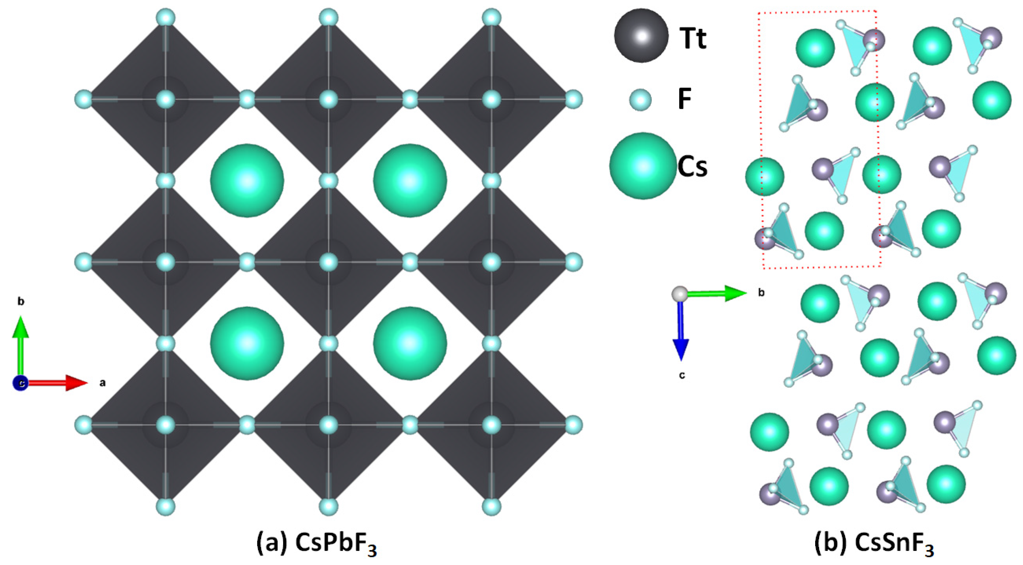
Cesium Tetrel Fluoride Perovskites
The structures of [Cs+•TtF3] are similar to the other cesium halide perovskite ion pairs discussed above. While the formation of these ion-pair systems is likely in the gas phase, they are not all stable in the crystalline phase. The instability of these perovskite structures is arguably due to the mismatch between the cavity of the fluoride-based inorganic perovskite cage formed from the repeating units of [TtF3] and the radial size of Cs+. This is not the case for CsPbF3, as seen in Figure 11a, the structure of which was reported in 1956 (cubic, Pm 3 m, ICSD ref: 30739 [59]) and 2001 (ICSD refs: 93438–93439). Smith et al. [60] have suggested that CsPbF3 is the only experimentally synthesized AMF3 fluoride perovskite with a polar ground state. Our search of the ICSD showed that CsSnF3 is not cubic (space group: P121/n1(14) [61]) and hence is a non-perovskite (Figure 11b). The authors of that study suggested that this system exhibits a ‘zero-dimensional’ crystal structure with isolated SnF3 anions separated by Cs+ cations; again, this is not surprising since the size of the cage formed by the repeating units of the SnF3 anion is too small to accommodate the guest Cs+. The ICSD does not contain structures of CsTtF3 (Tt = Ge, Sn), but it catalogues crystals such as Cs2GeF6 and Cs3GeF7, suggesting that the small size of fluoride, its low polarizability, and its high electronegativity lead it to form other types of crystal structures.
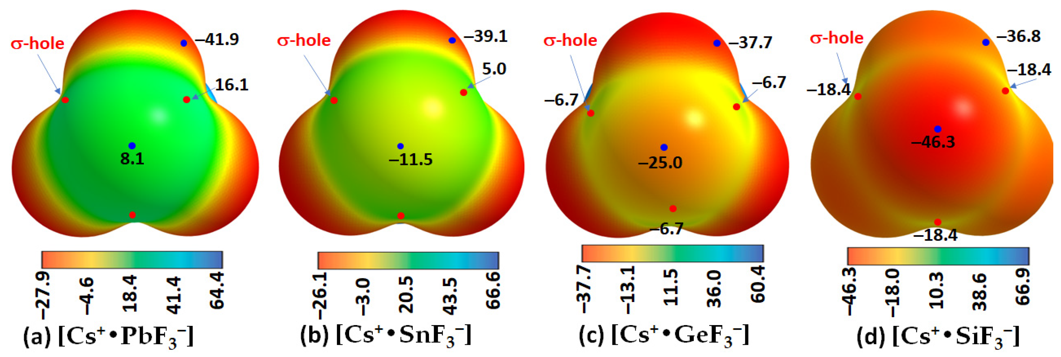
The results of our MESP calculations, shown in Figure 12, are in accordance with these rationalizations. They suggest the feasibility of the formation of [CsTtF3] (Tt = Pb and Sn) structures in the solid state since the surfaces of the Tt site in the [Cs+•TtF3] ion-pair systems are highly electrophilic, with the former more so than the latter. Specifically, the surface of Pb in [Cs+•PbF3] is entirely positive along and around the F–Pb bond extensions (Figure 12a), whereas that of Sn is positive only along the F–Sn bond extensions, while the region around the outer extension of the C3v axis is highly nucleophilic (Figure 12b). These positive sites are able to engage in a coulombic attraction with the negative site on the halogen of a neighboring unit to form structures of the types shown in Figure 11a,b, respectively. This is not the case when Tt = Ge and Si, the surfaces of which are entirely negative in [Cs+•GeF3] and [Cs+•SiF3] (see Figure 12c,d), respectively.
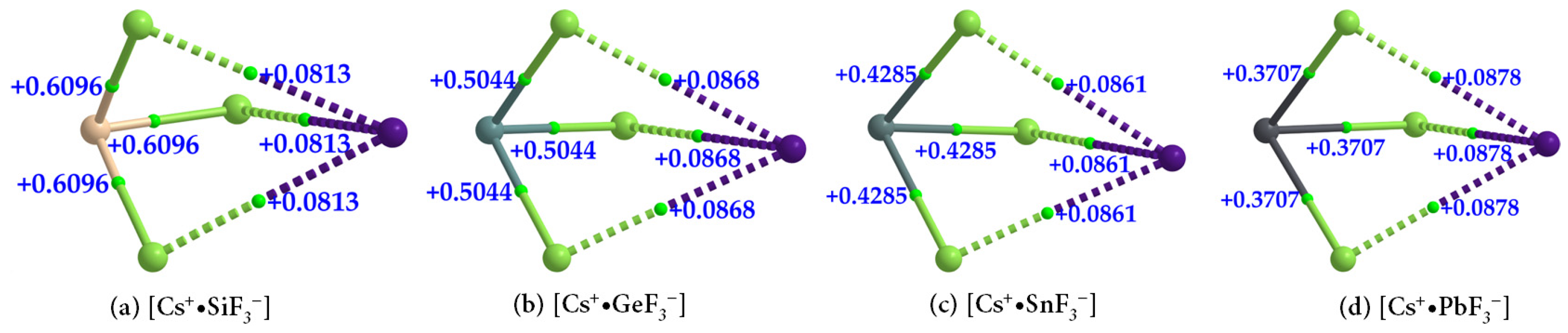
The formation of [Cs+•TtF3] (Tt = Si, Ge, Sn, and Pb) ion pairs is also evident in the QTAIM-based molecular graphs shown in Figure 13a–d. In all cases, the ∇2ρb at the Tt–F bcps are positive, showing that they are closed-shell interactions and appreciably ionic. The values of ∇2ρb at Tt–F bcps across the series follow the order [Cs+•SiF3] > [Cs+•GeF3] > [Cs+•SnF3] > [Cs+•PbF3], which parallels the trend in the negative Hb values for the same bonds (Table 4); Hb < 0 indicates that the bonds possess some covalency. The character of these coordinate interactions deduced from ∇2ρb and Hb values are not the same as that found for the Cs···F bcps. For the latter, the sign of both ∇2ρb and Hb are positive (Table 4), indicative of closed-shell (non-covalent) interactions.
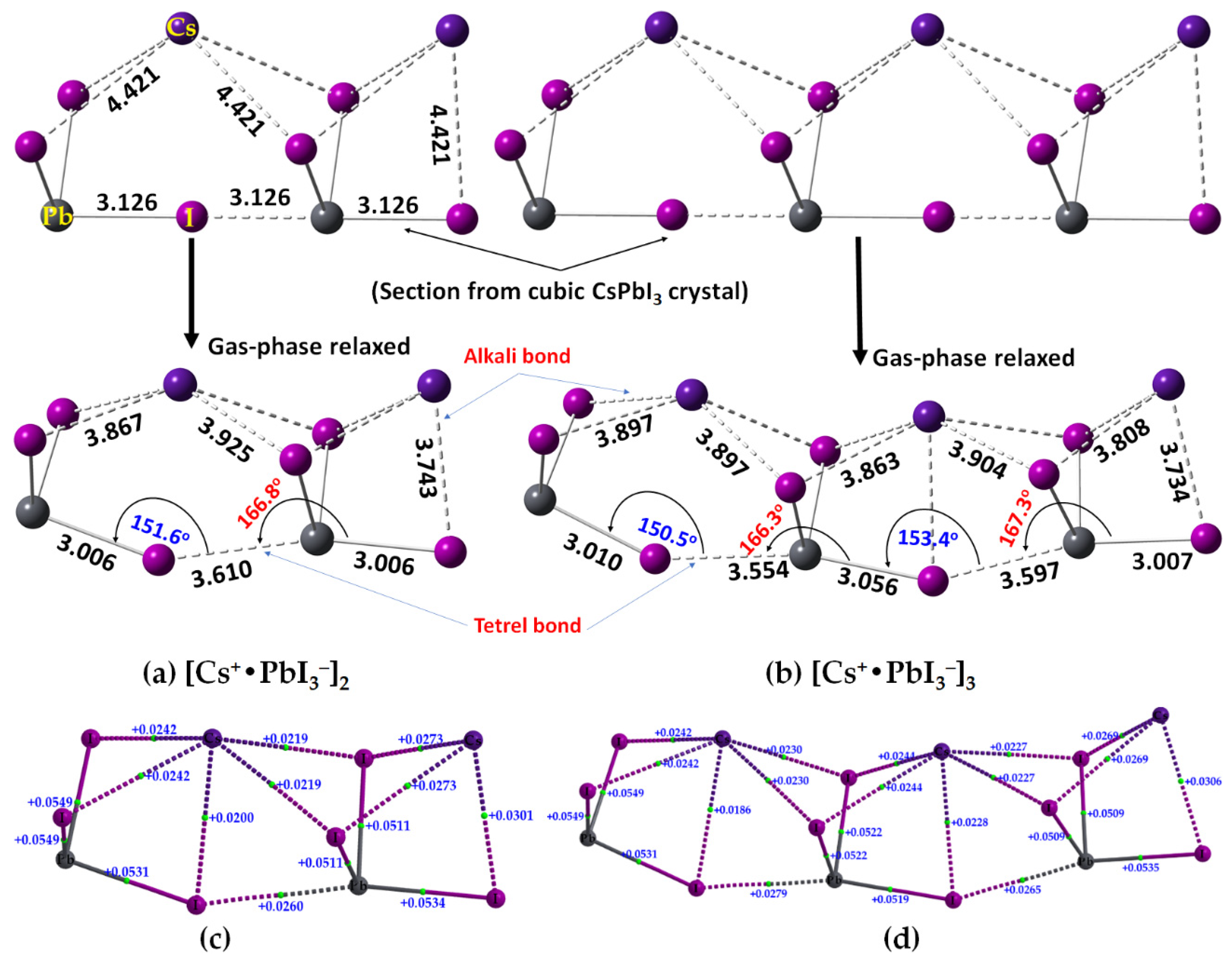
2.2. Oligomers of the [Cs+•PbI3] Ion Pair

We have sectioned the supercell structure of cubic CsPbI3 (Figure 2a, bottom), and extracted the binary, trinary, and tertiary clusters in 1D. These were fully energy minimized at the same level of theory, [ωB97XD/def2-TZVPPD]. The geometries of the resulting [Cs+•PbI3]2 dimer and [Cs+•PbI3]3 trimer are shown in Figure 14a,b, respectively, together with their corresponding QTAIM-based molecular graphs in Figure 14c,d, respectively. The Pb–I bonds found in the crystal (top) are significantly elongated in the gas phase (bottom) (cf. Figure 14a,b). The ∠Pb–I···Pb angles between the ion pairs in cubic CsPbI3 are linear, but non-linear in the gas-phase structure, leading to significant deformation passing from the solid-state structure to the gas-phase dimer and trimer. This discrepancy between the gas-phase and the solid-state geometries is not very surprising given that the role of packing forces is absent in the former. Interestingly, both the gas phase structures resemble the tilting of edge-sharing Pb–I chains in 1D, observed in the case of 3D CsPbI3. The ∠Pb–I···Pb angles are between 150° and 154° (Figure 14a,b, bottom), close to that seen between the edge-shared [PbI6]4− octahedra that are tilted relative to the corner-sharing octahedra in the low-temperature orthorhombic structure of CsPbI3 (∠Pb–I–Pb = 148.1° along the a-axis and 156.88° along the c-axis; ICSD ref: 17016 [49]). On the other hand, and as noted above, the tetrel bonds between the ion pairs are longer than the Pb–I coordinate bonds and are quasi-linear (∠I–Pb···I = 166.8° in [Cs+•PbI3]2 (Figure 14a) and 166.3° and 167.3° in [Cs+•PbI3]3 (Figure 14b). The physical chemistry of 1D CsPbI3 has been experimentally investigated [62,63,64]. It was shown that in the orthorhombic (Pnma) γ-phase, the PbI64− octahedra tilted around all three pseudocubic axes, aac+, which is different to the tilt observed in the tetragonal (P4/mbm), a0a0c+, β-phase [65], and the bandgap increases with an increase in the octahedral tilting when the temperature cools down, allowing for the emergence of β-CsPbI3 and γ-CsPbI3 [66].
The results of our QTAIM analysis for the [Cs+•PbI3]2 dimer (and [Cs+•PbI3]3 trimer) are given in Table 5. The Pb–I coordinate bonds in the [Cs+•PbI3]2 dimer (and [Cs+•PbI3]3 trimer) are characterized by ρb, ∇2ρb and −Hb values in the ranges of 0.0411–0.0472 (0.0379–0.0474), 0.0511–0.0116 (0.0509–0.0549), and 0.0071–0.007 (0.0058–0.0097) a.u., respectively. The corresponding values for the Cs···I alkali bonds were 0.0075–0.0116 (0.0069–0.0103), 0.0020–0.0301 (0.0186–0.0269), and −0.0008 (−0.0008) a.u., respectively. Although the former bonds possess a non-negligible amount of covalent character, the latter are purely electrostatic interactions. Their characteristics are comparable to those of I–Pb···I tetrel bonds (ρb = 0.0139 a.u., ∇2ρb = 0.0260 a.u., and −Hb = 0.0001 a.u). The [Cs+•PbI3]3 trimer has two non-equivalent I–Pb···I tetrel bonds (3.554 and 3.597 Å, Figure 14b), with ρb = 0.0152 (0.0143) a.u., ∇2ρb = 0.0279 (0.0265) a.u., and Hb ≈ 0.00001 a.u for the shorter (longer) bonds. The detailed nature of ∇2ρb at various bcps is shown in Figure 14c,d for the [Cs+•PbI3]2 dimer and [Cs+•PbI3]3 trimer, respectively.
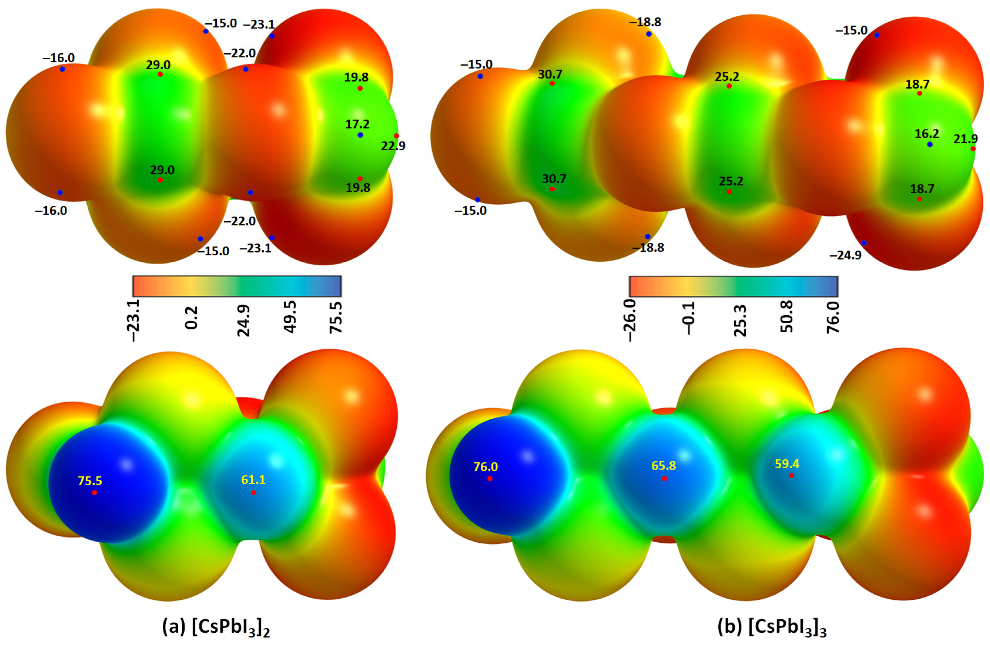
We confirmed the formation of I–Pb···I tetrel bonds in [Cs+•PbI3]2 and [Cs+•PbI3]3 oligomers using MESP results, Figure 15a,b. This signifies that one of the positive σ-holes on the surface of Pb in the [Cs+•PbI3] ion pair (Figure 4a) is annihilated because it is engaged with the entirely negative (iodide) site in the neighboring ion pair through an electrostatic interaction, leading to the formation of an I–Pb···I tetrel bond. This causes a change in the potential minima and maxima on the surfaces of the two ion-pair entities at the equilibrium geometry of the oligomer.
An interesting feature of the [Cs+•PbI3]4 tetramer is that the Pb–I bonds are no longer equivalent, as found in cubic CsPbI3 in 3D (Figure 4a), but comparable with those found in the [Cs+•PbI3]2 dimer and [Cs+•PbI3]3 trimer (vide supra). Again, this is the result of the gas phase, where the role of the periodic boundary condition is nullified and no packing forces act on the system. The [Cs+•PbI3] ion pairs are free to interact with each other in the gas phase at 0 K, causing the linear Pb–I–Pb bonds found in the cubic structure of CsPbI3 to change appreciably in a manner so as to adopt a significantly distorted geometry very similar to that observed in the low-temperature orthorhombic phase of the system (vide supra).
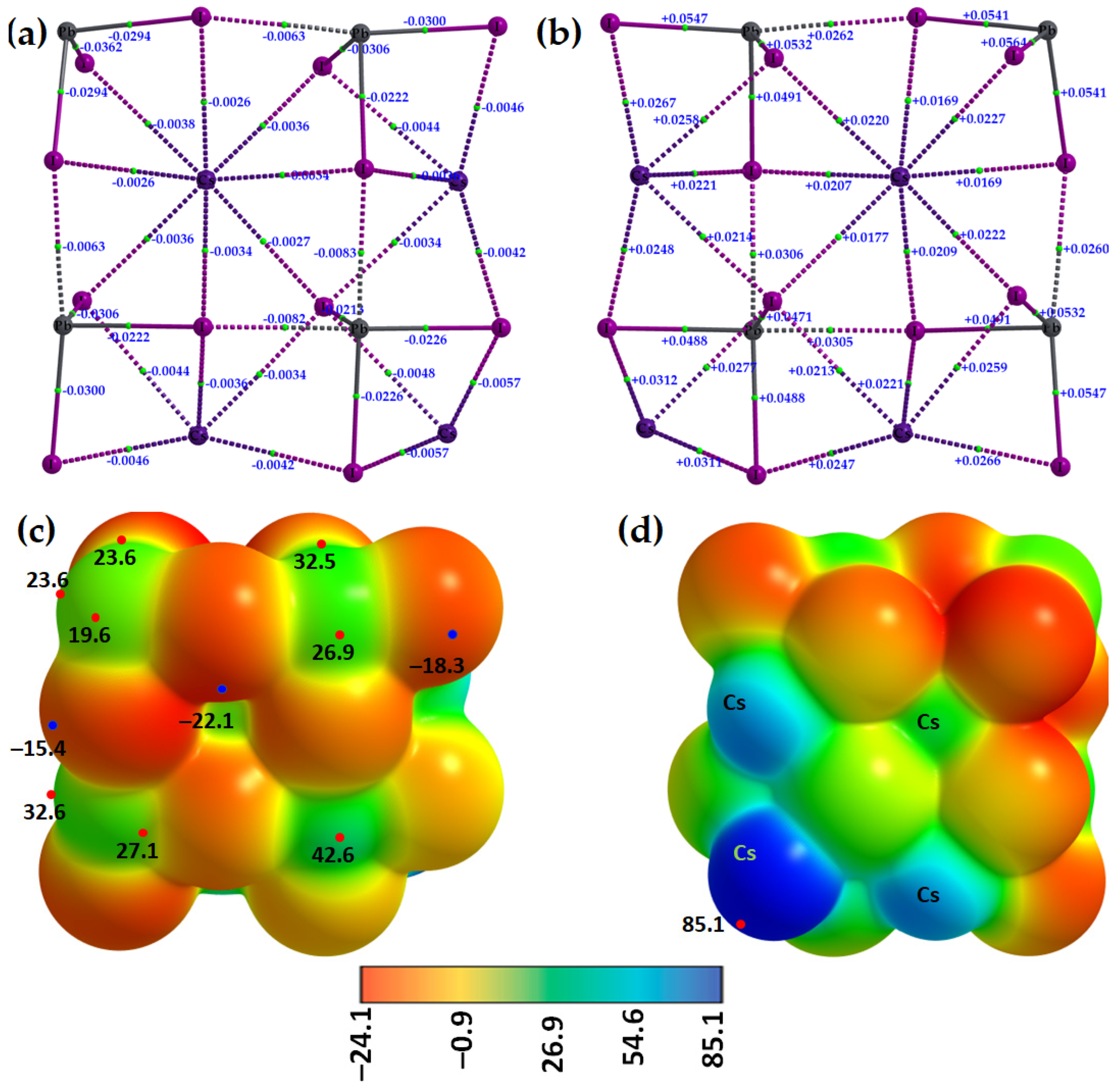
The molecular graphs of two different orientations of the [Cs+•PbI3]4 tetramer are shown in Figure 16a (with values of the potential energy density, Vb) and Figure 16b (∇2ρb at the bcps). Regardless of the nature of the bonding interactions involved, the sign of Vb is always negative and, hence, stabilizing. Values of ∇2ρb are all positive, indicating that the bonding interactions are of the closed-shell type. While the relationship Eb(QTAIM) = −½ Vb may be empirical, it suggests that the I–Pb···I tetrel bond is stronger than the Cs···I alkali bond (Eb(QTAIM) values of 4.0 kcal mol−1 vs. 1.5 kcal mol−1).
The formation of both Pb···I tetrel bonds and Cs···I alkali bonds between four units of the [Cs+•PbI3] ion pairs in the [Cs+•PbI3]4 tetramer can also be understood from the MESP plots shown in Figure 16c,d. Upon assembly, the σ-hole on three Pb atoms in three ion pairs of the tetramer is annihilated upon its attractive engagement with the iodide atom of a neighboring ion pair, thus forming Pb···I tetrel bonds. The four tetrel centers are positive (see the four green regions in Figure 16c), and one of them, which is not involved in the formation of the tetrel bond (Figure 16c, top left), conceives three σ-holes on its surface; these can accept nucleophiles when in close proximity to another three ion pairs. By contrast, the Cs ions are highly electrophilic. These unequivocally provide evidence of the fact that the formation of the 3D network of the cage-like structures of cesium tetrel halide perovskites are the result of σ-hole-centered tetrel-bonded interactions between [PbI3] anions in the presence of Cs+. The physical chemistry of tetrel bonds also plays a significant role in stabilizing 1D CsPbI3, a material suitable for stable X-ray detection (sensitivity = 2.37 mC·Gy−1·cm−2, resistivity = 7.4 × 10⁹ Ω·cm, and carrier mobility–lifetime product = 3.63 × 10⁻³ cm2·V−1 [62]).

2.3. Stabilization Energy

The interaction energies and intermolecular bond distances between [Cs+] and [TtX3] for all the sixteen [Cs+•TtX3] ion pairs are summarized in Table 5. They are very large compared to ordinary non-covalent interactions but comparable with the binding energies of anion-molecule interactions. The charge-assisted tetrel bonds reported recently had energies (in kcal mol−1) as large as −93.43 [I4Ge···F], –112.15 ([I4Si···F]), and −84.05 ([I4Pb···F]) with [CCSD/def2-TZVPPD], which were very close to those calculated with [ωB97X-D/def2-TZVPPD] [67]. Large interaction energies were also reported for tetrel bonds [62], halogen bonds [68], hydrogen bonds [68], and pnictogen bonds [69] in other anion–molecule complexes. The large interaction energies, Eb and Eb(BSSE), summarized in Table 5 are expected since a large part of the contribution arises from coulombic interaction between two interacting charged moieties. The binding energies are also comparable with those reported for similar halide perovskite ion-pairs at the [CCSD(T)/cc-pVTZ] level of theory [70].
For a series with a given halogen derivative [Cs+•TtX3], the interaction energies increase as the atomic size of the tetrel derivative increases (Si < Ge < Sn < Pb). This trend agrees well with the increasing strength of the σ-hole on Tt across the series for a given type of halogen derivative (see, for examples, Figure 4 for [Cs+•TtI3], Figure 6 for [Cs+•TtBr3], Figure 9 for [Cs+•TtCl3], and Figure 12 for [Cs+•TtF3]).
For a given tetrel derivative, the interaction energy increases as the atomic size of the halogen increases ([Cs+•TtF3] > [Cs+•TtCl3] > [Cs+•TtBr3] > [Cs+•TtI3]). For each series shown in Table 6, the largest interaction energy is calculated for cesium lead halide perovskite ion pairs, probably a consequence of the high polarizability of Pb compared to the other three tetrel derivatives. Among all the ion pairs examined, the ion pair of cesium lead fluoride perovskite, [Cs+•PbF3], is the strongest. This is expected since fluorine in the inorganic moiety [PbF3] is the most electronegative and electron-withdrawing of the halogens; hence, it strongly interacts with Cs+, which, therefore, cannot create strong σ-holes on Pb in [Cs+•PbF3]. All these trends remain valid regardless of whether Eb or Eb(BSSE) is considered since the BSSE is calculated to be very small.
As a rule of thumb, it is expected that the interaction energy increases as the intermolecular distance between interacting moieties decreases. However, this is not the case with the ion pairs explored in this study, where we find the opposite trend. The interaction energy for a given halogen derivative between [Cs+] and [TtX3] increases when increasing the intermolecular distance between them (Table 6). This is not the case for ion pairs with a given tetrel derivative; here, the interaction energy increases ([Cs+•TtF3] > [Cs+•TtCl3] > [Cs+•TtBr3] > [Cs+•TtI3]) when decreasing the intermolecular bond distance ([Cs+•TtF3] < [Cs+•TtCl3] < [Cs+•TtBr3] < [Cs+•TtI3]), as seen in Table 5. The interaction energy associated with the alkali bonds as a function of bond distance for [Cs+•TtX3] is shown in Figure 17.
The uncorrected binding energy of the tetrel bonds in the [Cs+•PbX3]2 dimer, [Cs+•PbX3]3 trimer, and [Cs+•PbX3]4 tetramer shown in Figure 15 and Figure 16 are −20.7, −21.3, and −22.4 kcal mol−1, respectively. These were obtained by subtracting the total electronic energy of the oligomer from two, three, and four times the total electronic energy of the [Cs+•PbX3] ion pair, indicating that the binding energy is nearly additive. However, these may not be solely due to the tetrel bonds since each Cs+ ion in each [Cs+•PbX3] ion pair also contributes to the binding of the resulting oligomer through Cs···I alkali bonds. From these results, it is apparent that the empirical relationship Eb(QTAIM) = −½Vb is not applicable to tetrel bond energies since it largely underestimates the magnitudes. The relationship might be useful for some hydrogen-bonded systems [71], but may not be generalized to other non-covalent interactions such as the tetrel bonds explored in this work.

3. Discussion

This study was undertaken to reveal the underlying reasons why the TtX3 units interact to form the inorganic cage-like tetrel halide frameworks of 3D cesium halide perovskites. We have shown that the connectivity between the TtX3 anions that lead to the formation of the 3D infinite inorganic framework, [TtX3], is driven by the inorganic cation, Cs+, through the effects of both electrostatic polarization and coulombic attraction. The joint involvement of electrostatic polarization and coulombic attraction causes redistribution of the charge density profile on the electrostatic surfaces of the molecular tetrel halide perovskites, resulting in the development of positive σ-holes on the Tt atom in the TtX3 anions in the ion pairs [Cs+•TtX3] (Tt = Ge, Sn, Pb). This is accompanied by appreciable amount of charge transfer from the halides of the TtX3 anions to Cs+ when they are in close proximity. The σ-holes formed on the Tt atom, therefore, are able to simultaneously attract the negative halogens from three interacting TtX3 anions, thus leading to the formation of TtX64− octahedra, the underlying framework of the 3D CsTtX3 cesium tetrel halide perovskites. The tetrel bonds formed are hidden between the anion moieties in the solid state structures, and to demonstrate their presence requires appropriate theoretical methods such as the QTAIM and MESP models.
There has been a failure to experimentally produce 3D tetrel halide perovskites when Tt = Si. We have explained this failure using the results of the MESP model. The underlying reason is the lack of an appreciable positive potential on the Si atom along the X–Si bond extensions in the molecular ion pair, [Cs+•SiX3]. Therefore, Si is incapable of engaging with the negative halogen in a neighboring unit because of the columbic repulsion between them.
Although the fluorinated ion-pair systems displayed electrophilic regions when Tt = Pb and Sn, the latter does not form a perovskite structure because of the small size of the cavity formed by repeating [SnF3] units, a cavity that cannot accommodate the inorganic cation. This might explain why CsSnF3 crystalizes in low-dimension. By contrast, the results of the MESP model have showed that CsGeF3 and CsSiF3 perovskites cannot be formed in the crystalline phase because the Tt along the F–Tt bond extensions in the [Cs+•SiF3] (Tt = Ge, Si) ion pair has negative σ-holes. These negative σ-holes would repel the entirely negative fluorine atom(s) in a neighboring interacting unit(s), preventing the formation of Tt···F (Tt = Ge, Si) tetrel bonds. This also explains why the crystal structures of CsSiF3 (Tt = Ge, Si) are unknown.

4. Materials and Methods

Computational Details

The geometries of sixteen ion pairs, [Cs+•TtX3] (Tt = Pb, Sn, Ge, Si; X = I, Br, Cl, F), were fully energy-minimized, followed by frequency calculations. The most stable conformer was considered. The ωB97XD functional [72] as implemented in the Gaussian 16 code [73], together with the def2-TZVPPD basis set retrieved from the EMSL basis set library [74], was employed. ωB97XD is known as a range-separated functional and is capable of capturing both short-range and long-range interactions. Minenkov et al. have demonstrated that the ωB97XD functional outperforms other commonly used DFT functionals (PBE and TPSS, M06 and M06L) and also produces relatively small statistical errors when considering the overall structure and inter-nuclear distances [75]. All ion-pair geometries were at an energy minimum, confirmed by positive harmonic vibrational frequencies. Default convergence criteria (viz. tight SCF convergence and ultrafine integration grid) were invoked.
Similar calculations, as above, were also performed for a dimer, a trimer, and a tetramer of [Cs+•PbI3], which we refer to as the [Cs+•PbI3]n (n = 2, 3, 4) oligomers, to demonstrate the charge density topologies of alkali and tetrel bonding interactions responsible for the formation of the 3D network of CsPbI3. The nature of physical chemistry revealed for these systems might be transferable to other oligomers when Pb in [Cs+•PbI3]n (n = 2, 3, 4) is replaced, for example, by Sn and Ge.
Relativistic spin-orbit coupling (SOC) is an important feature of tetrel halide perovskite semiconductors containing heavy atoms such as Pb because its inclusion affects the band structure without affecting the crystal geometry [76]. In particular, the inclusion of SOC can affect the direct character of the band gap transition between the extrema of valence and conduction band states, especially for periodic systems containing Pb [77]. This effect, called the Rashba–Dresselhaus effect [78], is observed specifically in non-centrosymmetric environments and can be directly measured by angle-resolved X-ray photoemission spectroscopy. However, because our calculations are aperiodic and do not involve the calculation of the band structures of the molecular entities considered, the effect of SOC was not taken into account, in line with several recent studies [67,79,80,81,82].
The uncorrected and BSSE-corrected interaction energies (Eb and Eb(BSSE), respectively) of the ion pairs [Cs+•TtX3] were calculated using Equations (1) and (2), respectively. BSSE refers to the basis set superposition error, evaluated using the counterpoise procedure of Boys and Bernardi [83], and ET [Cs+•TtX3], ET [Cs+] and ET [TtX3] are the total electronic energies of the respective species.
Eb [Cs+•TtX3] = ET [Cs+•TtX3] − ET [Cs+] − ET [TtX3]
Eb (BSSE) = Eb [Cs+•TtX3] + BSSE
QTAIM [84] calculations were performed at the same level of theory described above. Properties such as the charge density (ρb), the Laplacian of the charge density (∇2ρb), and the total energy density (Hb) at the (3, −1) bond critical points (bcps), critical points where the gradients of ρ(r) vanish, were analyzed. The latter two properties at bcps provide insight into the closed-shell and/or open-shell nature of an interaction between a pair of atomic basins in molecular and intermolecular entities. For instance, the positive and negative signs of ∇2ρb were utilized to demonstrate the closed- and open-shell interactions, respectively, which were identified between the inorganic anion and cation and between the anions [85,86,87,88,89]. Similarly, the positive and negative signs of Hb (Hb = Gb + Vb) were utilized to provide insight into the absence and presence of a covalent interaction between the corresponding moieties, respectively [86,90]. This relies on the fact that a positive Hb indicates a prevalence of the gradient kinetic energy density Gb over the potential energy density Vb, which is typical of non-covalently bonded interactions [91,92,93]. We have also used the empirical formula Eb(QTAIM) = −½ Vb [71] to calculate the binding energy associated with the various non-covalent interactions identified in the ion-pairs investigated.
The MESP calculations [94,95,96,97,98,99] were performed with [ωB97XD/def2-TZVPPD], utilizing the fully relaxed geometries of the ion pairs and oligomers. The signs and magnitudes of the potential extrema were computed using the 0.001 a.u. isoelectronic density envelope of the ion pairs. The magnitude of potential is a measure of the strength, whereas its (positive and negative) signs were used to provide insight into regions of charge density depletion and concentration on the electrostatic surfaces of the ion pairs, respectively. That is, th corresponding signs of the local most maxima and minima of potential (VS,max and VS,min, respectively) were utilized to arrive at these conclusions. For instance, the sign of both VS,max and VS,min can either be positive or negative, or sometimes even neutral. When positive, it is generally assumed that the region on the surface that accompanies this is electrophilic and, hence, may be suitable for accepting electron density from an interacting electron donor in close proximity. When it is negative, the region on the surface of the molecular entity that features this is nucleophilic and, hence, may be capable of donating electron density to an interacting electrophile when in close vicinity. However, it should be kept in mind that all negative or positive sites on the surface of the molecular entity may or may not always be capable of engaging in attractive interaction with a region that features the opposite reactive profile.
An electrophilic σ-hole on atom A lying opposite to the R–A covalent bond is characterized when the sign VS,max is positive (VS,max > 0) [97,100]. Similarly, a nucleophilic σ-hole on atom A in R–A is observed when VS,max is negative (VS,max < 0) [97,100]. For instance, the σ-hole on F in H–F and H3C–F is negative, whereas that on X in H3C–X, X3C–X, and F5CX (X = Cl, Br, I) is positive. The underlying equation details and applicability of the MESP model to understand non-covalent interactions have appeared in several studies [67,95,96,99,101,102,103,104,105,106,107], hence we do not repeat them here.
AIMAll [108] and MultiWfn [109] codes were used for MESP and QTAIM analyses.

Author Contributions

Conceptualization, project design, and project administration, P.R.V.; formal analysis and investigation, P.R.V. and A.V.; supervision, P.R.V.; writing—original draft, P.R.V. and A.V.; writing—review, editing, and validation, P.R.V., H.M.M., A.V. and K.Y. All authors have read and agreed to the published version of the manuscript.

Funding

This research received no external funding.

Institutional Review Board Statement

Not applicable.

Informed Consent Statement

Not applicable.

Data Availability Statement

This research did not report any data.

Acknowledgments

This work was entirely conducted using various laboratory facilities provided by the University of Tokyo and the University of the Witwatersrand. P.R.V. is currently affiliated with the University of the Witwatersrand (SA) and Nagoya University (Japan). A.V. is currently affiliated with Tokyo University of Science (Japan). K.Y. is currently affiliated with Yokohama City University and Kyoto University (Japan). H.M.M. thanks the National Research Foundation, Pretoria, South Africa, and the University of the Witwatersrand for funding.

Conflicts of Interest

The authors declare no conflict of interest. The funders had absolutely no role in the design of the study; in the collection, analyses, or interpretation of data; in the writing of the manuscript; or in the decision to publish the results.

References

  1. Liang, J.; Qi, Y.B. Recent progress on all-inorganic metal halide perovskite solar cells. Mater. Today Nano 2021, 16, 100143. [Google Scholar] [CrossRef]
  2. Akkerman, Q.A.; Manna, L. What Defines a Halide Perovskite? ACS Energy Lett. 2020, 5, 604–610. [Google Scholar] [CrossRef] [PubMed] [Green Version]
  3. Varadwaj, P.R.; Marques, H.M. Physical and optoelectronic features of lead-free A2AgRhBr6 (A = Cs, Rb, K, Na, Li) with halide double perovskite composition. J. Mater. Chem. C 2020, 8, 12968–12983. [Google Scholar] [CrossRef]
  4. Bhandari, K.P.; Ellingson, R.J. An Overview of Hybrid Organic–Inorganic Metal Halide Perovskite Solar Cells. In A Comprehensive Guide to Solar Energy Systems; Letcher, T.M., Fthenakis, V.M., Eds.; Academic Press: London, UK, 2018; pp. 233–254. [Google Scholar]
  5. Varadwaj, A.; Varadwaj, P.R.; Marques, H.M.; Yamashita, K. Halogen in materials design: Revealing the nature of hydrogen bonding and other non-covalent interactions in the polymorphic transformations of methylammonium lead tribromide perovskite. Mater. Today Chem. 2018, 9, 1–16. [Google Scholar] [CrossRef] [Green Version]
  6. Varadwaj, P.R.; Varadwaj, A.; Marques, H.M.; Yamashita, K. Significance of hydrogen bonding and other noncovalent interactions in determining octahedral tilting in the CH3NH3PbI3 hybrid organic-inorganic halide perovskite solar cell semiconductor. Sci. Rep. 2019, 9, 50. [Google Scholar] [CrossRef] [Green Version]
  7. Varadwaj, A.; Varadwaj, P.R.; Marques, H.M.; Yamashita, K. The Pnictogen Bond, Together with Other Non-Covalent Interactions, in the Rational Design of One-, Two- and Three-Dimensional Organic-Inorganic Hybrid Metal Halide Perovskite Semiconducting Materials, and Beyond. Int. J. Mol. Sci. 2022, 23, 8816. [Google Scholar] [CrossRef] [PubMed]
  8. Kamat, P.V. Organometal halide perovskites for transformative photovoltaics. J. Am. Chem. Soc. 2014, 136, 3713–3714. [Google Scholar] [CrossRef]
  9. Wang, X.; Li, M.; Zhang, B.; Wang, H.; Zhao, Y.; Wang, B. Recent progress in organometal halide perovskite photodetectors. Org. Electron. 2018, 52, 172–183. [Google Scholar] [CrossRef]
  10. Yuan, J.; Liu, H.; Wang, S.; Li, X. How to apply metal halide perovskites to photocatalysis: Challenges and development. Nanoscale 2021, 13, 10281–10304. [Google Scholar] [CrossRef]
  11. Peighambardoust, N.S.; Sadeghi, E.; Aydemir, U. Lead Halide Perovskite Quantum Dots for Photovoltaics and Photocatalysis: A Review. ACS Appl. Nano Mater. 2022, 5, 14092–14132. [Google Scholar] [CrossRef]
  12. Ghosh, S.; Shankar, H.; Kar, P. Recent developments of lead-free halide double perovskites: A new superstar in the optoelectronic field. Mater. Adv. 2022, 3, 3742–3765. [Google Scholar] [CrossRef]
  13. Zhao, X.-G.; Yang, D.; Ren, J.-C.; Sun, Y.; Xiao, Z.; Zhang, L. Rational Design of Halide Double Perovskites for Optoelectronic Applications. Joule 2018, 2, 1662–1673. [Google Scholar] [CrossRef] [Green Version]
  14. Heidari Gourji, F.; Velauthapillai, D. A Review on Cs-Based Pb-Free Double Halide Perovskites: From Theoretical and Experimental Studies to Doping and Applications. Molecules 2021, 26, 2010. [Google Scholar] [CrossRef] [PubMed]
  15. Kakavelakis, G.; Gedda, M.; Panagiotopoulos, A.; Kymakis, E.; Anthopoulos, T.D.; Petridis, K. Metal Halide Perovskites for High-Energy Radiation Detection. Adv. Sci. 2020, 7, 2002098. [Google Scholar] [CrossRef] [PubMed]
  16. Mazumdar, S.; Zhao, Y.; Zhang, X. Stability of Perovskite Solar Cells: Degradation Mechanisms and Remedies. Front. Electron. 2021, 2, 712785. [Google Scholar] [CrossRef]
  17. Lin, H.; Zhou, C.; Tian, Y.; Siegrist, T.; Ma, B. Low-Dimensional Organometal Halide Perovskites. ACS Energy Lett. 2018, 3, 54–62. [Google Scholar] [CrossRef] [Green Version]
  18. Sun, S.; Lu, M.; Gao, X.; Shi, Z.; Bai, X.; Yu, W.W.; Zhang, Y. 0D Perovskites: Unique Properties, Synthesis, and Their Applications. Adv. Sci. 2021, 8, 2102689. [Google Scholar] [CrossRef] [PubMed]
  19. Aebli, M.; Benin, B.M.; McCall, K.M.; Morad, V.; Thöny, D.; Grützmacher, H.; Kovalenko, M.V. White CsPbBr3: Characterizing the One-Dimensional Cesium Lead Bromide Polymorph. Helv. Chim. Acta 2020, 103, e2000080. [Google Scholar] [CrossRef]
  20. Li, Q.; Lian, T. Ultrafast Charge Separation in Two-Dimensional CsPbBr3 Perovskite Nanoplatelets. J. Phys. Chem. Lett. 2019, 10, 566–573. [Google Scholar] [CrossRef]
  21. Zhang, L.; Liang, W. How the Structures and Properties of Two-Dimensional Layered Perovskites MAPbI3 and CsPbI3 Vary with the Number of Layers. J. Phys. Chem. Lett. 2017, 8, 1517–1523. [Google Scholar] [CrossRef]
  22. Kojima, K.; Teshima, Y.; Shirai, Y.; Miyasaka, T. Organometal halide perovskites as visible-light sensitizers for photovoltaic cells. J. Am. Chem. Soc. 2009, 131, 6050–6051. [Google Scholar] [CrossRef] [PubMed]
  23. Varadwaj, P.R. Methylammonium Lead Trihalide Perovskite Solar Cell Semiconductors Are Not Organometallic: A Perspective. Helv. Chim. Acta 2017, 100, e1700090. [Google Scholar] [CrossRef]
  24. De Angelis, F.; Kamat, P.V. Riding the New Wave of Perovskites. ACS Energy Lett. 2017, 2, 922–923. [Google Scholar] [CrossRef]
  25. Zhang, W.; Eperon, G.E.; Snaith, H.J. Metal halide perovskites for energy applications. Nat. Energy 2016, 1, 16048. [Google Scholar] [CrossRef]
  26. Yu, S.; Liu, P.; Xiao, S. A review of main characterization methods for identifying two-dimensional organic–inorganic halide perovskites. J. Mat. Sci. 2021, 56, 11656–11681. [Google Scholar] [CrossRef]
  27. Tang, D.-M.; Erohin, S.V.; Kvashnin, D.G.; Demin, V.A.; Cretu, O.; Jiang, S.; Zhang, L.; Hou, P.-X.; Chen, G.; Futaba, D.N.; et al. Semiconductor nanochannels in metallic carbon nanotubes by thermomechanical chirality alteration. Science 2021, 374, 1616–1620. [Google Scholar] [CrossRef] [PubMed]
  28. Varadwaj, A.; Varadwaj, P.R.; Yamashita, K. Revealing the Cooperative Chemistry of the Organic Cation in the Methylammonium Lead Triiodide Perovskite Semiconductor System. ChemistrySelect 2018, 3, 7269–7282. [Google Scholar] [CrossRef]
  29. Motta, C.; El-Mellouhi, F.; Kais, S.; Tabet, N.; Alharbi, F.; Sanvito, S. Revealing the role of organic cations in hybrid halide perovskite CH3NH3PbI3. Nat. Commun. 2015, 6, 7026. [Google Scholar] [CrossRef] [Green Version]
  30. Matheu, R.; Ke, F.; Breidenbach, A.; Wolf, N.R.; Lee, Y.; Liu, Z.; Leppert, L.; Lin, Y.; Karunadasa, H.I. Charge Reservoirs in an Expanded Halide Perovskite Analog: Enhancing High-Pressure Conductivity through Redox-Active Molecules. Angew. Chem. Int. Ed. 2022, 61, e202202911. [Google Scholar] [CrossRef]
  31. Liu, S.; Wang, J.; Hu, Z.; Duan, Z.; Zhang, H.; Zhang, W.; Guo, R.; Xie, F. Role of organic cation orientation in formamidine based perovskite materials. Sci. Rep. 2021, 11, 20433. [Google Scholar] [CrossRef]
  32. Sung, W.; Müller, C.; Hietzschold, S.; Lovrinčić, R.; Gallop, N.P.; Bakulin, A.A.; Nihonyanagi, S.; Tahara, T. Preferred orientations of organic cations at lead-halide perovskite interfaces revealed using vibrational sum-frequency spectroscopy. Mater. Horiz. 2020, 7, 1348–1357. [Google Scholar] [CrossRef]
  33. Cadillo, A.T.; Vargas, A.; Roa, A.; Garay-Tapia, A.M. The role of organic cations as additives in photovoltaic perovskites. In ChemRxiv; Cambridge Open Engage: Cambridge, UK, 2022; Available online: https://chemrxiv.org/engage/chemrxiv/article-details/62be0385d66f68ee9bb89111 (accessed on 2 April 2023).
  34. Teng, Q.; Shi, T.-T.; Tian, R.-Y.; Yang, X.-B.; Zhao, Y.-J. Role of organic cations on hybrid halide perovskite CH3NH3PbI3 surfaces. J. Solid State Chem. 2018, 258, 488–494. [Google Scholar] [CrossRef]
  35. Handayani, Y.S.; Indari, E.D.; Hidayat, R.; Othsubo, Y.; Kimura, S.-I. Understanding the role of organic cations on the electronic structure of lead iodide perovskite from their UV photoemission spectra and their electronic structures calculated by DFT method. Mater. Res. Express 2019, 6, 084009. [Google Scholar] [CrossRef]
  36. Varadwaj, P.R.; Varadwaj, A.; Marques, H.M.; Yamashita, K. Definition of the tetrel bond. CrystEngComm 2023, 25, 1411–1423. [Google Scholar] [CrossRef]
  37. Alkorta, I.; Elguero, J.; Frontera, A. Not Only Hydrogen Bonds: Other Noncovalent Interactions. Crystals 2020, 10, 180. [Google Scholar] [CrossRef] [Green Version]
  38. Clark, T.; Hennemann, M.; Murray, J.S.; Politzer, P. Halogen bonding: The σ-hole. J. Mol. Model. 2007, 13, 291–296. [Google Scholar] [CrossRef]
  39. Murray, J.S.; Lane, P.; Politzer, P. Expansion of the σ-hole concept. J. Mol. Model. 2009, 15, 723–729. [Google Scholar] [CrossRef]
  40. Politzer, P.; Murray, J.S.; Clark, T. Halogen bonding and other σ-hole interactions: A perspective. Phys. Chem. Chem. Phys. 2013, 15, 11178–11189. [Google Scholar] [CrossRef]
  41. Wang, H.; Wang, W.; Jin, W.J. σ-Hole Bond vs. π-Hole Bond: A Comparison Based on Halogen Bond. Chem. Rev. 2016, 116, 5072–5104. [Google Scholar] [CrossRef]
  42. Hellenbrandt, M. The Inorganic Crystal Structure Database (ICSD)—Present and Future. Crystallogr. Rev. 2004, 10, 17–22. [Google Scholar] [CrossRef]
  43. Inorganic Chemistry Structure Database (ICSD). Available online: https://icsd.products.fiz-karlsruhe.de/en (accessed on 25 January 2022).
  44. Jain, A.; Ong, S.P.; Hautier, G.; Chen, W.; Richards, W.D.; Dacek, S.; Cholia, S.; Gunter, D.; Skinner, D.; Ceder, G.; et al. Commentary: The Materials Project: A materials genome approach to accelerating materials innovation. APL Mater. 2013, 1, 011002. [Google Scholar] [CrossRef] [Green Version]
  45. Thiele, G.; Rotter, H.W.; Schmidt, K.D. Kristallstrukturen und Phasentransformationen von Caesiumtrihalogenogermanaten(II) CsGeX3 (X = Cl, Br, I). Zeit. Anorg. Allg. Chem. 1987, 545, 148–156. [Google Scholar] [CrossRef]
  46. Trots, D.M.; Myagkota, S.V. High-temperature structural evolution of caesium and rubidium triiodoplumbates. J. Phys. Chem. Solids 2008, 69, 2520–2526. [Google Scholar] [CrossRef] [Green Version]
  47. Bertolotti, F.; Protesescu, L.; Kovalenko, M.V.; Yakunin, S.; Cervellino, A.; Billinge, S.J.L.; Terban, M.W.; Pedersen, J.S.; Masciocchi, N.; Guagliardi, A. Coherent Nanotwins and Dynamic Disorder in Cesium Lead Halide Perovskite Nanocrystals. ACS Nano 2017, 11, 3819–3831. [Google Scholar] [CrossRef] [PubMed]
  48. Sutton, R.J.; Filip, M.R.; Haghighirad, A.A.; Sakai, N.; Wenger, B.; Giustino, F.; Snaith, H.J. Cubic or Orthorhombic? Revealing the Crystal Structure of Metastable Black-Phase CsPbI3 by Theory and Experiment. ACS Energy Lett. 2018, 3, 1787–1794. [Google Scholar] [CrossRef]
  49. Straus, D.B.; Guo, S.; Abeykoon, A.M.; Cava, R.J. Understanding the Instability of the Halide Perovskite CsPbI3 through Temperature-Dependent Structural Analysis. Adv. Mater. 2020, 32, 2001069. [Google Scholar] [CrossRef]
  50. Lee, J.-H.; Bristowe, N.C.; Lee, J.H.; Lee, S.-H.; Bristowe, P.D.; Cheetham, A.K.; Jang, H.M. Resolving the Physical Origin of Octahedral Tilting in Halide Perovskites. Chem. Mater. 2016, 28, 4259–4266. [Google Scholar] [CrossRef] [Green Version]
  51. Yin, J.; Xu, Z.; Hu, Q.; Teobaldi, G.; Liu, L.-M.; Prezhdo, O.V. Tuning Octahedral Tilting by Doping to Prevent Detrimental Phase Transition and Extend Carrier Lifetime in Organometallic Perovskites. J. Am. Chem. Soc. 2023, 145, 5393–5399. [Google Scholar] [CrossRef]
  52. Marronnier, A.; Roma, G.; Boyer-Richard, S.; Pedesseau, L.; Jancu, J.-M.; Bonnassieux, Y.; Katan, C.; Stoumpos, C.C.; Kanatzidis, M.G.; Even, J. Anharmonicity and Disorder in the Black Phases of Cesium Lead Iodide Used for Stable Inorganic Perovskite Solar Cells. ACS Nano 2018, 12, 3477–3486. [Google Scholar] [CrossRef]
  53. Chung, I.; Song, J.-H.; Im, J.; Androulakis, J.; Malliakas, C.D.; Li, H.; Freeman, A.J.; Kenney, J.T.; Kanatzidis, M.G. CsSnI3: Semiconductor or Metal? High Electrical Conductivity and Strong Near-Infrared Photoluminescence from a Single Material. High Hole Mobility and Phase-Transitions. J. Am. Chem. Soc. 2012, 134, 8579–8587. [Google Scholar] [CrossRef]
  54. Wang, L.; Chen, P.; Kuttipillai, P.S.; King, I.; Staples, R.; Sun, K.; Lunt, R.R. Epitaxial Stabilization of Tetragonal Cesium Tin Iodide. ACS Appl. Mater. Interfaces 2019, 11, 32076–32083. [Google Scholar] [CrossRef] [PubMed]
  55. Yamanaka, H.; Hihara, G.; Miyamae, H. Crystal Structure of PbI2(ethylenediamine)2-catena m-Ethylenediamine-ethylenediaminediiodolead(II) at −150 °C. Anal. Sci. X-ray Struct. Anal. Online 2008, 24, x121–x122. [Google Scholar] [CrossRef] [Green Version]
  56. Fabini, D.H.; Laurita, G.; Bechtel, J.S.; Stoumpos, C.C.; Evans, H.A.; Kontos, A.G.; Raptis, Y.S.; Falaras, P.; Van der Ven, A.; Kanatzidis, M.G.; et al. Dynamic Stereochemical Activity of the Sn2+ Lone Pair in Perovskite CsSnBr3. J. Am. Chem. Soc. 2016, 138, 11820–11832. [Google Scholar] [CrossRef] [PubMed] [Green Version]
  57. Walsh, A.; Watson, G.W. The origin of the stereochemically active Pb(II) lone pair: DFT calculations on PbO and PbS. J. Solid State Chem. 2005, 178, 1422–1428. [Google Scholar] [CrossRef]
  58. Straus, D.B.; Mitchell Warden, H.E.; Cava, R.J. s–p Mixing in Stereochemically Active Lone Pairs Drives the Formation of 1D Chains of Lead Bromide Square Pyramids. Inorg. Chem. 2021, 60, 12676–12680. [Google Scholar] [CrossRef]
  59. Schmitz-Dumont, O.; Bergerhoff, G.; Hartert, E. Über den Einfluß des Kationenradius auf die Bildungsenergie von Anlagerungsverbindungen. VII. Die Systeme Alkalifluorid/Bleifluorid. Zeit. Anorg. Allg. Chem. 1956, 283, 314–329. [Google Scholar] [CrossRef]
  60. Smith, E.H.; Benedek, N.A.; Fennie, C.J. Interplay of Octahedral Rotations and Lone Pair Ferroelectricity in CsPbF3. Inorg. Chem. 2015, 54, 8536–8543. [Google Scholar] [CrossRef]
  61. Thao Tran, T.; Shiv Halasyamani, P. Synthesis and characterization of ASnF3 (A = Na+, K+, Rb+, Cs+). J. Solid State Chem. 2014, 210, 213–218. [Google Scholar] [CrossRef]
  62. Zhang, B.-B.; Liu, X.; Xiao, B.; Hafsia, A.B.; Gao, K.; Xu, Y.; Zhou, J.; Chen, Y. High-Performance X-ray Detection Based on One-Dimensional Inorganic Halide Perovskite CsPbI3. J. Phys. Chem. Lett. 2020, 11, 432–437. [Google Scholar] [CrossRef]
  63. Lai, M.; Kong, Q.; Bischak, C.G.; Yu, Y.; Dou, L.; Eaton, S.W.; Ginsberg, N.S.; Yang, P. Structural, optical, and electrical properties of phase-controlled cesium lead iodide nanowires. Nano Res. 2017, 10, 1107–1114. [Google Scholar] [CrossRef] [Green Version]
  64. Wang, B.; Novendra, N.; Navrotsky, A. Energetics, Structures, and Phase Transitions of Cubic and Orthorhombic Cesium Lead Iodide (CsPbI3) Polymorphs. J. Am. Chem. Soc. 2019, 141, 14501–14504. [Google Scholar] [CrossRef] [PubMed]
  65. Klarbring, J. Low-energy paths for octahedral tilting in inorganic halide perovskites. Phys. Rev. B 2019, 99, 104105. [Google Scholar] [CrossRef] [Green Version]
  66. Liu, D.; Shao, Z.; Li, C.; Pang, S.; Yan, Y.; Cui, G. Structural Properties and Stability of Inorganic CsPbI3 Perovskites. Small Struct. 2021, 2, 2000089. [Google Scholar] [CrossRef]
  67. Varadwaj, P.R. Tetrel Bonding in Anion Recognition: A First Principles Investigation. Molecules 2022, 27, 8449. [Google Scholar] [CrossRef] [PubMed]
  68. Wolters, L.P.; Bickelhaupt, F.M. Halogen bonding versus hydrogen bonding: A molecular orbital perspective. ChemistryOpen 2012, 1, 96–105. [Google Scholar] [CrossRef]
  69. Santos, L.D.A.; Hamlin, T.A.; Ramalho, T.C.; Bickelhaupt, F.M. The pnictogen bond: A quantitative molecular orbital picture. Phys. Chem. Chem. Phys. 2021, 23, 13842–13852. [Google Scholar] [CrossRef] [PubMed]
  70. Varadwaj, A.; Varadwaj, P.R.; Yamashita, K. Revealing the Chemistry between Bandgap and Binding Energy for Pb/Sn-based Trihalide Perovskite Solar Cell Semiconductors. ChemSusChem 2018, 11, 449–463. [Google Scholar] [CrossRef] [PubMed]
  71. Espinosa, E.; Molins, E.; Lecomte, C. Hydrogen bond strengths revealed by topological analyses of experimentally ob-served electron densities. Chem. Phys. Lett. 1998, 285, 170–173. [Google Scholar] [CrossRef]
  72. Chai, J.-D.; Head-Gordon, M. Long-range corrected hybrid density functionals with damped atom–atom dispersion corrections. Phys. Chem. Chem. Phys. 2008, 10, 6615–6620. [Google Scholar] [CrossRef] [Green Version]
  73. Frisch, M.J.; Trucks, G.W.; Schlegel, H.B.; Scuseria, G.E.; Robb, M.A.; Cheeseman, J.R.; Scalmani, G.; Barone, V.; Petersson, G.A.; Nakatsuji, H.; et al. Gaussian 16, Revision C.01; Gaussian, Inc.: Wallingford, CT, USA, 2016. [Google Scholar]
  74. Pritchard, B.P.; Altarawy, D.; Didier, B.; Gibson, T.D.; Windus, T.L. New Basis Set Exchange: An Open, Up-to-Date Resource for the Molecular Sciences Community. J. Chem. Inf. Model. 2019, 59, 4814–4820. [Google Scholar] [CrossRef]
  75. Minenkov, Y.; Singstad, A.; Occhipinti, G.; Jensen, V.R. The accuracy of DFT-optimized geometries of functional transition metal compounds: A validation study of catalysts for olefin metathesis and other reactions in the homogeneous phase. Dalton Trans. 2012, 41, 5526–5541. [Google Scholar] [CrossRef] [PubMed]
  76. Wang, T.; Daiber, B.; Frost, J.M.; Mann, S.A.; Garnett, E.C.; Walsh, A.; Ehrler, B. Indirect to direct bandgap transition in methylammonium lead halide perovskite. Energy Environ. Sci. 2017, 10, 509–515. [Google Scholar] [CrossRef] [Green Version]
  77. Walsh, A. Atomistic models of metal halide perovskites. Matter 2021, 4, 3867–3873. [Google Scholar] [CrossRef]
  78. Kepenekian, M.; Even, J. Rashba and Dresselhaus Couplings in Halide Perovskites: Accomplishments and Opportunities for Spintronics and Spin–Orbitronics. J. Chem. Phys. Lett. 2017, 8, 3362–3370. [Google Scholar] [CrossRef] [PubMed]
  79. Scheiner, S. Tetrel Bonding as a Vehicle for Strong and Selective Anion Binding. Molecules 2018, 23, 1147. [Google Scholar] [CrossRef] [PubMed] [Green Version]
  80. Scheiner, S. Origins and properties of the tetrel bond. Phys. Chem. Chem. Phys. 2021, 23, 5702–5717. [Google Scholar] [CrossRef]
  81. Grabowski, S.J. Tetrel Bonds with π-Electrons Acting as Lewis Bases—Theoretical Results and Experimental Evidences. Molecules 2018, 23, 1183. [Google Scholar]
  82. Scheiner, S. Systematic Elucidation of Factors That Influence the Strength of Tetrel Bonds. J. Phys. Chem. A 2017, 121, 5561–5568. [Google Scholar] [CrossRef] [Green Version]
  83. Boys, S.F.; Bernardi, F. The calculation of small molecular interactions by the differences of separate total energies. Some procedures with reduced errors. Mol. Phys. 1970, 19, 553–566. [Google Scholar] [CrossRef]
  84. Bader, R.F. Atoms in Molecules: A Quantum Theory; Oxford University Press: Oxford, UK, 1990. [Google Scholar]
  85. Chan, W.-T.; Hamilton, I.P. Valence shell structures in the distributions of the Laplacian of the electron density and the one-electron potential for diatomic molecules. J. Chem. Phys. 1998, 108, 2473–2485. [Google Scholar] [CrossRef]
  86. Macchi, P.; Prosperio, D.M.; Sironi, A. Experimental Electron Density in a Transition Metal Dimer:  Metal–Metal and Metal–Ligand Bonds. J. Am. Chem. Soc. 1998, 120, 13429–13435. [Google Scholar] [CrossRef]
  87. Tsirelson, V.G. Topological analysis of the experimental electron density. Can. J. Chem. 1996, 74, 1171–1179. [Google Scholar] [CrossRef]
  88. Koch, U.; Popelier, P.L.A. Characterization of C-H---O Hydrogen Bonds on the Basis of the Charge Density. J. Phys. Chem. 1995, 99, 9747–9754. [Google Scholar] [CrossRef]
  89. Popelier, P.L.A. On the full topology of the Laplacian of the electron density. Coord. Chem. Rev. 2000, 197, 169–189. [Google Scholar] [CrossRef]
  90. Gibbs, G.V.; Downs, R.T.; Cox, D.F.; Rosso, K.M.; Ross, N.L.; Kirfel, A.; Lippmann, T.; Morgenroth, W.; Crawford, T.D. Experimental Bond Critical Point and Local Energy Density Properties Determined for Mn-O, Fe-O, and Co-O Bonded Interactions for Tephroite, Mn2SiO4, Fayalite, Fe2SiO4 and Co2SiO4 Olivine and Selected Organic Metal Complexes: Comparison with Properties Calculated for Non-Transition and Transition Metal M-O Bonded Interactions for Silicates and Oxides. J. Phys Chem. A 2008, 112, 8811–8823. [Google Scholar] [CrossRef]
  91. Cremer, D.; Kraka, E. A Description of the Chemical Bond in Terms of Local Properties of Electron Density and Energy. Croat. Chem. Acta 1984, 57, 1259–1281. [Google Scholar]
  92. Cremer, D.; Kraka, E. Chemical Bonds without Bonding Electron Density—Does the Difference Electron-Density Analysis Suffice for a Description of the Chemical Bond? Angew. Chem. Int. Ed. 1984, 23, 627–628. [Google Scholar] [CrossRef]
  93. Bianchi, R.; Gervasio, G.; Marabello, D. The experimental charge density in transition metal compounds. Comptes Rendus Chim. 2005, 8, 1392–1399. [Google Scholar] [CrossRef]
  94. Suresh, C.H.; Remya, G.S.; Anjalikrishna, P.K. Molecular electrostatic potential analysis: A powerful tool to interpret and predict chemical reactivity. WIREs Comput. Mol. Sci. 2022, 12, e1601. [Google Scholar] [CrossRef]
  95. Murray, J.S.; Politzer, P. The Molecular Electrostatic Potential: A Tool for Understanding and Predicting Molecular Interactions. In Molecular Orbital Calculations for Biological Systems; Sapse, A.-M., Ed.; Oxford University Press: Oxford, UK, 1998; pp. 49–84. [Google Scholar]
  96. Politzer, P.; Laurence, P.R.; Jayasuriya, K. Molecular electrostatic potentials: An effective tool for the elucidation of biochemical phenomena. Environ. Health Perspect. 1985, 61, 191–202. [Google Scholar] [CrossRef]
  97. Varadwaj, A.; Marques, H.M.; Varadwaj, P.R. Is the Fluorine in Molecules Dispersive? Is Molecular Electrostatic Potential a Valid Property to Explore Fluorine-Centered Non-Covalent Interactions? Molecules 2019, 24, 379. [Google Scholar] [CrossRef] [PubMed] [Green Version]
  98. Varadwaj, A.; Marques, H.M.; Varadwaj, P.R. Nature of halogen-centered intermolecular interactions in crystal growth and design: Fluorine-centered interactions in dimers in crystalline hexafluoropropylene as a prototype. J. Comput. Chem. 2019, 40, 1836–1860. [Google Scholar] [CrossRef] [PubMed]
  99. Varadwaj, P.R.; Varadwaj, A.; Marques, H.M. Halogen Bonding: A Halogen-Centered Noncovalent Interaction Yet to Be Understood. Inorganics 2019, 7, 40. [Google Scholar] [CrossRef] [Green Version]
  100. Varadwaj, P.R.; Varadwaj, A.; Marques, H.M.; Yamashita, K. Can Combined Electrostatic and Polarization Effects Alone Explain the F···F Negative-Negative Bonding in Simple Fluoro-Substituted Benzene Derivatives? A First-Principles Perspective. Computation 2018, 6, 51. [Google Scholar] [CrossRef] [Green Version]
  101. Varadwaj, P.R.; Varadwaj, A.; Marques, H.M.; Yamashita, K. The Nitrogen Bond, or the Nitrogen-Centered Pnictogen Bond: The Covalently Bound Nitrogen Atom in Molecular Entities and Crystals as a Pnictogen Bond Donor. Compounds 2022, 2, 80–110. [Google Scholar] [CrossRef]
  102. Varadwaj, P.R.; Varadwaj, A.; Marques, H.M.; Yamashita, K. The Phosphorus Bond, or the Phosphorus-Centered Pnictogen Bond: The Covalently Bound Phosphorus Atom in Molecular Entities and Crystals as a Pnictogen Bond Donor. Molecules 2022, 27, 1487. [Google Scholar] [CrossRef]
  103. Varadwaj, A.; Varadwaj, P.R.; Marques, H.M.; Yamashita, K. The Pnictogen Bond: The Covalently Bound Arsenic Atom in Molecular Entities in Crystals as a Pnictogen Bond Donor. Molecules 2022, 27, 3421. [Google Scholar] [CrossRef]
  104. Varadwaj, A.; Varadwaj, P.R.; Marques, H.M.; Yamashita, K. The Stibium Bond or the Antimony-Centered Pnictogen Bond: The Covalently Bound Antimony Atom in Molecular Entities in Crystal Lattices as a Pnictogen Bond Donor. Int. J. Mol. Sci. 2022, 23, 4674. [Google Scholar] [CrossRef]
  105. Politzer, P.; Murray, J.S. σ-Hole Interactions: Perspectives and Misconceptions. Crystals 2017, 7, 212. [Google Scholar] [CrossRef] [Green Version]
  106. Politzer, P.; Murray, J.S.; Clark, T.; Resnati, G. The σ-hole revisited. Phys. Chem. Chem. Phys. 2017, 19, 32166–32178. [Google Scholar] [CrossRef]
  107. Varadwaj, P.R.; Varadwaj, A.; Marques, H.M. Does Chlorine in CH3Cl Behave as a Genuine Halogen Bond Donor? Crystals 2020, 10, 146. [Google Scholar] [CrossRef] [Green Version]
  108. Keith, T.A. AIMAll (V. 19.10.12). TK Gristmill Software. 2019. Available online: https://aim.tkgristmill.com (accessed on 2 April 2023).
  109. Lu, T.; Chen, F. A multifunctional wavefunction analyzer. J. Comput. Chem. 2012, 33, 580–592. [Google Scholar] [CrossRef]
Figure 1. Mixed polyhedral and ball-and-stick models of crystal structures of the semiconductor CsSnI3 in the low- and high-temperature phases: (a) orthorhombic (γ-phase); (b) tetragonal (β-phase); (c) cubic (α-phase) [54]. Atom labeling is shown in (a). Each polyhedron represents the SnI64− octahedron. The ICSD reference code is shown in each case.
Ijms 24 06659 g001
Figure 2. Top: the ball-and-stick models of the unit cells of cesium tetrel iodide perovskites. (a) CsPbI3; (b) CsSnI3; (c) CsGeI3. Bottom: illustration of the polyhedral and ball-and-stick models of corner-shared octahedra for these systems, forming cage-like structures. The ICSD reference is shown in (ac).
Ijms 24 06659 g002
Figure 3. (ad) QTAIM-based molecular graphs of cesium tetrel halide perovskite ion pairs, [Cs+•TtI3] (Tt = Si, Ge, Sn, and Pb), obtained with [ωB97XD/def2-TZVPPD]. Values represent the charge density (ρb/au) at the Tt–I and Cs···I bond critical points. Atoms, bond paths, and bond critical points are shown as large spheres, solid or dotted lines in atom color, and tiny spheres in green, respectively.
Ijms 24 06659 g003
Figure 4. (ad) The [ωB97Xd/def2-TXVPPD]-level potential on the electrostatic surface of [Cs+•TtI3] (Tt = Pb, Sn, Ge, Si), mapped on their corresponding 0.001 a.u. (electrons Bohr−3) isoelectronic density envelopes. The top and bottom panels represent Tt and Cs sites of each CsTtI3 facing the reader, respectively. Selected local most maxima and minima of potential (VS,max and VS,min) represented by tiny circles in red and blue, respectively, are depicted. Values are given in kcal mol−1.
Ijms 24 06659 g004
Figure 5. Top: the mixed polyhedral and ball-and-stick models of the cubic (Pm- 3 m) phase crystal structures of cesium tetrel bromide perovskites, showing the corner-sharing octahedra for (a) CsPbBr3, (b) CsSnBr3, and (c) CsGeBr3. Bottom: (d) the ball-and-stick model of the cage-like structure of CsPbBr3; (e) the nature of arrangement of Cs cations on each [SnBr3] face of the SnBr64− octahedra in CsSnBr3; (f) the 1D array of CsPbBr3. The ICSD reference in parentheses is shown in (ac).
Ijms 24 06659 g005
Figure 6. (ad) The [ωB97Xd/def2-TXVPPD]-calculated potential on the electrostatic surface of [Cs+•TtBr3] (Tt = Pb, Sn, Ge, Si), mapped on their corresponding 0.001 a.u. isoelectronic density envelopes. The Tt atom in [Cs+•TtBr3] faces the reader. Selected local most maxima and minima of potential (VS,max and VS,min) represented by tiny circles in red and blue, respectively, are depicted. Values are given in kcal mol−1. Regions colored blue and red refer to most positive and negative potential, respectively (regions in blue appeared on Cs are not shown).
Ijms 24 06659 g006
Figure 7. (ad) QTAIM-based molecular graphs of tetrel bromide perovskite ion-pairs, [Cs+•TtBr3] (Tt = Si, Ge, Sn, and Pb), obtained with [ωB97XD/def2-TZVPPD]. Values represent the Laplacian of the charge density (∇2ρb/au) at the Tt–Br and Cs···Br bond critical points. Atoms, bond paths, and bond critical points are shown as large spheres, solid/dotted lines in atom color, and tiny spheres in green, respectively.
Ijms 24 06659 g007
Figure 8. (ac) Top: the polyhedral models of the unit cells of the crystals of CsTtCl3 (Tt = Ge, Sn, and Pb). Bottom: illustration of the polyhedral models of the 2 × 2 × 2 supercell structures of these crystals, showing their cage-like structures. ICSD references and point groups are depicted in each case. The nature of the tetrel bond is marked in the structure of CsGeCl3 (bottom, right).
Ijms 24 06659 g008
Figure 9. (ad) The [ωB97Xd/def2-TXVPPD] level potential on the electrostatic surface of [Cs+•TtCl3] (Tt = Pb, Sn, Ge, Si) ion pairs, mapped on their corresponding 0.001 a.u. isoelectronic density envelopes. The Tt atom in [Cs+•TtCl3] faces the reader. Selected local most maxima and minima of potential (VS,max and VS,min) represented by tiny circles in red and blue, respectively, are depicted. Values are given in kcal mol−1.
Ijms 24 06659 g009
Figure 10. (ad) QTAIM-based molecular graphs of cesium tetrel chloride perovskite ion-pairs, [Cs+•TtCl3] (Tt = Pb, Sn, Ge and Si), obtained with [ωB97XD/def2-TZVPPD]. Values represent the charge density (ρb/au) at the Tt–Cl and Cs···Cl bond critical points. Atoms, bond paths, and bond critical points are shown as large spheres, solid/dotted lines in atom color, and tiny spheres in green, respectively.
Ijms 24 06659 g010
Figure 11. The crystal structure of (a) cesium lead fluoride perovskite [CsPbF3] (ICSD ref: 93439) and (b) low-dimensional cesium tin fluoride [CsSnF3] (ICSD ref: 236903).
Ijms 24 06659 g011
Figure 12. (ad) The [ωB97Xd/def2-TXVPPD] computed potential on the electrostatic surface of [Cs•TtF3] (Tt = Pb, Sn, Ge, Si), mapped on their corresponding 0.001 a.u. isoelectronic density envelopes. The Tt atom in Cs•TtF3 faces the reader. Selected local most maxima and minima of potential (VS,max and VS,min) represented by tiny circles in red and blue, respectively, are depicted. Values are given in kcal mol−1.
Ijms 24 06659 g012
Figure 13. (ad) QTAIM-based molecular graphs of cesium tetrel fluoride perovskite ion pairs, [Cs+•TtF3] (Tt = Si, Ge, Sn, and Pb), obtained with [ωB97XD/def2-TZVPPD]. Values represent the Laplacian of the charge density (∇2ρb/au) at the Tt–F and Cs···F bond critical points. Atoms, bond paths, and bond critical points are shown as large spheres, solid/dotted lines in atom color, and tiny spheres in green, respectively.
Ijms 24 06659 g013
Figure 14. Illustration of sections from the cubic crystal of CsPbI3 (top) and the [ωB97XD/def2-TZVPPD]-level fully relaxed geometries (bottom) of (a) [Cs+•PbI3]2 dimer and (b) [Cs+•PbI3]3 trimer, showing selected bond distances and bond angles in Å and degree, respectively. Shown in (c,d) are the QTAIM molecular graphs, together with the Laplacian of the charge density at the bcps (a.u.) of the corresponding systems, respectively.
Ijms 24 06659 g014
Figure 15. The [ωB97Xd/def2-TXVPPD] computed potential on the electrostatic surface of the (a) [Cs+•PbI3]2 dimer and (b) [Cs+•PbI3]3 trimer, mapped on their corresponding 0.001 a.u. isoelectronic density envelopes. The top and bottom panels represent that Pb and Cs sites of each Cs•PbI3 ion-pair in the dimer/trimer are facing the viewer, respectively. Selected local most maxima and minima of potential (VS,max and VS,min) represented by tiny circles in red and blue, respectively, are depicted. Values are given in kcal mol−1.
Ijms 24 06659 g015
Figure 16. The QTAIM-based molecular graphs of the [Cs+•PbI3]4 tetramer, showing the (a) potential energy density (Vb) and (b) ∇2ρb values at various bcps. Atoms, bond paths, and bond critical points are shown as large spheres, solid/dotted lines in atom color, and tiny spheres in green, respectively. (c,d) represent two views of the same tetramer in which the Tt atoms in the former and the Cs atoms in the latter are facing the viewer. Selected local most maxima and minima of potential (VS,max and VS,min) represented by tiny circles in red and blue, respectively, are depicted in (c,d), with values shown in kcal mol−1. The atomic positions shown in the molecular graphs are the same as those in the MESP plots.
Ijms 24 06659 g016
Figure 17. The relationship between interaction energy and the interionic distance in [Cs+•TtX3] (Tt = Sn, Ge, Sn, Pb; X = F, Cl, Br, I) ion pairs.
Ijms 24 06659 g017
Table 1. Selected QTAIM-based topological charge density properties at Tt–I and Cs···I bcps in [Cs+•TtI3] (Tt = Si, Ge, Sn, Pb), obtained with [ωB97XD/def2-TZVPPD].
SpeciesBond Typeρb/a.u.2ρb/a.u.Hb/a.u.
Cs+•SiI3Cs···I0.01100.02920.0008
Si–I0.0629−0.0515−0.0293
Cs+•GeI3Cs···I0.01040.02850.0009
Ge–I0.05700.0064−0.0188
Cs+•SnI3Cs···I0.01080.02840.0008
Sn–I0.04840.0386−0.0119
Cs+•PbI3Cs···I0.01040.02740.0008
Pb–I0.04510.0536−0.0088
Table 2. Selected QTAIM-based topological charge density properties at Tt–Br and Cs···Br bcps of [Cs+•TtBr3] (Tt = Si, Ge, Sn, Pb), obtained with [ωB97XD/def2-TZVPPD].
SpeciesBond Typeρb/a.u.2ρb/a.u.Hb/a.u.
Cs+•SiBr3Cs···Br0.01220.03770.0011
Si–Br0.0689−0.0310−0.0371
Cs+•GeBr3Cs···Br0.01220.03740.0011
Ge–Br0.06620.0314−0.0245
Cs+•SnBr3Cs···Br0.01190.03630.0011
Sn–Br0.05470.0811−0.0121
Cs+•PbBr3Cs···Br0.01160.03520.0011
Pb–Br0.05140.0918−0.0092
Table 3. Selected QTAIM-based topological charge density properties at Tt–Cl and Cs···Cl bcps of [Cs+•TtCl3] (Tt = Si, Ge, Sn, Pb) ion pairs, obtained with [ωB97XD/def2-TZVPPD].
SpeciesBond Typeρb/a.u.2ρb/a.u.Hb/a.u.
Cs+•SiCl3Cs···Cl0.01360.04720.0017
Si–Cl0.07540.0502−0.0400
Cs+•GeCl3Cs···Cl0.01360.04680.0016
Ge–Cl0.07460.0778−0.0287
Cs+•SnCl3Cs···Cl0.01330.04550.0016
Sn–Cl0.06210.1268−0.0147
Cs+•PbCl3Cs···Cl0.01310.04450.0016
Pb–Cl0.05810.1311−0.0111
Table 4. Selected QTAIM-based topological charge density properties at Tt–F and Cs···F bcps of [Cs+•TtF3] (Tt = Si, Ge, Sn, Pb) ion pairs, obtained with [ωB97XD/def2-TZVPPD].
SpeciesBond Typeρb/a.u.2ρb/a.u.Hb/a.u.
Cs+•SiF3Cs···F0.01810.08130.0028
Si–F0.10600.6096−0.0327
Cs+•GeF3Cs···F0.01960.08680.0028
Ge–F0.10700.5044−0.0316
Cs+•SnF3Cs···F0.01970.08610.0026
Sn–F0.09110.4285−0.0209
Cs+•PbF3Cs···F0.02020.08780.0026
Pb–F0.08280.3707−0.0152
Table 5. Selected QTAIM-based charge density properties at Pb–I, Cs···I, and Pb···I bcps of [Cs+•PbI3]2 and [Cs+•PbI3]3 oligomers, obtained with [ωB97XD/def2-TZVPPD].
Property[Cs+•PbI3]2[Cs+•PbI3]3
Pb–I coordinate bond
ρb/a.u.0.0411–0.04720.0379–0.0474
2ρb/a.u.0.0511–0.01160.0509–0.0549
Hb/a.u.−(0.0071–0.0072)−(0.0058–0.0097)
Cs···I alkali bond
ρb/a.u.0.0075–0.01160.0069–0.0103
2ρb/a.u.0.0020–0.03010.0186–0.0269
Hb/a.u.0.000780.00078
Pb···I tetrel bond
ρb/a.u.0.01390.0152 (0.0143) a
2ρb/a.u.0.02600.0279 (0.0265) a
Hb/a.u.0.00013−0.000083 (0.000018) a
a Properties correspond to two non-equivalent tetrel bonds (see text for discussion).
Table 6. The [ωB97Xd/def2-TXVPPD]-level uncorrected and BSSE-corrected binding energies (Eb and Eb(BSSE), respectively) and alkali and coordinate bond distances (r(Cs···X) and r(Tt–X), respectively) of [Cs+•TtX3] (Tt = Si, Ge, Sn, Pb; X = F, Cl, Br, I) ion pairs.
Ion PairEb (kcal mol−1)Eb(BSSE) (kcal mol−1)r(Cs···X) (Å)r(Tt–X) (Å)
[Cs+•SiI3]−96.07−96.053.7592.635
[Cs+•GeI3]−97.10−97.023.7702.723
[Cs+•SnI3]−99.13−99.113.7852.889
[Cs+•PbI3]−100.89−100.873.7982.969
[Cs+•SiBr3]−98.13−98.003.5392.403
[Cs+•GeBr3]−100.66−100.503.5442.500
[Cs+•SnBr3]−102.51−102.383.5612.668
[Cs+•PbBr3]−104.84−104.723.5782.754
[Cs+•SiCl3]−99.92−99.813.3732.226
[Cs+•GeCl3]−103.37−103.243.3772.335
[Cs+•SnCl3]−105.74−105.633.3922.506
[Cs+•PbCl3]−108.68−108.583.4032.600
[Cs+•SiF3]−106.99−106.912.9141.706
[Cs+•GeF3]−115.46−115.372.8811.852
[Cs+•SnF3]−120.61−120.542.8852.033
[Cs+•PbF3]−126.32−126.242.8762.144
Disclaimer/Publisher’s Note: The statements, opinions and data contained in all publications are solely those of the individual author(s) and contributor(s) and not of MDPI and/or the editor(s). MDPI and/or the editor(s) disclaim responsibility for any injury to people or property resulting from any ideas, methods, instructions or products referred to in the content.

