Article

Methylammonium Tetrel Halide Perovskite Ion Pairs and Their Dimers: The Interplay between the Hydrogen-, Pnictogen- and Tetrel-Bonding Interactions

by
Pradeep R. Varadwaj
1,2,*,
Arpita Varadwaj
1,*,
Helder M. Marques
2 and
Koichi Yamashita
1
1
Department of Chemical System Engineering, School of Engineering, The University of Tokyo, 7-3-1, Tokyo 113-8656, Japan
2
School of Chemistry, Molecular Sciences Institute, University of the Witwatersrand, Johannesburg 2050, South Africa
*
Authors to whom correspondence should be addressed.
Int. J. Mol. Sci. 2023, 24(13), 10554; https://doi.org/10.3390/ijms241310554
Submission received: 7 May 2023 / Revised: 12 June 2023 / Accepted: 14 June 2023 / Published: 23 June 2023
(This article belongs to the Topic Theoretical, Quantum and Computational Chemistry)

Abstract

:
The structural stability of the extensively studied organic–inorganic hybrid methylammonium tetrel halide perovskite semiconductors, MATtX3 (MA = CH3NH3+; Tt = Ge, Sn, Pb; X = Cl, Br, I), arises as a result of non-covalent interactions between an organic cation (CH3NH3+) and an inorganic anion (TtX3). However, the basic understanding of the underlying chemical bonding interactions in these systems that link the ionic moieties together in complex configurations is still limited. In this study, ion pair models constituting the organic and inorganic ions were regarded as the repeating units of periodic crystal systems and density functional theory simulations were performed to elucidate the nature of the non-covalent interactions between them. It is demonstrated that not only the charge-assisted N–H···X and C–H···X hydrogen bonds but also the C–N···X pnictogen bonds interact to stabilize the ion pairs and to define their geometries in the gas phase. Similar interactions are also responsible for the formation of crystalline MATtX3 in the low-temperature phase, some of which have been delineated in previous studies. In contrast, the Tt···X tetrel bonding interactions, which are hidden as coordinate bonds in the crystals, play a vital role in holding the inorganic anionic moieties (TtX3) together. We have demonstrated that each Tt in each [CH3NH3+•TtX3] ion pair has the capacity to donate three tetrel (σ-hole) bonds to the halides of three nearest neighbor TtX3 units, thus causing the emergence of an infinite array of 3D TtX64− octahedra in the crystalline phase. The TtX44− octahedra are corner-shared to form cage-like inorganic frameworks that host the organic cation, leading to the formation of functional tetrel halide perovskite materials that have outstanding optoelectronic properties in the solid state. We harnessed the results using the quantum theory of atoms in molecules, natural bond orbital, molecular electrostatic surface potential and independent gradient models to validate these conclusions.

1. Introduction

Metal halide perovskite semiconductors are an important class of hybrid chemical systems [1,2,3]. They have been synthesized as either organic–inorganic hybrid perovskites [4,5,6] or all-inorganic perovskites [7,8,9]. Compounds of the first type have often been referred to as organometallic halide perovskites [10,11,12]. Since this is potentially misleading, Angelis and Kamat [13] have suggested referring to them as metal halide perovskites, following the arguments developed by one of us [14], although the practice of referring to them as organometallic halide perovskites continues [15,16,17,18,19].
In organic–inorganic hybrid perovskites [4,5,6], the organic cation couples with the inorganic anion to form an ion pair [20,21,22,23,24]; applying periodic boundary conditions leads to the formation of a bulk material [25,26]. In the case of all-inorganic perovskites, an inorganic cation couples with another inorganic anion to form an ion pair [9,20]. Both types of metal-based halide perovskites have been synthesized as crystalline materials in a variety of dimensions (i.e., 0D, 1D, 2D and 3D) [27,28,29,30]. Many of them have been characterized as 3D single metal halide perovskites [31,32,33]. Double metal halide perovskites [34,35,36] are predominantly all-inorganic hybrids [37,38,39,40,41].
Single metal halide perovskites are represented by the generic formula ABX3 [33,42] (or AMX3 [43,44,45]), where A is an organic or inorganic cation, B or M is a metal cation, and X is a halogen derivative. The oxidation states of A, B (or M) and X are +1, +2 and –1, respectively. Some popular organic–inorganic hybrids that have applications in optoelectronics are MATtX3 and FATtX3 (MA = CH3NH3+, FA = HC(NH2)2+ [46,47]; Tt = Pb [48,49,50,51], Sn [49,52,53]; X = I, Br). All-inorganic perovskites that have impressive optoelectronic properties include CsTtX3 [54,55] and RbTtX3 [56,57,58]. MAPbI3 and MAPbBr3 [59,60,61] have been applied in third-generation photovoltaics (efficient for photo-energy conversion).
The physical chemistry of many single metal halide perovskites has been investigated both experimentally and theoretically. Many views, not necessarily divergent, have been expressed about the optical and bandgap features of these systems [14,20,22,23,24,25,62,63,64]. Similar views have been provided on the interionic intermolecular interactions that act as the glue that holds the organic and inorganic materials together in organic–inorganic hybrid materials. The importance of organic cations as additives in organic–inorganic halide perovskites has been demonstrated [65,66], but there seems to be some controversy concerning the role they play in triggering their optoelectronic properties [9,19,21,67,68,69].
A point of much discussion is the nature of the chemical bonding in organic–inorganic hybrids, for example, in FAPbI3 [70] and MATtX3 (Tt = Pb; X = I, Br) [9,22,23,71,72,73]. Contrary to views that there is no hydrogen bonding in hybrid lead halide perovskites at room temperature [74], which is curious given that these systems have no geometric stability without the intermolecular interactions, we and others have stressed that the N–H···X hydrogen bonds hold the ion pairs MA CH3NH3+) and TtX3 together in a well-defined structure of organic–inorganic hybrids, both in the low-temperature (orthorhombic [22,75,76]) and the room-temperature (tetragonal [23,77]) phases. The N–H···X hydrogen bonds formed by the methyl group of MA, as well as the C–N···X pnictogen bonds formed by the N end of the same cation with the halogen derivative of the inorganic moiety and their importance in the functionalization of these highly-valued perovskite systems, were either overlooked or ignored [22,23]. They have yet to be fully delineated both theoretically and experimentally.
The aim of this study is to elucidate the types of intermolecular interactions between CH3NH3+ and TtX3, which are the building blocks of CH3NH3TtX3 perovskites in the crystalline phase. In particular, we show using the [CH3NH3+•TtX3] ion pair models that the charge-assisted N–H···X and C–H···X hydrogen bonds are important (geometric) synthons responsible for stabilizing the geometry of the inorganic [TtX3] framework in the various phases of the system observed in the solid state (viz. the cubic phase of CH3NH3PbI3, Figure 1a,b). The C–N···X pnictogen bonds are non-negligible contributors to the tilting of the TtX64− octahedra of the low-temperature orthorhombic phase (Figure 1c) and the X–Tt···X tetrel bonds are the key geometric players in the formation of the TtX64− octahedra and the resultant cage-like structure that hosts the organic cation (see polyhedral models in Figure 1a–c). The definition and characteristic features of the hydrogen bond [78], pnictogen bond [79,80] and tetrel bond [9,81,82] have been discussed elsewhere, which we outline in a following section, and a discussion of the physical chemistry of charge-assisted non-covalent interactions can be found elsewhere [82,83,84,85,86]. We utilize Density Functional Theory (DFT) calculations at the ωB97X-D [87] level of theory, together with the Quantum Theory of Atoms in Molecules (QTAIM) [88], Molecular Electrostatic Surface Potential (MESP) [89,90,91,92] and Independent Gradient Model (IGM) [93,94] approaches, to validate our conclusions.

2. Results

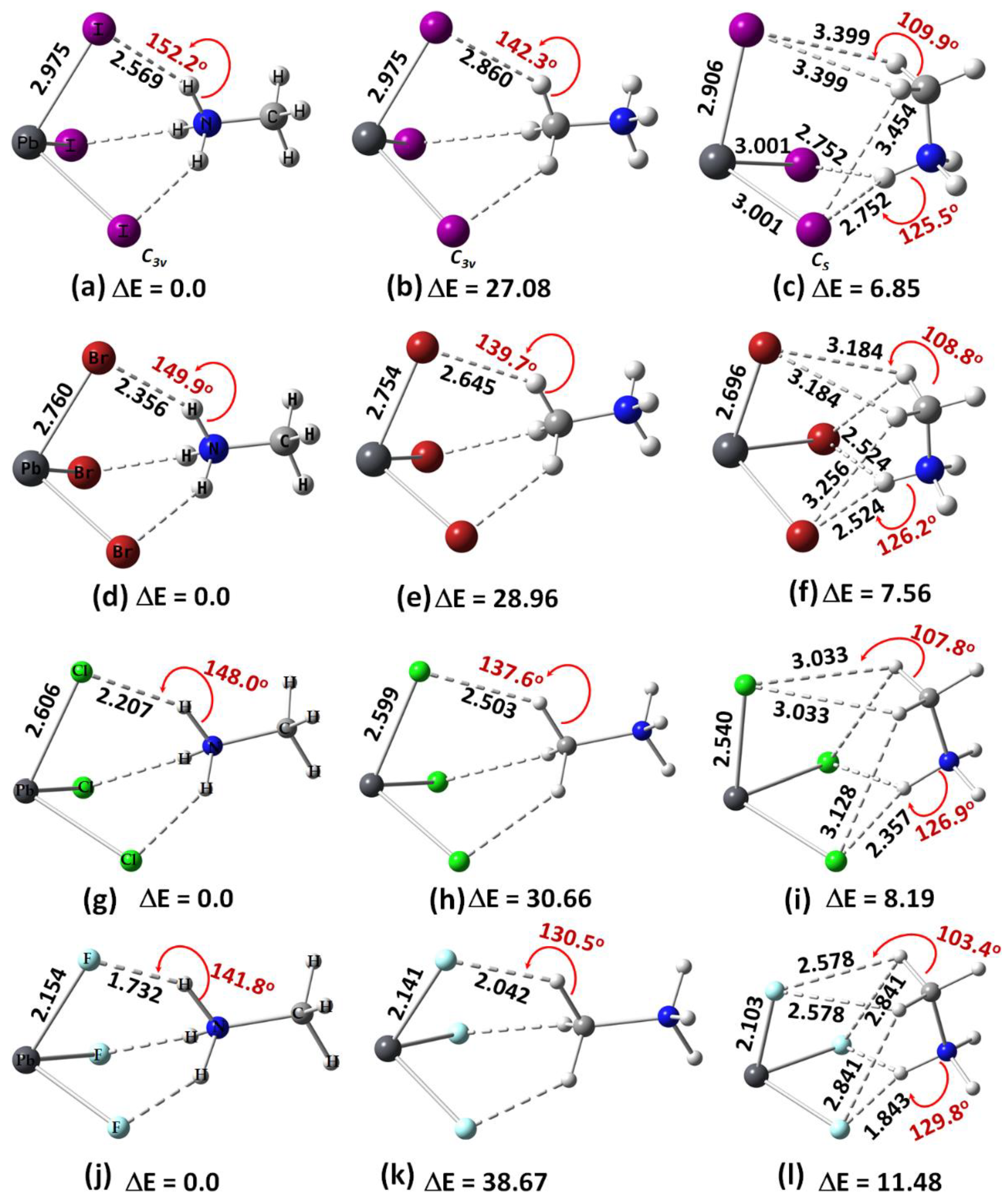
2.1. Methylammonium Tetrel Halide Perovskite Ion Pairs

The (111) direction of the organic cation in the crystalline cubic structure of MAPbI3 results when the ammonium end of the cation faces a triangular face (formed by three iodides) of a [TtI64−] octahedron of an extended solid (Figure 1a). When the unit cell shown in Figure 1a (left) is expanded, the methyl end of the diagonally placed MA faces the triiodide face of a [TtI64−] that occupies the opposite corner of the cube (Figure 1a (right)); this also represents the (111) direction of the organic cation. The resulting structure when the organic cation is oriented along the (011) direction is shown in Figure 1b (right). A very similar orientation of the organic cation is likely to be obtained when X = Br (or Cl).
The orientation of the organic cation in cubic MAPbI3 plays a fundamental role in determining the material optoelectronic properties of methylammonium tetrel halide perovskites [25]. For instance, when MA orientates along the (011) direction (Figure 1b), the inorganic octahedral cage distorts and the bandgap of cubic MAPbI3 becomes indirect; when the organic cation is oriented along the (111) direction, there is no distortion of the inorganic octahedral cage with the PbI64− units linearly bonded to each other through the octahedral edges, and the material has a direct bandgap. Using the results of periodic DFT calculations [25], it was shown that the relaxation of the halide perovskite lattice with the molecular cation as shown in Figure 1a (left) does not distort its orientation in any crystallographic direction. This was not the case when MA initially orientated in the (001) direction; the relaxation of the lattice produced a structure with MA orientated along the (011) or an equivalent direction. Both configurations were local minima, with an energy difference of 20 meV in favor of the lattice that has the organic cation along the (011) direction [25].
A question that arises is whether the orientations of MA observed in the high-temperature phase of the system also occur in the gas phase when there are no boundary conditions. To address this question, we examined the geometries of [CH3NH3+•PbI3] ion pairs in the gas phase (Figure 2a–c). The first two panels, Figure 2a,b, show that the ammonium and methyl ends of MA face the triangular iodide face of the anion, respectively, and they mimic the (111) orientation of the cation in the periodic structure (Figure 1a). The third configuration of [CH3NH3+•PbI3] (Figure 2c) resembles the (011) orientation of MA in the solid state (Figure 1b). The corresponding conformations were also identified for [CH3NH3+•PbBr3] (Figure 2d–f), [CH3NH3+•PbCl3] (Figure 2g–i) and [CH3NH3+•PbF3] (Figure 2j–l). We will refer to the first two conformations of each ion pair type on the left of each panel, which mimic the (111) direction of the organic cation, as Conf. 1 and 2, respectively; the conformation on the right of each panel, which mimics the (011) orientation of the cation, will be referred to as Conf. 3. In each case, it was found that Conf. 1 is more stable than Conf. 2 or Conf. 3 (relative values of ΔE are shown in Figure 2), i.e., Conf. 1 > Conf. 3 > Conf. 2. Conf. 1 is calculated to be the only minimum, while Conf. 2 and 3 are, respectively, second- and first-order transition state gas phase structures.
The orientation of the organic cation inside the inorganic cage (Figure 1a, right) determines the nature of the charge-assisted hydrogen bonding between it and the cage. When it lies along the (111) orientation, the three H atoms of the ammonium end (or the methyl end) of MA are involved in three equivalent N–H···I (or C–H···I) hydrogen bonds with the three I atoms of the I3 of [PbI3]; see for example, Figure 2a,b, for [I3Pb···NH3CH3] (Conf. 1) and [I3Pb···CH3NH3] (Conf. 2), respectively. When the cation is oriented along the (011) direction, the N–H···I/C–H···I hydrogen bonds of MA with the [PbI3] face are not equivalent; the two C–H···I (equivalent) hydrogen bonds are longer than the N–H···I hydrogen bonds (see, for example, Conf. 3 ([I3Pb···H3NCH3]), Figure 2c). The same trend was found when X = Br, Cl and F (see Figure 2d–f, g–i and j–l, respectively).
For a given halogen derivative in [CH3NH3+•PbX3], the N–H···X hydrogen bond distances are shorter than the C–H···X hydrogen bonds, in agreement with what was observed in the solid state for CH3NH3PbX3 (X = Cl, Br, I) perovskites [22,23]. This means that the charge-assisted N–H···X hydrogen bonds formed by the ammonium end of MA are stronger than the C–H···X hydrogen bonds formed by the methyl end of MA, and their strength increases with the electronegativity of the halogen (F > Cl > Br > I). For both Conf. 1 and Conf. 2, the hydrogen bond distance decreases as the halogen becomes more electron-withdrawing (see Figure 2a,d,g,j or Figure 2b,e,h,k), a feature found for ion pairs when Tt = Sn and Ge, but not when Tt = Si (see Figures S1–S4 of the Electronic Supplementary Information, ESI). In all cases, the hydrogen bonds are non-linear (∠N–H···X or ∠C–H···X < 143°), regardless of their type, and (based on the bond lengths) the strength of the Pb–X coordinate bonds decreases passing from F through Br to Cl to I in [CH3NH3+•PbX3] (see Figure 2a,d,g,h, for example).
Replacement of Pb by Sn and Ge in [CH3NH3+•PbX3] did not appreciably change the nature of the coordination between Tt and X in TtX3, although the hydrogen-bonded environment was affected (see Figures S1a–l and S2a–l of the ESI). When Tt = Si in [CH3NH3+•TtX3], Conf. 3 was found to be unstable for X = I and Br (see Figure S3a–d), but [X3Si···NH3CH3] was more stable than [X3Si···CH3NH3]. Figures S3e–g and S4a-c of the ESI provide the geometric and relative energy details of the ion pair series [CH3NH3+•SiX3] and [CH3NH3+•SiF3], respectively. In all cases, Conf. 1 was observed to be more stable than Conf. 2 and Conf. 3.
Conf. 3 was obtained from the initial geometry shown in Figure S4d for each of the three tetrel halide perovskite ion pair series, [CH3NH3+•PbX3] (X = Cl, Br, I). However, when this initial configuration was used for relaxation of the [CH3NH3+•SiF3] ion pair, the resulting geometry was no longer an ion pair and the initial configuration was not retained after energy minimization. This was not the case when the methyl and ammonium ends of the organic cation were pointed toward the center of the trifluoride triangular face of SiF3. The energy-minimized geometry in Figure S4d shows that there is a significant interaction between the two ionic moieties when in close proximity, with a breaking of the N–H covalent bond and the formation of two neutral species, SiHF3 and CH3NH2, due to complete hydrogen transfer from the ammonium end to the anion. (This is addressed later.) Due to this, we then used the optimized geometry of the [PbF3···NH3CH3+] ion pair (Figure 2l) as an initial configuration, replacing Pb with Si; the final energy-minimized geometry is shown in Figure S4c. Although this was the case for the system with the anion SiF3, a similar attempt did not stabilize the analogous geometry of the ion pair when X = I and Br.
To help determine the validity of these conclusions we performed an MESP analysis; the results are summarized in Table 1. Analysis of these data suggests that the Si surfaces of [SiX3···NH3CH3+] (X = I and Br) ion pairs are weakly positive but are negative in the remaining eight ion pairs of the same series regardless of the identity of the halogen derivative. The halogen in [SiX3] has high electron density compared to the surface of the Si atom. There are three equivalent negative σ-holes on Si in each of the two ion pairs for a given halogen except for Conf. 3, and their strength decreases with an increase in the size of the halogen in [SiX3]. The σ-hole on Si is more electrophilic when the ammonium head faces the triangular X3 face of [SiX3] than when the methyl head faces that face. This is reasonable since the –NH3 group in MA is strongly electrophilic and hence relatively more electron-withdrawing than the methyl head. The first arrangement causes the development of a structure with relatively greater depletion of charge density on the surface of the Si atom along the outermost extensions of the three X–Si bonds. Since the lone pair of the Si lies along the outer extension of the C3v axis, the VS,min associated with it is increasingly more positive as the halogen becomes more electron-withdrawing, making the entire surface of the Si atom nucleophilic.
The electrostatic surfaces of Pb in [PbX3···NH3CH3+], [PbX3···CH3NH3+] and [PbX3···H3NCH3+] have electron-deficient regions along the X–Pb bond extensions (VS,max (X–Pb) > 0) (Figure 3). They are equivalent in Conf. 1 or 2 but not in Conf. 3. The surface of Pb along the outermost extension of the C3v axis is also positive, represented by a positive local minimum of potential (VS,min (Pb) > 0). For example, values of VS,min (Pb) are 22.2, 9.6 and 18.3 kcal mol−1 for Conf. 1, Conf. 2 and Conf. 3, as shown in Figure 3a–c (bottom), respectively. These results indicate that the coordinately bonded Pb atom has three electrophilic σ-holes in these molecular ion pairs, and its surface is entirely electrophilic. An exception was found for [F3Pb···CH3NH3+] when the 0.001 a.u. isoelectronic density envelope was invoked on which to compute the potential (VS,max (F–Pb) = −0.4 kcal mol−1), but a larger isoelectronic density envelope of 0.0015 a.u. gave VS,max (F–Pb) = 4.1 kcal mol−1. Both C and N atoms along the N–C and C–N bond extensions have electrophilic σ-holes in Conf. 1 and Conf. 2, respectively, and their strength in the former was weaker than that in the latter (VS,max(N–C) and VS,max(C–N) 38.2 and 90.4 kcal mol−1, respectively). Similarly, the lateral portions of the halogen in Conf. 1 or Conf. 2 are equipotential, described by VS,min (X) < 0, although this was not the case in Conf. 3 because of symmetry. For instance, the surface of the halogen that is hydrogen-bonded to the methyl group is less negative than the halogens bonded to the ammonium group in Conf. 3 (VS,min (X) −23.1 and −17.4 kcal mol−1, respectively). The detailed nature of the MESP graphs of the three conformations of [CH3NH3+•SnI3] and [CH3NH3+•GeI3] ion pairs are shown in Figures S5 and S6 of the ESI, respectively.
As observed in the case of methylammonium lead halide perovskite ion pairs, the tin surfaces of the three tin-based halide perovskite ion pairs (I3Sn···NH3CH3, I3Sn···H3NCH3 and Br3Sn···NH3CH3) are entirely positive, while the surfaces of the same atom in the remaining nine tin halide perovskite ion pairs are not completely positive; VS,min (Sn) is negative in the first two and negative in the latter nine ion pairs (Table 1). Except for F3Sn···CH3NH3, the three σ-holes on the surface of Sn along the X–Sn bond extensions are electrophilic (VS,max(X–Sn) > 0). They are negative for F3Sn···CH3NH3 regardless of the isoelectronic density envelopes used for mapping of the potential (cf. Table 1).
In the case of germanium halide perovskite ion pairs, VS,min(Ge) is found to be negative for all 12 ion pairs, evidence that the lone pair of Ge is active along the outer extension of the C3v axis. The σ-holes on the surface of Ge in I3Ge···CH3NH3 (X = I, Br, Cl) are not all nucleophilic, although they are for the germanium fluoride perovskite ion pairs (F3Ge···NH3CH, F3Ge···CH3NH3 and F3Ge···H3NCH3). This suggests that the formation of an MAGeF3 perovskite is unlikely in the solid state, as inferred for the MASiX3 systems (vide supra). The synthesis of the chloro- and bromo-analogues of MAGeF3 may be feasible, although the interaction between the ion pairs will be weaker and thus it is expected that the solid-state compounds would be readily degraded.
Among the ion pairs investigated, the lead atom in Br3Pb···NH3CH3 provides the strongest σ-holes, suggesting that they are likely to form stronger oligomers, or clusters, when a number of such ion pairs are in close proximity. The phenomenon is likely to persist in the crystalline phase and rationalizes why MAPbBr3 perovskites were observed to be significantly more stable under ambient conditions than MAPbI3 perovskite materials [59,101,102]. A number of suggestions have been provided to explain the enhanced stability of MAPbBr3 compared to MAPbI3, including bromide migration, and the reduced activation energy, diffusion coefficient and concentration for halide ions in MAPbBr3 compared to MAPbI3 [59].

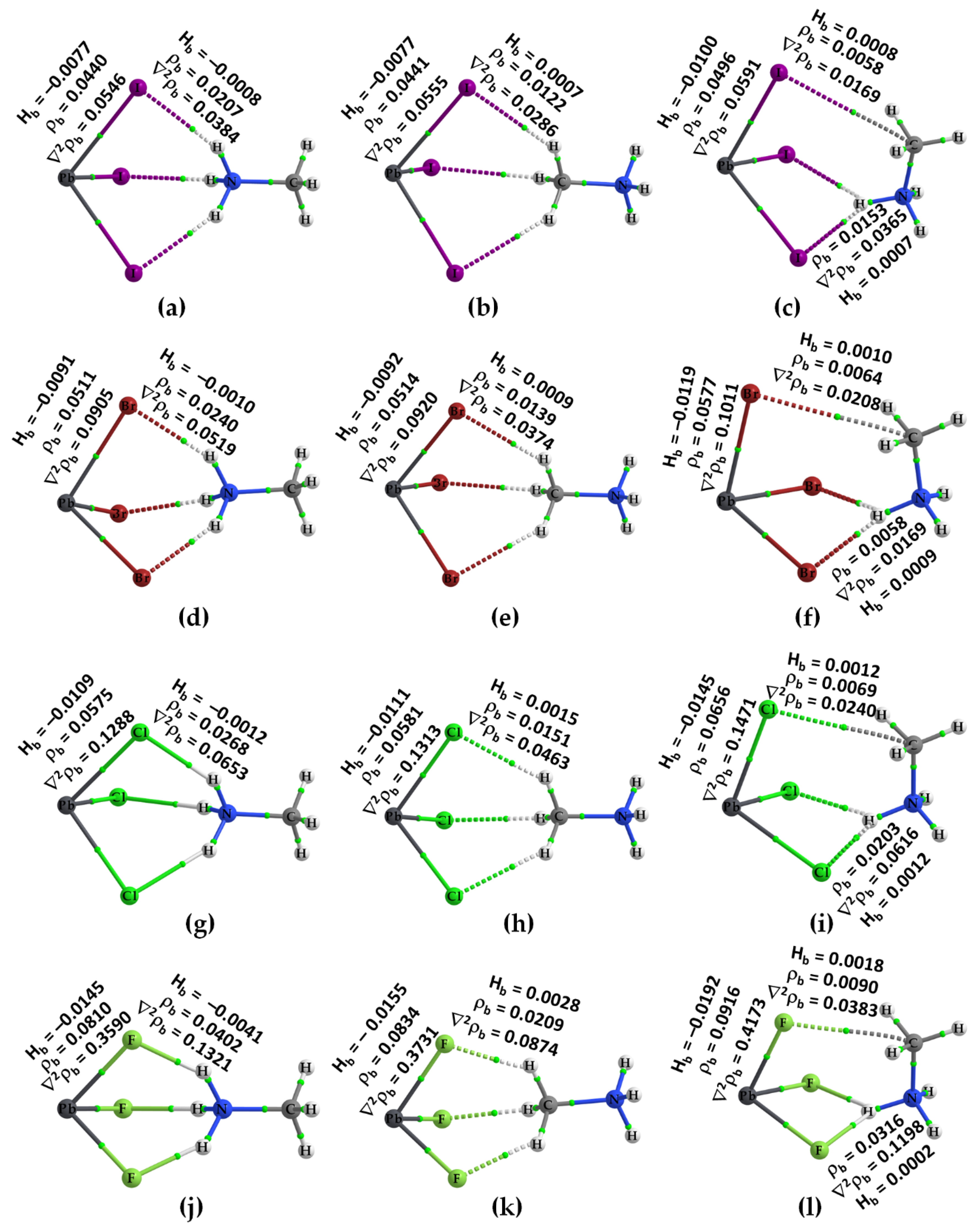
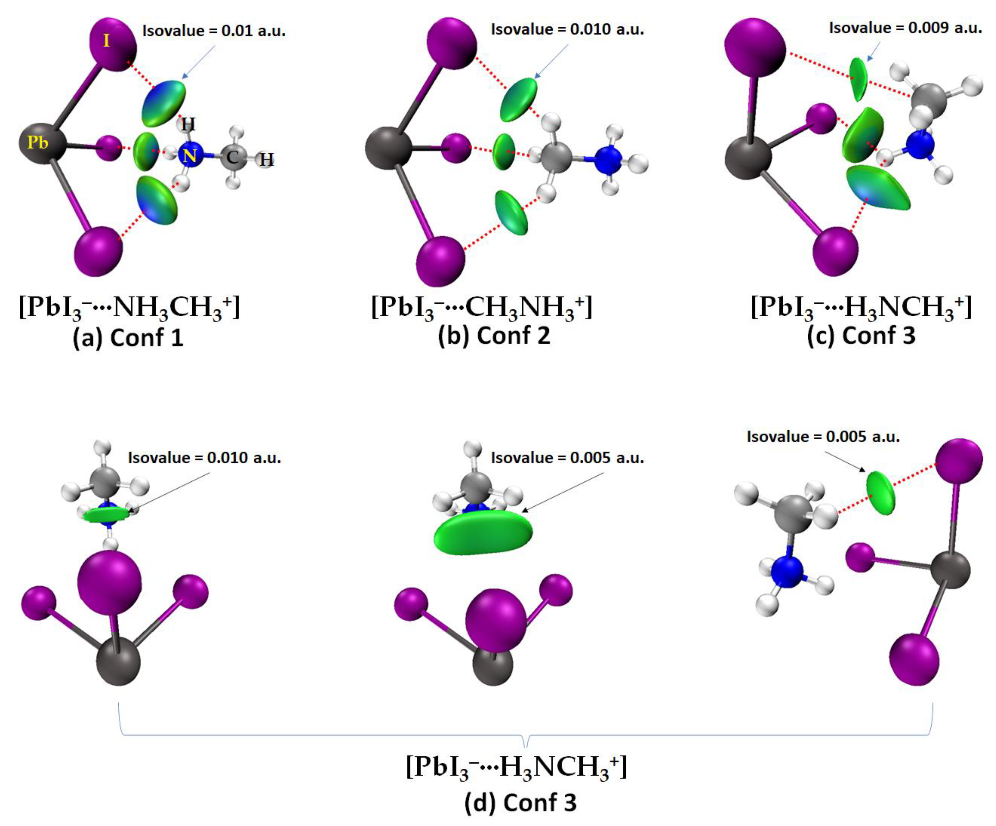
2.2. QTAIM, IGM-δginter and NBO Analysis of Ion Pairs

The molecular graphs of all twelve ion pairs associated with the three conformers [PbX3···NH3CH3+], [PbX3···CH3NH3+] and [PbX3···H3NCH3+] (X = I, Br, Cl, F) are shown in Figure 4. The N–H···X hydrogen bonds in Conf. 1 and Conf. 3 are shown in the ion pairs (Figure 4a,c,d,f,g,i,j,l) as dotted bond paths between the bonded atomic basins with a (3, –1) bond critical point (bcp) between them [78]. The C–H···X hydrogen bonds are present in Conf. 2 in which the methyl H atoms point towards the triangular X3 face of the inorganic anion. They are weaker than the N–H···X hydrogen bonds, indicated by the charge density values, ρb, at their corresponding bcps.
QTAIM misses the bond path topologies of the C–H···X hydrogen bonds in the molecular graphs shown in Figure 4c,f,i,l; this is not unexpected since the intermolecular distances associated with these weakly bonded close contacts (cf. Figure 2c,f,i,l) are longer than the sum of the van der Waals radii of X and H (rvdW(H) = 1.20 Å; rvdW(F) = 1.46 Å; rvdW(Cl) = 1.82 Å; rvdW(Br) = 1.86 Å; rvdW(I) = 2.04 Å) [103]. Very similar results have been reported recently in a study that focused on the physical chemistry of anion–molecule systems driven by tetrel bonds [82]. QTAIM identifies a C···X tetrel bond between the methyl C of MA and an X site on PbX3 in Conf. 3 (cf. Figure 4c,f,i,l), instead of C–H···X hydrogen bonds; the emergence of such an interaction is not surprising since the outer electrostatic surface of the C atom along the H–C bond extensions is positive.
The topological charge density characteristics of the intermolecular interactions identified by QTAIM are different from those of the Pb–X coordinate bonds. Most of the former, but not all, are characterized by ∇2ρb > 0 and Hb > 0, whereas the latter are characterized by ∇2ρb > 0 but Hb < 0 and a relatively large ρb, where ∇2ρb and Hb are the Laplacian of the charge density and the total energy density, respectively. These results suggest that most of the intermolecular (interionic) interactions are of the closed-shell type [104], whereas the coordinate bonds in the ion pairs are of mixed character [105]. For each series with a given halogen derivative, the value of ρb is the largest for the N–H···X hydrogen bond (see Conf. 1 and Conf. 3) and the smallest for the C···X tetrel bond (Conf. 3). The largest value of ρb is associated with the N–H···X hydrogen bonds in some ion pairs, for which the bond paths between the interacting ions are described by solid lines in atom colors (viz. [Cl3Pb···NH3CH3] (Figure 4g) and F3Pb···NH3CH3] (Figure 4j)). The three equivalent N–H···X hydrogen bonds in Conf. 1 of each series possess some covalency character since Hb < 0 at the bcps [105] (see Figure 4a,d,g,j).
That QTAIM missed the C–H···X hydrogen bonds in Conf. 3 is confirmed by our IGM-δginter analysis, presented in Figure 5. The results demonstrate that the IGM-δginter isosurface volumes (circular or flat), colored bluish green (or green), spread within the area between the interacting atomic basins that are non-covalently engaged with each other, a color code that appears only when there is an attractive interaction between the interacting basins. These isosurfaces are representatives of ρ × sign (λ2) < 0, where λ2 is the second eigenvalue of the Hessian of the charge density matrix. When ρ × sign (λ2) > 0, one would expect repulsion between interacting basins, and these are generally described by red isosurfaces. Van der Waals interactions correspond to ρ × sign (λ2) ≈ 0 [93,94]. Clearly, as inferred from geometries alone (see Figure 2, for example), Conf. 1 and Conf. 2 are stabilized by N–H···I and C–H···I hydrogen bonds, respectively, with the former relatively stronger than the latter. Similarly, Conf. 3 is stabilized by N–H···I, C···I and C–H···I close contacts. The latter are very weak and appear only when an isovalue < 0.01 a.u. is used. The flat capsule type isosurface volume between the methyl group in MA and I in the inorganic anion in Figure 5d suggests that the attraction between the interacting units is weakly dispersive and includes weak C–H···I hydrogen bonds and the C···I tetrel bond. The presence of the former was confirmed when the interacting atomic basins (H and I) in the ion pair were used in the analysis of IGM-δginter for which a smaller isovalue of 0.005 a.u. was invoked. This is shown in Figure 5d (right), and the IGM-δginter isosurface volume between I and H representing C–H···I is more localized and weaker. These conclusions may hold for ion pairs formed with any other halogen derivative.
We carried out a second-order natural bond orbital analysis [106,107] to provide some insight into the nature of the charge transfer (hyperconjugative) interactions that occur between the “filled” (donor) Lewis-type NBOs and “empty” (acceptor) non-Lewis NBOs, but only for the three confirmations of [CH3NH3+•PbI3] (Figure 5). The results suggest that the charge transfer interactions between the acceptor and donor NBOs responsible for either of the two N–H···I hydrogen bonds in Conf. 3 ([PbI3···H3NCH3+]) can be described by n(3)I → σ*(N–H) (E(2) = 6.71 kcal mol−1) and σ(Pb–I) → σ*(N–H) (E(2) = 2.0 kcal mol−1), whereas the C–H···I hydrogen bond and H–C···I tetrel bond are described by n(3)I → σ*(N–C) (E(2) = 0.17 kcal mol−1) and n(3)I → σ*(N–C) (E(2) = 0.16 kcal mol−1), respectively, where n(3) refers the third lone pair and E(2) is the second-order stabilization energy [106,108]. The charge transfer interaction for each of the three N–H···I hydrogen bonds in Conf. 1 ([PbI3···NH3CH3+]) is described by n(3)I → σ*(N–H) (E(2) = 14.52 kcal mol−1), σ(Pb–I) → σ*(N–H) (E(2) = 0.52 kcal mol−1) and n(3)I → σ*(N–C) (E(2) = 0.36 kcal mol−1), with the latter indicative of a weak C–N···I pnictogen bond. Similarly, the charge transfer interaction associated with each of the three C–H···I hydrogen bonds in Conf. 2 [PbI3···CH3NH3+] is described by n(3)I → σ*(C–H) (E(2) = 4.17 kcal mol−1), and n(3)I → σ*(C–N) (E(2) = 0.47 kcal mol−1), indicating that the σ* anti-bonding orbital of the C–N bond of the organic cation has the ability to act as an acceptor of electronic charge density via a charge transfer interaction with the π-type lone pair orbital of iodine in the inorganic anion and corresponds to an I–C···I tetrel bond. Since the geometric topology is very similar for all ion pairs investigated, it may be assumed that similar charge transfer interactions occur between the interacting ions that lead to the formation of the other ion pairs investigated.

2.3. Energy Stability of the Ion Pairs
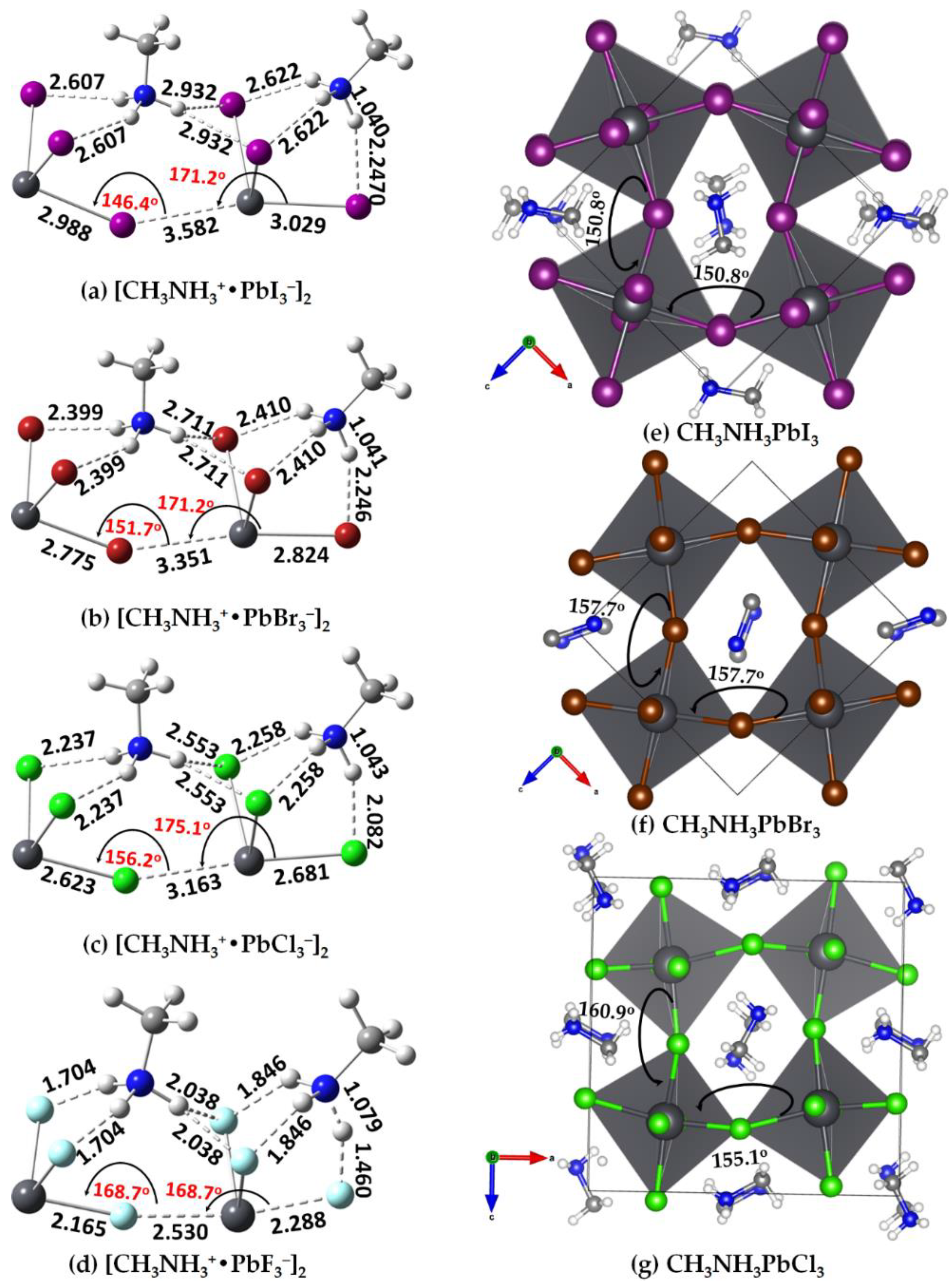
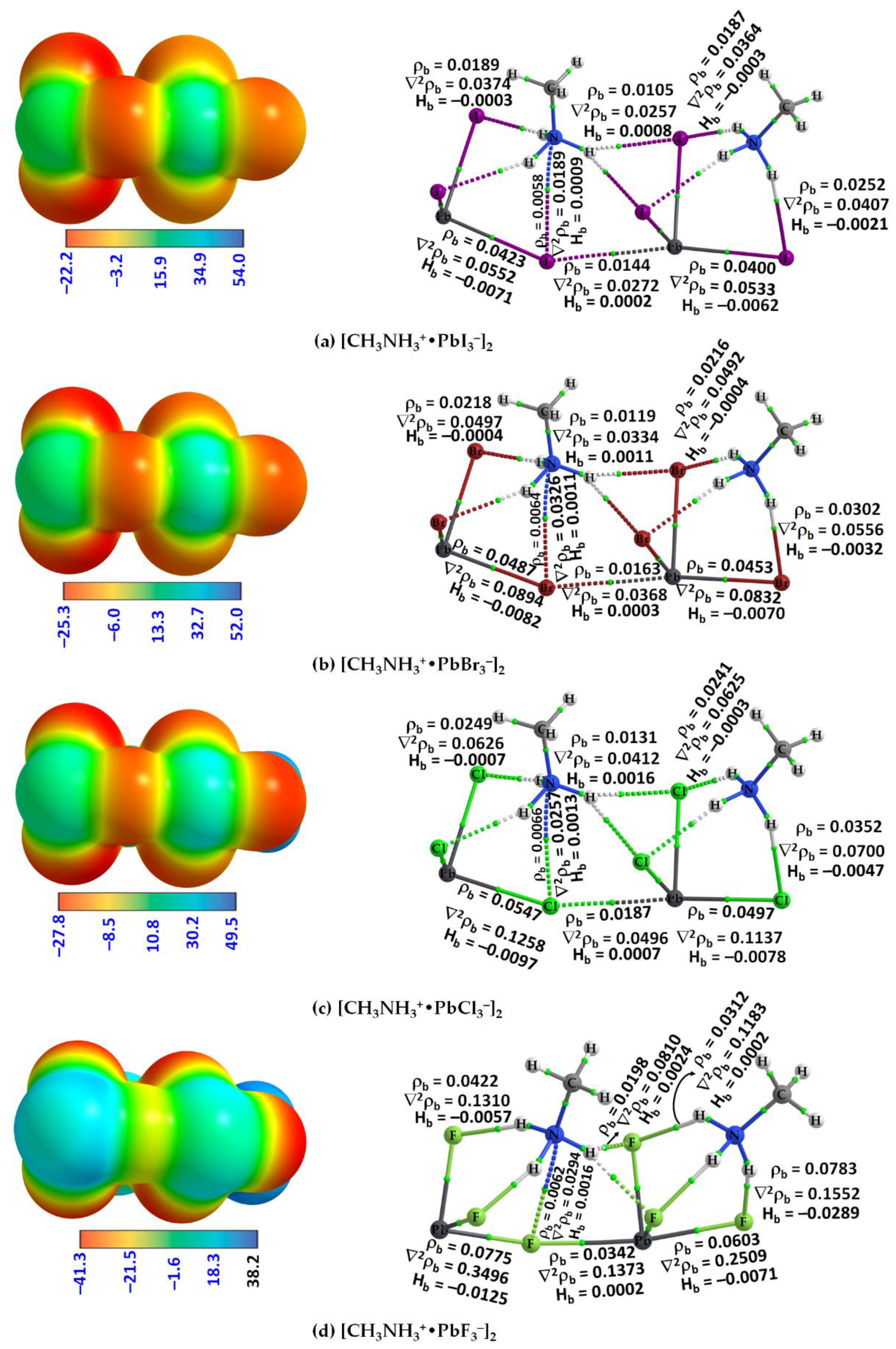
The interaction energies ΔE of all the ion pairs investigated are summarized in Table 2; the total electronic energies obtained from the geometries of the ion pairs and the individual ions in the energy-minimized geometries of the same ion pairs were used. The counterpoise procedure of Boys and Bernardi [109] was followed, as implemented in Gaussian 16 [110] (see Section 4 for details). Among the three conformers examined for each tetrel derivative for a given halide, the hydrogen-bonded ion pair that has the ammonium head pointing towards the X3 triangular face of the anion was found to be the most stable. For example, the relative stability of the three conformers of [CH3NH3+•PbI3] follows the order: Conf. 1 (I3Pb···NH3CH3) > Conf. 3 (I3Pb···H3NCH3) > Conf. 2 (I3Pb···CH3NH3) (Figure 2a–c), which is similar to that of their corresponding interaction energies, summarized in Table 1. The most stable ion pair was F3Pb···NH3CH3, with an interaction energy of −138.54 kcal mol−1 (Table 2).
The interaction energy listed in Table 2 for each ion pair is not the consequence of a single hydrogen bond. For example, this means that the ΔE(BSSE) of −104.85 kcal mol−1 for I3Pb···NH3CH3 arises from three equivalent charge-assisted I···H(N) hydrogen bonds; that of −76.33 kcal mol−1 for I3Pb···CH3NH3 is due to three equivalent charge-assisted I···H(C) hydrogen bonds; and that of −97.53 mol−1 for I3Pb···H3NCH3 is the result of a pair of equivalent charge-assisted I···H(N) hydrogen bonds and a pair of charge-assisted I···H(C) hydrogen bonds.
For ion pairs formed with a given tetrel derivative and a variable halide, i.e., [X3Pb···NH3CH3] where X = F, Cl, Br, I, the interaction energy increases (F > Cl > Br > I) as the polarizability of the halide decreases (I > Br > Cl > F). This is intuitively obvious since the electronegativity of the halides plays a significant role in determining the strength of an intermolecular charge-assisted hydrogen bonds.
While the interaction energies of the fluorinated ion pairs (viz. F3Pb···H3NCH3 and F3Sn···H3NCH3) are very large, and are of the ultra-strong type, these ion pairs hinder the formation of their corresponding perovskite structures in the solid state since the volume of the cage formed by the inorganic moiety is unlikely to be large enough to accommodate the organic cation.
On the other hand, the interaction between the two neutral molecules SiHF3 and CH3NH2 in F3HSi···NH2CH3 (Figure S4d) is not weak. The monomers in the complex are bonded to each other through a Si···N tetrel bond. The formation of this bond is perhaps obvious since the lone pair on the ammonium N is directly engaged with the positive σ-hole on the Si atom in SiHF3, which appears along the F–Si bond extension. The uncorrected (and BSSE-corrected) interaction energy of this bond is –22.80 (–22.23) kcal mol−1, indicative of a reasonably strong non-covalent interaction [81].

2.4. [CH3NH3+•TtX3]2 (Tt = Si, Ge, Sn, Pb; X = F, Cl, Br, I) Dimers

The fully relaxed geometries of [CH3NH3+•PbI3]2 (X = F, Cl, Br,I) dimers are shown in Figure 6. The connectivity between the ion pairs is driven by three types of intermolecular interactions: the N–H···X hydrogen bonds, the C–N···X pnictogen bonds and the X–Pb···X tetrel bonds. A tetrel bond occurs when there is evidence of a net attractive interaction between an electrophilic region associated with a covalently or coordinately bonded tetrel atom (or atoms) in a molecular entity and a nucleophilic region in another, or the same, molecular entity [81]. The same underlying definition applies to a pnictogen bond, with the terms “tetrel bond” and “tetrel atom” replaced by the terms “pnictogen bond” and “tetrel atom”, respectively. Both the pnictogen and tetrel bonds are linked, with a bent ∠Pb–X···Pb angle between the two ion pairs forming the [CH3NH3+•PbI3]2 dimer. Although these were obtained from gas phase calculations, a very similar geometric feature was found in the low-temperature orthorhombic structure of the CH3NH3PbX3 perovskites (X = Cl, Br) (Figure 6e–g); however, the X–Pb bonds in the latter are nearly equivalent as a result of crystal packing forces.
A question that arises is why the [PbI3] anions are bonded to each other in the crystal, forming an infinite array of [PbX64−] octahedra that form cage-like structures to host the organic cations, even though the anions are expected to coulombically repel each other. An immediate answer to this is probably the presence of CH3NH3+ that locally polarizes the potential on the electrostatic surface of the tetrel atom in [PbI3] when in close proximity, driven by an extensive number of double-charge-assisted N–H···X and C–H···X hydrogen bonds that appear between them. As the surface of the tetrel atom in the ion pair [CH3NH3+•TtX3] is highly electrophilic, featuring three positive σ-holes on Tt (Tt = Pb and Sn), it is capable of accepting electrons simultaneously from three halogens of three interacting ion pairs [CH3NH3+•TtI3] at equilibrium, forming the [TtX64−] octahedra in the crystalline phase. QTAIM calculations suggest there is an appreciable transfer of charge between the organic and inorganic ions, facilitating the formation of the ion pair, and this is true in all three conformations investigated for [CH3NH3+•TtX3], a feature that also occurs between the ion pairs responsible for the dimers. When the same process of assembly continues with [CH3NH3+•PbX3] ion pairs, the formation of CH3NH3TtX3 perovskite in the solid state is the likely consequence, a result of interplay between the σ-hole-centered tetrel bonds and other non-covalent interactions. The MESP plots that provide evidence of the formation of X–Tt···X tetrel bonds (dotted lines) between two ion pairs, leading to the formation of [CH3NH3+•PbX3]2 dimers, are shown in Figure 7a–d (left). They show that the positive σ-hole on Pb in an ion pair is in coulombic attraction with the negative halide of the anion with which it interacts.
As shown in Figure 6a–d, the organic cation in the [CH3NH3+•PbX3] ion pair on the left connects with another ion pair on the right through N–H···X hydrogen bonds and X–Tt···X tetrel bonds. The former are equivalent in a given ion pair, and become shorter as the size of the halogen decreases from I through to F. Based on the bond distances, it is clear that the hydrogen bonds are stronger in [CH3NH3+•PbF3] and weaker in [CH3NH3+•PbI3]. This might be expected since the lighter halogens are more electronegative and hence able to form stronger hydrogen bonds. Partial halogen transfer from [PbF3] on the right ion pair [CH3NH3+•PbF3] towards the ammonium H atom is evident in the [CH3NH3+•PbF3]2 dimer (Figure 6d); this may indicate that the formation of the perovskite CH3NH3PbF3 is unlikely in the solid state. The result also suggests that the formation of a different type of ion pair, methylammonium fluoride ([CH3NH3+•F]), is a likely consequence when more than two units of the [CH3NH3+•PbF3] ion pair are in close proximity. The geometric arrangement between them would hinder the formation CH3NH3PbF3 perovskite in the crystalline phase and might explain why CH3NH3PbF3 is unknown in the solid state.
The X–Tt···X tetrel bonds formed between the ion pairs in the dimers at equilibrium are all less than the sum of the van der Waals (vdW) radii of Tt and X; for instance, the tetrel bond distances of 3.582, 3.351, 3.163 and 2.530 Å in [CH3NH3+•PbI3]2 (Figure 6a), [CH3NH3+•PbBr3]2 (Figure 6b), [CH3NH3+•TPbCl3]2 (Figure 6c) and [CH3NH3+•PbF3]2 (Figure 6d) are much less than the vdW radii sum 4.64 (Pb + I), 4.46 (Pb + Br), 4.42 (Pb + Cl) and 3.50 Å (Pb + F) [104], respectively. Moreover, they are quasi-linear, (∠X–Pb···X values between 168° and 176°). This signature satisfies characteristic features d and f and Note 4 of tetrel bonds discussed in a recently suggested definition of a tetrel bond [81].
The geometries of the isolated ion pair, [CH3NH3+•TtX3], and its dimer, [CH3NH3+•TtX3]2, and the intermolecular interactions in them are not identical. A major rearrangement of the monomers occurred on dimer formation. In particular, the organic cation shared between the two inorganic anions rearranged in a manner so as to maximize its non-covalent interactions with the halides of the two inorganic moieties (Figure 6), while the organic cation on the right retains its shape as observed in the isolated ion pair itself (cf. Figure 2). The physical arrangement between the ions in the former (left) part of the dimer resembles the geometry of crystalline tetrel halide perovskites (Figure 6e–g) in the low-temperature orthorhombic phase. The corner-shared [TtX64−] octahedra in these structures are tilted along the crystallographic ac-axes. The tilting can be gauged from the ∠Pb–X···Pb angle between a pair of octahedra that are located at corners of a significantly distorted cube.
The tilt angle is smallest in the [CH3NH3+•PbI3]2 dimer (∠Pb–I···Pb = 146.4°) and increases as the size of the halogen in [CH3NH3+•PbX3]2 decreases from Br through Cl to F (∠Pb–Br···Pb = 151.7°; ∠Pb–Cl···Pb = 156.2°; ∠Pb–F···Pb = 168.7°). Although this angle is obtained from a linearly arranged structure in the gas phase, it reflects the same feature observed in the crystalline phase. For instance, the Cl–Pb–Cl angles are 155.1°, 160.9° and 163.9° in the low-temperature (100 K) orthorhombic (o) phase of MAPbCl3 [111] (ICSD ref: 241415) along the crystallographic a-, b- and c-directions, respectively (two are shown in Figure 6g). In the case of (120 K) o-MAPbBr3 [112] (ICSD ref: 268782), the corresponding angles are 157.7°, 169.6° and 157.7°, respectively (two are shown in Figure 6f). In the Pnma structure of (100 K) o-MAPbI3 [113] (ICSD ref: 428898), the tilt of the octahedra is such that the Pb–I–Pb angles (Figure 6e) are Pb–I–Pb = 161.94(16)° (along b-axis) and Pb–I–Pb = 150.75(12)° (along the a- and c-axes) respectively. The average tilt angle, ∠Pb–X–Pb, in o-MAPbCl3, o-MAPbBr3 and o-MAPbI3 is 160.0°, 161.4° and 154.5°, respectively, in reasonable agreement with the tilt angles of the gas phase dimers. Geometric details of [CH3NH3+•TtX3]2 (Tt = Sn, Ge, Si; X = F, Cl, Br, I) dimers are given in Figures S7 and S8 of the ESI.
It has been shown that to improve the efficiency of perovskite solar cells, it is necessary to tune the degree of octahedral tilting of the halide framework, which affects the optical band gap and the effective mass of the charge carriers [75,114]. The steric effects dominate the magnitude of the tilt in inorganic halides, while hydrogen bonding between the organic cation and the halide frame plays an important role in hybrids, and tuning the degree of hydrogen bonding can be used as an additional control parameter to optimize the photoelectric conversion properties of the perovskites [75]. In the absence of hydrogen bonding, the octahedra in the tetrel halide perovskites do not tilt at all, a view which is in disagreement with our results discussed above and elsewhere [22]. In the case of all-inorganic alkali tetrel halide perovskites, the in-phase tilting provides a better arrangement of the larger bromide and iodide anions, which minimizes the electrostatic interactions, improves the bond valence of the A-site cations and enhances the covalency between the A-site metal and Br or I ions [115].
The chemical bonding shown in the left portion of the [CH3NH3+•PbX3]2 dimer (Figure 6a–c), which includes N–H···X hydrogen bonds, a C–N···X pnictogen bond and an X–Pb···X tetrel bond, is very similar to that found in crystals of tetrel halide perovskites. A major difference between them is that the gas phase structures do not have hydrogen bonds formed by the methyl group of the organic cation; these can evolve if the [CH3NH3+•PbX3]2 dimer is surrounded with additional ion pairs in all three directions. Likewise, the C–N···X pnictogen bond apparent in the left portion is absent on the right of the [CH3NH3+•PbX3]2 dimer. An extended array of [CH3NH3+•PbX3] ion pairs to the right of the dimer will enable the terminal organic cation to rearrange in a manner as on the left so the terminal hydrogen H atom of the ammonium group of the organic cation on the right can engage in the formation of N–H···X bonding interactions with the halogen atoms of a third ion pair; the N site of the same cation can also engage with the tetrel-bonded X site to form a C–N···X pnictogen bond. These intermolecular interactions were confirmed by a QTAIM analysis, see Figure 7 (right). The analysis shows that there is variability in the character of the N–H···X hydrogen bonding interactions in the gas phase geometries, characterized by the topological properties of the charge density.
The QTAIM results suggest that the strength of the C–N···X pnictogen bond increases with an increase in the size of the halogen in [CH3NH3+•TtX3]2. For instance, ρb (∇2ρb) [Hb] values at the N···X bcps were 0.0070 (0.0231) [0.0010], 0.0080 (0.0293) [0.0012], 0.0086 (0.0339) [0.0015] and 0.0094 (0.0463) [0.0023] a.u. for [CH3NH3+•SnI3]2, [CH3NH3+•SnBr3]2, [CH3NH3+•SnCl3]2 and [CH3NH3+•SnF3]2, respectively. The positive sign of both ∇2ρb and Hb indicates that the pnictogen bond is of the closed-shell type, and its magnitude signifies that the close contact is more ionic in nature in [CH3NH3+•SnF3]2 than in [CH3NH3+•SnI3]2. The trend in the charge density properties is in agreement with the geometric features of the pnictogen bond, viz. bond distance r(N···X) (and bond angle (∠C–N···X)): 3.634 (174.3°), 3.406 (172.1°), 3.261 (170.2°) and 2.870 Å (172.6°) in [CH3NH3+•SnI3]2, [CH3NH3+•SnBr3]2, [CH3NH3+•SnCl3]2 and [CH3NH3+•SnF3]2, respectively. These are very similar to values found for the [CH3NH3+•TtX3]2 dimers, viz. the corresponding values in [CH3NH3+•PbI3]2, [CH3NH3+•PbBr3]2, [CH3NH3+•PbCl3]2 and [CH3NH3+•PbF3]2 were 3.747 (173.8°), 3.537 (170.7°), 3.396 (171.5°) and 3.069 Å (174.1°), respectively. They were 3.582 (172.5°), 3.350 (170.4°), 3.211 (167.1°) and 2.761 Å (178.5°) for [CH3NH3+•GeI3]2, [CH3NH3+•GeBr3]2, [CH3NH3+•GeCl3]2 and [CH3NH3+•GeF3]2, respectively, and 3.535 (172.6°), 3.311 (170.5°) and 3.169 Å (164.4°), for [CH3NH3+•SiI3]2, [CH3NH3+•SiBr3]2 and [CH3NH3+•SiCl3]2, respectively.
The relatively longer pnictogen bonds in the [CH3NH3+•SiX3]2 dimers are a result of increasing repulsion between the interacting atomic basins (Si and X) when two ion pairs are in close proximity. The stability of these Si-based dimers is governed by N–H···X hydrogen bonds formed by the organic cation common to both the interacting ion pairs. Details of the topological charge density properties associated with the pnictogen bond are given in Table 3, and the molecular graphs of the dimers with Tt = Sn, Ge and Si are shown in Figures S9a–d, 10a–d and 11a–d of the ESI, respectively. Formation of a dimer is accompanied by an induction of weakly electrophilic σ-holes on the surface of the coordinately bound Si when X = I, Cl and Br but not when X = F, explaining why there is a weak Si···X tetrel bond in the first three dimers but not in [CH3NH3+•SiF3]2 (see Figures S8d and S11d of the ESI). In the case of the latter, the development of electrophilic sites on Si is seen only in the equilibrium structure of the system; induction of the electrophilic sites does not occur during the course of the interaction between the two ion pairs because of coulombic repulsion between entirely negative Si and F sites in the two interacting ion pairs. The feature is shown in Figure S12 of the ESI for [CH3NH3+•SiX3]2 (X = F, Cl, Br, I).
In the case of the [CH3NH3+•SiF3]2 dimer, the Si center in the [CH3NH3+•SiF3] ion pair on the left of Figure S8d of the ESI acts as a hydrogen bond acceptor for an ammonium H of the organic cation in the second ion pair on the right when they are in close proximity. The interaction energy of the Si···H hydrogen bond was calculated to be –14.35 kcal mol−1 and this does not involve any secondary interactions between the two ion pairs. Each of the C–N···X (X = F, Cl, Br, I) pnictogen bonds found in the four other [CH3NH3+•SiX3]2 dimers was stronger than the Si···X tetrel bonds found in [CH3NH3+•SiX3]2 (X = I, Br, Cl), which can be inferred from the ρb values at the bcps shown in Figure S11a–d of the ESI and in Table 3. These are characterized by a positive value of ∇2ρb and Hb, indicative of closed-shell interactions; these are also present in the orthorhombic crystals of MAPbX3 (see Figure S13 of the ESI for MAPbI3 and MAPbBr3) and are discussed elsewhere [22,23]. The Si···H hydrogen bond in [CH3NH3+•SiF3]2 has a covalent character since ∇2ρb > 0 and Hb < 0) (see Figure S11d and Table 3 for values).
The uncorrected and BSSE-corrected interaction energies, ΔE and ΔE(BSSE), respectively, of all the [CH3NH3+•TtX3]2 (Tt = Pb, Sn, Ge, Si; X = I, Br, Cl, I) dimers examined are given in Table 4. The interaction energy holding the two ion pairs together in the dimers decreases for a given type of halogen derivative in [CH3NH3+•TtX3]2 (except [CH3NH3+•SiF3]2). This is attributed to the polarizability of the Tt derivative that decreases as the size of the tetrel atom decreases from Pb through to Si. For instance, the BSSE-corrected interaction energies, ΔE(BSSE), are −16.83, −13.51, −11.66 and −9.92 kcal mol−1 for [CH3NH3+•PbI3]2, [CH3NH3+•SnI3]2, [CH3NH3+•GeI3]2 and [CH3NH3+•SiI3]2, respectively. The decrease in the interaction energy in the series is also attributed to the weakening of the tetrel bond between the ion pairs (see Figure S7 of the ESI, for example, for [CH3NH3+•SnX3]2, as well as discussion on [CH3NH3+•PbX3]2 and [CH3NH3+•GeX3]2). It should be noted that the interaction energy is not due solely to the tetrel bond but also due to several hydrogen bonds that are the key forces holding the ion pairs together in the equilibrium geometry of each of the dimers.
We did not observe any systematic trend in ΔE(BSSE) values for any given Tt in [CH3NH3+•TtX3]2. However, our results show that ΔE(BSSE) increases as the size of the halogen derivative decreases from I through to F. The trend does not correlate with the strength of the σ-hole on the surface of the Tt atom in the ion pairs. For instance, the σ-holes on Pb along the X–Pb bond extensions in [I3Pb···NH3CH3], [Br3Pb···NH3CH3], [Cl3Pb···NH3CH3] and [F3Pb···NH3CH3] are 26.1, 26.8, 26.1 and 22.8 kcal mol−1, respectively. Accordingly, the same trend in the interaction energy could be expected for [CH3NH3+•PbI3]2, [CH3NH3+•PbBr3]2, [CH3NH3+•PbCl3]2 and [CH3NH3+•PbF3]2, respectively, yet the observed trend follows the order: [CH3NH3+•PbI3]2 < [CH3NH3+•PbBr3]2 < [CH3NH3+•PbCl3]2 < [CH3NH3+•PbF3]2. The increase in the interaction energy with the decrease in the size of the halogen in [CH3NH3+•PbX3]2 is clearly a result of strong hydrogen bonding between the ion pairs that play a vital role in stabilizing the tetrel bonds. It is worth mentioning that the trend in the decrease in the interaction energy correlates with the decreasing strength of the σ-hole on Ge in [X3Ge···NH3CH3] for [CH3NH3+•GeX3]2 series, although this was not so for the [CH3NH3+•SnX3]2 series. We have not performed similar calculations with other theoretical methods, but our MP2 level calculations for the X3Pb···MA (X = I, Br, Cl, F, and MA = NH3CH3+) ion pair series, in conjunction with the def2-TZVPPD and aug-cc-pVTZ basis set, have produced a similar trend (Br > I > Cl > F) for the strength of the σ-hole on Pb along the X–Pb bond extensions (see Tables S1 and S2).

3. Discussion

The application of the current state-of-the-art theoretical methods has revealed various types of intermolecular (interionic) interactions between organic and inorganic ions, leading to the formation of molecular methylammonium tetrahalide perovskite ion pairs in the gas phase. Of the ion pairs investigated, for any given halogen and tetrel derivative, the conformer with the amine group facing towards the triangular face of the inorganic anion was found to be the most stable (i.e., Conf. 1). This is similar to the geometry observed in the solid state with the organic cation oriented along the (111) direction. The other two conformers (Conf. 2 and 3) known (and extracted) from lead halide perovskite crystal in the cubic phase were found to be the second- and first-order saddle-point structures, respectively.
The conclusion that emerged from combined second-order hyperconjugative charge transfer delocalization and charge-density based IGM-δginter analyses is that the most stable ion pair for each Tt series [CH3NH3+•TtX3] (Tt = Pb, Sn, Ge, Si; X = I, Br, Cl, F), with the organic cation along the (111) direction as observed in the solid state, is not entirely stabilized by N–H···X hydrogen bonds but also partially by a C–N···I pnictogen bond. The latter interaction cannot be readily identifiable by just looking at the geometry of the ion pair yet can be revealed at a very low isovalue around 0.008 a.u. using an IGM-δginter analysis. This is not unexpected given that anti-bonding σ*(N–C) is an electron-accepting orbital and hence capable of accepting electrons from the lone pair orbital of coordinate I atoms of the inorganic anion when they are in close proximity.
The MESP analysis of the ion pairs led to the identification and subsequent characterization of electrophilic and/or nucleophilic σ-holes on the surface of the tetrel derivative in the ion pairs examined. The strength of the σ-hole was shown to vary with the size of the halogen derivative for any given tetrel atom in the ion pair. There were three such equivalent σ-holes on the electrostatic surface of Tt in each ion pair when the methyl or ammonium end of the organic cation faced towards the triangular face of the inorganic cation. They were inequivalent when the organic cation was in a sitting orientation (viz. (011) orientation in the cubic lattice in the solid state) (Conf. 3). Our calculations suggest that the effect of electrostatic polarization (and/or charge transfer) of the organic cation plays a crucial role in transforming the negative potential to positive on the surface of the tetrel derivative in TtX3 in the majority of the ion pairs, and hence three electrophilic σ-holes appeared, especially when Tt = Pb, Sn (except [F3Sn···CH3NH3]).
Except for the three conformations of F3Ge···MA and X3Ge···CH3NH3 (X = I, Br, Cl), the surfaces of Ge in the remaining ion pairs of the same series were electrophilic, which suggests that the methyl end is relatively less effective in polarizing the GeX3 anion compared to when the ammonium head faces the triangular halide face of the anion ion in the ion pair. Except for a few cases (viz. I3Si···NH3CH3 and Br3Si···NH3CH3), the organic cation was unable to polarize the electron charge density on the surface of Si in [X3Si···MA]), thus nucleophilic σ-holes developed on its electrostatic surface.
Gas phase exploration of the dimers of each of the ion pairs investigated has enabled us to reveal why the inorganic anion is capable of forming corner-shared TtX64− octahedra in the solid state, especially when X = I, Br and Cl and Tt = Pb, Sn and Ge. In particular, our results led to the conclusion that the coulombic attraction between the monovalent anions TtX3 leading to the TtX64− octahedra in an infinite array in the crystalline material is driven by (X3)Tt···X(TtX2) tetrel bonds in the presence of the organic cation MA. Three such tetrel bonds can be formed by each Tt center in each TtX3 anion when each ion pair is surrounded by three identical ion pairs, forming the corner-shared TtX64− octahedra, in which each octahedron occupies a corner of a regular cube in the high-temperature phase of the system. Although our calculation was limited to the gas phase and dimers of some representative ion pairs, our results have provided evidence of possible tilting of the TtX64− octahedra observed in the low-temperature orthorhombic phase of MATtX3 (X = I, Br, Cl; Tt = Pb, Sn), driven by different types of intermolecular interactions. In particular, the electronic structures of the dimer models, in combination with the QTAIM results, suggested that C–N···X pnictogen bonds play a critical role, in addition to the MA(X3)Tt···X(TtX2)MA tetrel bonds and N–H···X and C–H···X hydrogen bonds, which interact in determining the octahedral tilting. The formation of (C)N···X pnictogen bonds is an inherent feature of the organic–inorganic tetrel halide perovskites and is present in all the 16 dimers investigated, whether or not the geometry of the dimer mimics a part of the tetrel halide perovskite structure in the crystalline phase. Therefore, it would be misleading to attribute the octahedral tilting feature in methylammonium tetrel halide perovskites to just the N–H···X hydrogen bonds. It should be borne in mind that the intermolecular interactions between the ions leading to the formation of an ion pair are charge-assisted, whereas those responsible for the interaction between ion pairs are not, given that each ion pair is a neutral system and the assembly between the ion pairs in dimers or extended systems is driven by ordinary medium-to-strong non-covalent interactions.
Our investigation has also shed light on why MATtX3 (X = F, Br, Cl; Tt = Ge, Si) perovskites are not known in the crystalline phase. The failure to synthesize these systems was speculated on when exploring the MESP of the ion pairs of the corresponding systems. The σ-holes on the Tt sites in these systems were weakly positive (or even nucleophilic) and are unlikely to be able to engage appreciably in attractive (coulombic) intermolecular interactions with the halides of a neighboring ion pair. While [CH3NH3+•TtX3]2 (X = Cl, Br, I; Tt = Si) perovskite dimers are stable in the gas phase as result of N–H···X strong hydrogen bonding, the MASiX3 perovskites are not likely to be formed in the crystalline phase because the Si···X tetrel bonds between the ion pairs are very weak; they are not only secondary interactions but also driven by N–H···X hydrogen bonds formed between the ion pairs when in close proximity.

4. Materials and Methods

The DFT-ωB97X-D [87] calculations, in combination with the basis set def2-TZVPPD, were performed to fully relax the geometry of 46 ion pairs and their binary complexes; a binary complex refers to the dimer of an ion pair. The density functional uses a version of Grimme’s D2 dispersion model [116], as implemented in Gaussian 16 [110]; the basis set is available in the EMSL basis set exchange library [117,118]. Default convergence criteria (tight SCF and ultrafine integration grid) were used. A harmonic frequency calculation was performed in each case. The identified local minima and saddle points are discussed in the Results section. Second-order Møller–Plesset perturbation theory (MP2) [119,120] calculations were also performed on a few systems to demonstrate the reliability of the results obtained with DFT. Although the theoretical methods discussed above were employed on the chemical systems in the gas phase, the results shown in Figure 1 were obtained using periodic boundary calculations, in which the popular PBEsol [121] functional implemented in VASP 5.4 [96,97,98,99,100] was utilized. This was carried out to illustrate the geometric aspects of analogues of the ion pairs responsible for the crystalline phase.
The MESP model [89,90,91,92] generates two physical descriptors that are the local minima and maxima of the potential (VS,min and VS,max, respectively [71,90,122,123,124,125,126,127,128]) when mapped on an isoelectronic density envelope of a molecule. The positive/negative signs of VS,min and VS,max ([VS,min > 0 and VS,max > 0]/[VS,min < 0 and VS,max < 0]) represent the electrophilicity/nucleophilicity of a particular region on the electrostatic surface of the molecular domain. The magnitude of VS,min or VS,max determines the strength of the potential and correlates linearly with the strength of the intermolecular interactions. The usefulness of the model has been demonstrated in a number of studies. Following a prior recommendation [129,130], the 0.001 a.u. isoelectronic density was used to map the potential for all cases. However, we have also shown that the choice of this envelope can be misleading in systems where the anion contains a more electronegative (and hence less polarizable) tetrel derivative and the less acidic portion of the organic cation faces the anion to form an ion pair. In this case, the use of a higher-value isodensity envelope is necessary [125,131,132,133,134,135,136]. A σ-hole on the surface of Tt along the outermost extension of the R–Tt covalent/coordinate σ-bond in a molecule was identified when the most local potential associated with it is positive (VS,max > 0); R is the remaining part of the molecule [81].
QTAIM [88] relies on the zero-flux boundary condition and the bond path topology recovers the connectivity between covalently bonded atoms that make up the ion pair or dimers examined. Analysis of the reduced charge density-based isosurfaces was performed using the actual density computed within the framework of IGM-δginter [93,94]. Software such as AIMAll [137] and Multiwfn [138,139], together with VMD [140], were used for QTAIM, MESP and IGM-δginter analyses and drawing of MESP and IGM-δginter graphs.
The uncorrected and Basis Set Superposition Error (BSSE)-corrected interaction energies (ΔE and ΔE(BSSE), respectively) were calculated using Equations (1) and (2). ET in Equation (1) and E(BSSE) in Equation (2) are the electronic total energy of respective species and the error in total electronic energy due to the effect of the basis set superposition accounted for by the counterpoise procedure of Boys and Bernardi [109], respectively. The total electronic energy of the individual ion (or ion pair) was calculated using the energy-minimized geometry of the ion pair (or binary complex), which was used for the calculation of the interaction energy.
ΔE (dimer) = ET(dimer) − [ET(monomer 1) + ET(monomer 2)]
ΔE(BSSE) = ΔE(dimer) + E(BSSE)

Supplementary Materials

The following supporting information can be downloaded at: https://www.mdpi.com/article/10.3390/ijms241310554/s1.

Author Contributions

Conceptualization, project design and project administration, P.R.V.; software—P.R.V. and K.Y.; formal analysis and investigation, P.R.V. and A.V.; supervision, P.R.V.; writing—original draft, P.R.V. and A.V.; writing—review, editing and validation, P.R.V., H.M.M., A.V. and K.Y. All authors have read and agreed to the published version of the manuscript.

Funding

This research received no external funding.

Institutional Review Board Statement

Not applicable.

Informed Consent Statement

Not applicable.

Data Availability Statement

This research did not report any data.

Acknowledgments

This work was entirely conducted using various laboratory facilities provided by the University of Tokyo and the University of the Witwatersrand. P.R.V. is currently affiliated with the University of the Witwatersrand (SA) and Nagoya University (Japan). A.V. is currently affiliated with Tokyo University of Science (Japan). K.Y. is currently affiliated with Yokohama City University (Japan).

Conflicts of Interest

The authors declare no conflict of interest. The funders had absolutely no role in the design of the study; in the collection, analyses or interpretation of data; in the writing of the manuscript; or in the decision to publish the results.

References

  1. Zhang, W.; Eperon, G.E.; Snaith, H.J. Metal halide perovskites for energy applications. Nat. Energy 2016, 1, 16048. [Google Scholar] [CrossRef]
  2. Zhou, Y.; Saliba, M. Zooming In on Metal Halide Perovskites: New Energy Frontiers Emerge. ACS Energy Lett. 2021, 6, 2750–2754. [Google Scholar] [CrossRef]
  3. Alaei, A.; Circelli, A.; Yuan, Y.; Yang, Y.; Lee, S.S. Polymorphism in metal halide perovskites. Mater. Adv. 2021, 2, 47–63. [Google Scholar] [CrossRef]
  4. Chen, Q.; De Marco, N.; Yang, Y.; Song, T.-B.; Chen, C.-C.; Zhao, H.; Hong, Z.; Zhou, H.; Yang, Y. Under the spotlight: The organic–inorganic hybrid halide perovskite for optoelectronic applications. Nanotoday 2015, 10, 355–396. [Google Scholar] [CrossRef] [Green Version]
  5. Zhao, Y.; Zhu, K. Organic–inorganic hybrid lead halide perovskites for optoelectronic and electronic applications. Chem. Soc. Rev. 2016, 45, 655–689. [Google Scholar] [CrossRef] [PubMed]
  6. Selivanov, N.I.; Samsonova, A.Y.; Kevorkyants, R.; Krauklis, I.V.; Chizhov, Y.V.; Stroganov, B.V.; Triantafyllou-Rundell, M.E.; Bahnemann, D.W.; Stoumpos, C.C.; Emeline, A.V.; et al. Hybrid Organic–Inorganic Halide Post-Perovskite 3-Cyanopyridinium Lead Tribromide for Optoelectronic Applications. Adv. Funct. Mater. 2021, 31, 2102338. [Google Scholar] [CrossRef]
  7. Yang, Y.; Chen, Y.-J.; Hou, C.; Liang, T.-X. Ground-State Surface of All-Inorganic Halide Perovskites. J. Phys. Chem. C 2022, 126, 21155–21161. [Google Scholar] [CrossRef]
  8. Xie, H.; Hao, S.; Bao, J.; Slade, T.J.; Snyder, G.J.; Wolverton, C.; Kanatzidis, M.G. All-Inorganic Halide Perovskites as Potential Thermoelectric Materials: Dynamic Cation off-Centering Induces Ultralow Thermal Conductivity. J. Am. Chem. Soc. 2020, 142, 9553–9563. [Google Scholar] [CrossRef]
  9. Varadwaj, P.R.; Varadwaj, A.; Marques, H.M.; Yamashita, K. The Tetrel Bond and Tetrel Halide Perovskite Semiconductors. Int. J. Mol. Sci. 2023, 24, 6659. [Google Scholar] [CrossRef]
  10. Kojima, K.; Teshima, Y.; Shirai, Y.; Miyasaka, T. Organometal halide perovskites as visible-light sensitizers for photovoltaic cells. J. Am. Chem. Soc. 2009, 131, 6050–6051. [Google Scholar] [CrossRef]
  11. De Wolf, S.; Holovsky, J.; Moon, S.-J.; Löper, P.; Niese, B.; Ledinsky, M.; Haug, F.-J.; Yum, J.-H.; Ballif, C. Organometallic Halide Perovskites: Sharp Optical Absorption Edge and Its Relation to Photovoltaic Performance. J. Phys. Chem. Lett. 2014, 5, 1035–1039. [Google Scholar] [CrossRef] [PubMed]
  12. Kamat, P.V. Organometal halide perovskites for transformative photovoltaics. J. Am. Chem. Soc. 2014, 136, 3713–3714. [Google Scholar] [CrossRef] [PubMed]
  13. De Angelis, F.; Kamat, P.V. Riding the New Wave of Perovskites. ACS Energy Lett. 2017, 2, 922–923. [Google Scholar] [CrossRef]
  14. Varadwaj, P.R. Methylammonium Lead Trihalide Perovskite Solar Cell Semiconductors Are Not Organometallic: A Perspective. Helv. Chim. Acta 2017, 100, e1700090. [Google Scholar] [CrossRef]
  15. Wang, X.; Li, M.; Zhang, B.; Wang, H.; Zhao, Y.; Wang, B. Recent progress in organometal halide perovskite photodetectors. Org. Electron. 2018, 52, 172–183. [Google Scholar] [CrossRef]
  16. Liang, M.; Ali, A.; Belaidi, A.; Hossain, M.I.; Ronan, O.; Downing, C.; Tabet, N.; Sanvito, S.; Ei-Mellouhi, F.; Nicolosi, V. Improving stability of organometallic-halide perovskite solar cells using exfoliation two-dimensional molybdenum chalcogenides. npj 2D Mater. Appl. 2020, 4, 40. [Google Scholar] [CrossRef]
  17. Almushaikeh, A.M.; Wang, H.; Gutiérrez-Arzaluz, L.; Yin, J.; Huang, R.-W.; Bakr, O.M.; Mohammed, O.F. Zero-dimensional Cu(I)-based organometallic halide with green cluster-centred emission for high resolution X-ray imaging screens. Chem. Commun. 2023, 59, 4447–4450. [Google Scholar] [CrossRef]
  18. Yerezhep, D.; Omarova, Z.; Aldiyarov, A.; Shinbayeva, A.; Tokmoldin, N. IR Spectroscopic Degradation Study of Thin Organometal Halide Perovskite Films. Molecules 2023, 28, 1288. [Google Scholar] [CrossRef]
  19. Handayani, Y.S.; Indari, E.D.; Hidayat, R.; Othsubo, Y.; Kimura, S.-i. Understanding the role of organic cations on the electronic structure of lead iodide perovskite from their UV photoemission spectra and their electronic structures calculated by DFT method. Mater. Res. Express 2019, 6, 084009. [Google Scholar] [CrossRef]
  20. Varadwaj, A.; Varadwaj, P.R.; Yamashita, K. Revealing the Chemistry between Band Gap and Binding Energy for Lead-/Tin-Based Trihalide Perovskite Solar Cell Semiconductors. ChemSusChem 2018, 11, 449–463. [Google Scholar] [CrossRef]
  21. Varadwaj, A.; Varadwaj, P.R.; Yamashita, K. Revealing the Cooperative Chemistry of the Organic Cation in the Methylammonium Lead Triiodide Perovskite Semiconductor System. ChemistrySelect 2018, 3, 7269–7282. [Google Scholar] [CrossRef]
  22. Varadwaj, P.R.; Varadwaj, A.; Marques, H.M.; Yamashita, K. Significance of hydrogen bonding and other noncovalent interactions in determining octahedral tilting in the CH3NH3PbI3 hybrid organic-inorganic halide perovskite solar cell semiconductor. Sci. Rep. 2019, 9, 50. [Google Scholar] [CrossRef] [PubMed] [Green Version]
  23. Varadwaj, A.; Varadwaj, P.R.; Marques, H.M.; Yamashita, K. Halogen in materials design: Revealing the nature of hydrogen bonding and other non-covalent interactions in the polymorphic transformations of methylammonium lead tribromide perovskite. Mater. Today Chem. 2018, 9, 1–16. [Google Scholar] [CrossRef] [Green Version]
  24. Varadwaj, A.; Varadwaj, P.R.; Yamashita, K. Hybrid organic–inorganic CH3NH3PbI3 perovskite building blocks: Revealing ultra-strong hydrogen bonding and mulliken inner complexes and their implications in materials design. J. Comp. Chem. 2017, 38, 2802–2818. [Google Scholar] [CrossRef]
  25. Motta, C.; El-Mellouhi, F.; Kais, S.; Tabet, N.; Alharbi, F.; Sanvito, S. Revealing the role of organic cations in hybrid halide perovskite CH3NH3PbI3. Nat. Commun. 2015, 6, 7026. [Google Scholar] [CrossRef] [Green Version]
  26. Giorgi, G.; Yamashita, K. Zero-Dimensional Hybrid Organic–Inorganic Halide Perovskite Modeling: Insights from First Principles. J. Phys. Chem. Lett. 2016, 7, 888–899. [Google Scholar] [CrossRef]
  27. Lin, H.; Zhou, C.; Tian, Y.; Siegrist; Ma, B. T. Low-Dimensional Organometal Halide Perovskites. ACS Energy Lett. 2018, 3, 54–62. [Google Scholar] [CrossRef] [Green Version]
  28. Cao, F.; Zhang, P.; Li, L. Multidimensional perovskite solar cells. Fund. Res. 2022, 2, 237–253. [Google Scholar] [CrossRef]
  29. Cheng, X.; Han, Y.; Cui, B.-B. Hetero-perovskite engineering for stable and efficient perovskite solar cells. Sustain. Energy Fuels 2022, 6, 3304–3323. [Google Scholar] [CrossRef]
  30. Duan, D.; Ge, C.; Rahaman, M.Z.; Lin, C.-H.; Shi, Y.; Lin, H.; Hu, H.; Wu, T. Recent progress with one-dimensional metal halide perovskites: From rational synthesis to optoelectronic applications. NPG Asia Mater. 2023, 15, 8. [Google Scholar] [CrossRef]
  31. Lei, Y.; Chen, Y.; Xu, S. Single-crystal halide perovskites: Opportunities and challenges. Matter 2021, 4, 2266–2308. [Google Scholar] [CrossRef]
  32. Chen, Y.; Shen, J.; Yang, G.; Zhou, W.; Shao, Z. A single-/double-perovskite composite with an overwhelming single-perovskite phase for the oxygen reduction reaction at intermediate temperatures. J. Mater. Chem. A 2017, 5, 24842–24849. [Google Scholar] [CrossRef]
  33. Chu, Y.; Hu, Y.; Xiao, Z. First-Principles Insights into the Stability Difference between ABX3 Halide Perovskites and Their A2BX6 Variants. J. Phys. Chem. C 2021, 125, 9688–9694. [Google Scholar] [CrossRef]
  34. Ghosh, S.; Shankar, H.; Kar, P. Recent developments of lead-free halide double perovskites: A new superstar in the optoelectronic field. Mater. Adv. 2022, 3, 3742–3765. [Google Scholar] [CrossRef]
  35. Wolf, N.R.; Connor, B.A.; Slavney, A.H.; Karunadasa, H.I. Doubling the Stakes: The Promise of Halide Double Perovskites. Angew. Chem. Int. Ed. 2021, 60, 16264–16278. [Google Scholar] [CrossRef]
  36. Bibi, A.; Lee, I.; Nah, Y.; Allam, O.; Kim, H.; Quan, L.N.; Tang, J.; Walsh, A.; Jang, S.S.; Sargent, E.H.; et al. Lead-free halide double perovskites: Toward stable and sustainable optoelectronic devices. Mater. Today 2021, 49, 123–144. [Google Scholar] [CrossRef]
  37. Kangsabanik, J.; Sugathan, V.; Yadav, A.; Yella, A.; Alam, A. Double perovskites overtaking the single perovskites: A set of new solar harvesting materials with much higher stability and efficiency. Phys. Rev. Mater. 2018, 2, 055401. [Google Scholar] [CrossRef] [Green Version]
  38. Varadwaj, P.R.; Marques, H.M. Physical and optoelectronic features of lead-free A2AgRhBr6 (A = Cs, Rb, K, Na, Li) with halide double perovskite composition. J. Mat. Chem. C 2020, 8, 12968–12983. [Google Scholar] [CrossRef]
  39. Varadwaj, P.R. A2AgCrCl6 (A = Li, Na, K, Rb, Cs) halide double perovskites: A transition metal-based semiconducting material series with appreciable optical characteristics. Phys. Chem. Chem. Phys. 2020, 22, 24337–24350. [Google Scholar] [CrossRef]
  40. Varadwaj, P.R.; Marques, H.M. The Cs2AgRhCl6 Halide Double Perovskite: A Dynamically Stable Lead-Free Transition-Metal Driven Semiconducting Material for Optoelectronics. Front. Chem. 2020, 8, 796. [Google Scholar] [CrossRef]
  41. Vargas, B.; Rodríguez-López, G.; Solis-Ibarra, D. The Emergence of Halide Layered Double Perovskites. ACS Energy Lett. 2020, 5, 3591–3608. [Google Scholar] [CrossRef]
  42. Yi, C.; Luo, J.; Meloni, S.; Boziki, A.; Ashari-Astani, N.; Grätzel, C.; Zakeeruddin, S.M.; Röthlisberger, U.; Grätzel, M. Entropic stabilization of mixed A-cation ABX3 metal halide perovskites for high performance perovskite solar cells. Energy Environ. Sci. 2016, 9, 656–662. [Google Scholar] [CrossRef]
  43. Stoumpos, C.C.; Kanatzidis, M.G. The Renaissance of Halide Perovskites and Their Evolution as Emerging Semiconductors. Acc. Chem. Res. 2015, 48, 2791–2802. [Google Scholar] [CrossRef] [PubMed]
  44. Unger, E.L. The PV-Researcher’s Siren: Hybrid metal halide perovskites. Curr. Opin. Green Sustain. Chem. 2017, 4, 72–76. [Google Scholar] [CrossRef]
  45. Chen, J.-K.; Zhao, Q.; Shirahata, N.; Yin, J.; Bakr, O.M.; Mohammed, O.F.; Sun, H.-T. Shining Light on the Structure of Lead Halide Perovskite Nanocrystals. ACS Mater. Lett. 2021, 3, 845–861. [Google Scholar] [CrossRef]
  46. Pachori, S.; Agarwal, R.; Prakash, B.; Kumari, S.; Verma, A.S. Fundamental Physical Properties of Nontoxic Tin-Based Formamidinium FASnX3 (X = I, Br, Cl) Hybrid Halide Perovskites: Future Opportunities in Photovoltaic Applications. Energy Technol. 2022, 10, 2100709. [Google Scholar] [CrossRef]
  47. Monika; Pachori, S.; Agrawal, R.; Choudhary, B.L.; Verma, A.S. An efficient and stable lead-free organic–inorganic tin iodide perovskite for photovoltaic device: Progress and challenges. Energy Rep. 2022, 8, 5753–5763. [Google Scholar] [CrossRef]
  48. Montoya De Los Santos, I.; Cortina-Marrero, H.J.; Ruíz-Sánchez, M.A.; Hechavarría-Difur, L.; Sánchez-Rodríguez, F.J.; Courel, M.; Hu, H. Optimization of CH3NH3PbI3 perovskite solar cells: A theoretical and experimental study. Solar Energy 2020, 199, 198–205. [Google Scholar] [CrossRef]
  49. López, C.A.; Abia, C.; Gainza, J.; Kayser, P.; Nemes, N.N.; Dura, O.J.; Martínez, J.L.; Fernández-Díaz, M.T.; Álvarez-Galván, C.; Alonso, J.A. Structural evolution, optical gap and thermoelectric properties of CH3NH3SnBr3 hybrid perovskite, prepared by mechanochemistry. Mater. Adv. 2021, 2, 3620–3628. [Google Scholar] [CrossRef]
  50. Dimesso, L.; Dimamay, M.; Hamburger, M.; Jaegermann, W. Properties of CH3NH3PbX3 (X = I, Br, Cl) Powders as Precursors for Organic/Inorganic Solar Cells. Chem. Mater. 2014, 26, 6762–6770. [Google Scholar] [CrossRef]
  51. Loryuenyong, V.; Khiaokaeo, N.; Koomsin, W.; Thongchu, S.; Buasri, A. Crystallisation of CH3NH3PbX3 (X = I, Br, and Cl) trihalide perovskite using PbI2 and PbCl2 precursors. Micro Nano Lett. 2018, 13, 486–489. [Google Scholar] [CrossRef]
  52. Hao, F.; Stoumpos, C.C.; Guo, P.; Zhou, N.; Marks, T.J.; Chang, R.P.H.; Kanatzidis, M.G. Solvent-Mediated Crystallization of CH3NH3SnI3 Films for Heterojunction Depleted Perovskite Solar Cells. J. Am. Chem. Soc. 2015, 137, 11445–11452. [Google Scholar] [CrossRef]
  53. Kim, H.D.; Miyamoto, Y.; Kubota, H.; Yamanari, T.; Ohkita, H. Open-circuit Voltage Loss in CH3NH3SnI3 Perovskite Solar Cells. Chem. Lett. 2017, 46, 253–256. [Google Scholar] [CrossRef] [Green Version]
  54. Protesescu, L.; Yakunin, S.; Bodnarchuk, M.I.; Krieg, F.; Caputo, R.; Hendon, C.H.; Yang, R.X.; Walsh, A.; Kovalenko, M.V. Nanocrystals of Cesium Lead Halide Perovskites (CsPbX3, X = Cl, Br, and I): Novel Optoelectronic Materials Showing Bright Emission with Wide Color Gamut. Nano Lett. 2015, 15, 3692–3696. [Google Scholar] [CrossRef] [PubMed] [Green Version]
  55. Kshirsagar, B.; Jaykhedkar, N.; Jain, K.; Kishor, S.; Shah, V.; Ramaniah, L.M.; Tiwari, S. Green CsSnX3 (X = Cl, Br, I)-Derived Quantum Dots for Photovoltaic Applications: First-Principles Investigations. J. Phys. Chem. C 2021, 125, 2592–2606. [Google Scholar] [CrossRef]
  56. Rahman, M.H.; Jubair, M.; Rahaman, M.Z.; Ahasan, M.S.; Ostrikov, K.; Roknuzzaman, M. RbSnX3 (X = Cl, Br, I): Promising lead-free metal halide perovskites for photovoltaics and optoelectronics. RSC Adv. 2022, 12, 7497–7505. [Google Scholar] [CrossRef] [PubMed]
  57. Tang, B.; Hu, Y.; Dong, H.; Sun, L.; Zhao, B.; Jiang, X.; Zhang, L. An All-Inorganic Perovskite-Phase Rubidium Lead Bromide Nanolaser. Angew. Chem. Int. Ed. 2019, 58, 16134–16140. [Google Scholar] [CrossRef]
  58. Amgar, D.; Wierzbowska, M.; Uvarov, V.; Gutkin, V.; Etgar, L. Novel rubidium lead chloride nanocrystals: Synthesis and characterization. Nano Futures 2017, 1, 021002. [Google Scholar] [CrossRef] [Green Version]
  59. McGovern, L.; Futscher, M.H.; Muscarella, L.A.; Ehrler, B. Understanding the Stability of MAPbBr3 versus MAPbI3: Suppression of Methylammonium Migration and Reduction of Halide Migration. J. Phys. Chem. Lett. 2020, 11, 7127–7132. [Google Scholar] [CrossRef]
  60. Ahmad, Z.; Aziz, F.; Abdullah, H.Y. Study on the stability of the mixed (MAPbI3 and MAPbBr3) perovskite solar cells using dopant-free HTL. Org. Electron. 2020, 76, 105453. [Google Scholar] [CrossRef]
  61. Su, L.; Méndez, M.; Jiménez-López, J.; Zhu, M.; Xiao, Y.; Gil, E.J.P. Analysis of the Oxygen Passivation Effects on MAPbI3 and MAPbBr3 in Fresh and Aged Solar Cells by the Transient Photovoltage Technique. ChemPlusChem 2021, 86, 1316–1321. [Google Scholar] [CrossRef]
  62. Filip, M.R.; Eperon, G.E.; Snaith, H.J.; Giustino, F. Steric engineering of metal-halide perovskites with tunable optical band gaps. Nat. Commun. 2014, 5, 5757. [Google Scholar] [CrossRef] [PubMed] [Green Version]
  63. Vakharia, V.; Castelli, I.E.; Bhavsar, K.; Solanki, A. Bandgap prediction of metal halide perovskites using regression machine learning models. Phys. Lett. A 2022, 422, 127800. [Google Scholar] [CrossRef]
  64. Ou, Q.; Bao, X.; Zhang, Y.; Shao, H.; Xing, G.; Li, X.; Shao, L.; Bao, Q. Band structure engineering in metal halide perovskite nanostructures for optoelectronic applications. Nano Mater. Sci. 2019, 1, 268–287. [Google Scholar] [CrossRef]
  65. Liu, S.; Wang, J.; Hu, Z.; Duan, Z.; Zhang, H.; Zhang, W.; Guo, R.; Xie, F. Role of organic cation orientation in formamidine based perovskite materials. Sci. Rep. 2021, 11, 20433. [Google Scholar] [CrossRef] [PubMed]
  66. Wang, Y.; Song, N.; Feng, L.; Deng, X. Effects of Organic Cation Additives on the Fast Growth of Perovskite Thin Films for Efficient Planar Heterojunction Solar Cells. ACS Appl. Mater. Interfaces 2016, 8, 24703–24711. [Google Scholar] [CrossRef] [PubMed]
  67. Alwarappan, G.; Alam, M.R.; Hassan, W.M.I.; Shibl, M.F.; Alfalah, S.; Patil, S.; Nekovei, R.; Verma, A. Role of organic cation in modern lead-based perovskites. Solar Energy 2019, 189, 86–93. [Google Scholar] [CrossRef]
  68. Tremblay, M.-H.; Boyington, A.; Rigin, S.; Jiang, J.; Bacsa, J.; Al Kurdi, K.; Khrustalev, V.N.; Pachter, R.; Timofeeva, T.V.; Jui, N.; et al. Hybrid Organic Lead Iodides: Role of Organic Cation Structure in Obtaining 1D Chains of Face-Sharing Octahedra vs 2D Perovskites. Chem. Mater. 2022, 34, 935–946. [Google Scholar] [CrossRef]
  69. Zhou, Z.; Lian, H.J.; Xie, J.; Qiao, W.C.; Wu, X.F.; Shi, Y.; Wang, X.L.; Dai, S.; Yuan, H.; Hou, Y.; et al. Non-selective adsorption of organic cations enables conformal surface capping of perovskite grains for stabilized photovoltaic operation. Cell Rep. Phys. Sci. 2022, 3, 100760. [Google Scholar] [CrossRef]
  70. Senno, M.; Tinte, S. Mixed formamidinium–methylammonium lead iodide perovskite from first-principles: Hydrogen-bonding impact on the electronic properties. Phys. Chem. Chem. Phys. 2021, 23, 7376–7385. [Google Scholar] [CrossRef]
  71. Varadwaj, A.; Varadwaj, P.R.; Marques, H.M.; Yamashita, K. The Pnictogen Bond, Together with Other Non-Covalent Interactions, in the Rational Design of One-, Two- and Three-Dimensional Organic-Inorganic Hybrid Metal Halide Perovskite Semiconducting Materials, and Beyond. Int. J. Mol. Sci. 2022, 23, 8816. [Google Scholar] [CrossRef] [PubMed]
  72. Svane, K.L.; Forse, A.C.; Grey, C.P.; Kieslich, G.; Cheetham, A.K.; Walsh, A.; Butler, K.T. How Strong Is the Hydrogen Bond in Hybrid Perovskites? J. Phys. Chem. Lett. 2017, 8, 6154–6159. [Google Scholar] [CrossRef] [Green Version]
  73. Wilks, R.G.; Erbing, A.; Sadoughi, G.; Starr, D.E.; Handick, E.; Meyer, F.; Benkert, A.; Iannuzzi, M.; Hauschild, D.; Yang, W.; et al. Dynamic Effects and Hydrogen Bonding in Mixed-Halide Perovskite Solar Cell Absorbers. J. Phys. Chem. Lett. 2021, 12, 3885–3890. [Google Scholar] [CrossRef]
  74. Ibaceta-Jaña, J.; Chugh, M.; Novikov, A.S.; Mirhosseini, H.; Kühne, T.D.; Szyszka, B.; Wagner, M.R.; Muydinov, R. Do Lead Halide Hybrid Perovskites Have Hydrogen Bonds? J. Phys. Chem. C 2022, 126, 16215–16226. [Google Scholar] [CrossRef]
  75. Lee, J.H.; Bristowe, P.D.; Lee, J.H.; Lee, S.H.; Cheetham, A.K.; Jang, H.M. Resolving the Physical Origin of Octahedral Tilting in Halide Perovskites. Chem. Mater. 2016, 28, 4259–4266. [Google Scholar] [CrossRef] [Green Version]
  76. Lee, J.-H.; Bristowe, N.C.; Bristowe, P.D.; Cheetham, A.K. Role of hydrogen bonding and its interplay with octahedral tilting in CH3NH3PbI3. Chem. Commun. 2015, 51, 6434–6437. [Google Scholar] [CrossRef] [Green Version]
  77. Lee, J.H.; Lee, J.-H.; Kong, E.-H.; Jang, H.M. The nature of hydrogen-bonding interaction in the prototypic hybrid halide perovskite, tetragonal CH3NH3PbI3. Sci. Rep. 2016, 6, 21687. [Google Scholar] [CrossRef] [Green Version]
  78. Arunan, E.; Desiraju, G.R.; Klein, R.A.; Sadlej, J.; Scheiner, S.; Alkorta, I.; Clary, D.C.; Crabtree, R.H.; Dannenberg, J.J.; Hobza, P.; et al. Definition of the hydrogen bond (IUPAC Recommendations 2011). Pure Appl. Chem. 2011, 83, 1637–1641. [Google Scholar] [CrossRef]
  79. Varadwaj, A.; Varadwaj, P.R.; Marques, H.M.; Yamashita, K. Definition of the Pnictogen Bond: A Perspective. Inorganics 2022, 10, 149. [Google Scholar] [CrossRef]
  80. Resnati, G.; Bryce, D.L.; Desiraju, G.R.; Frontera, A.; Krossing, I.; Legon, A.C.; Metrangolo, P.; Nicotra, F.; Rissanen, K.; Scheiner, S.; et al. Definition of the pnictogen bond (IUPAC Recommendations 202?). Pure Appl. Chem. 2023. Available online: https://iupac.org/wp-content/uploads/2023/02/PAC-REC-2020-1002.R4_PR20230210.pdf (accessed on 21 June 2023).
  81. Varadwaj, P.R.; Varadwaj, A.; Marques, H.M.; Yamashita, K. Definition of the tetrel bond. CrystEngComm 2023, 25, 1411–1423. [Google Scholar] [CrossRef]
  82. Varadwaj, P.R. Tetrel Bonding in Anion Recognition: A First-Principles Investigation. Molecules 2022, 27, 8449. [Google Scholar] [CrossRef]
  83. Domagała, M.; Lutyńska, A.; Palusiak, M. Extremely Strong Halogen Bond. The Case of a Double-Charge-Assisted Halogen Bridge. J. Phys. Chem. A 2018, 122, 5484–5492. [Google Scholar] [CrossRef] [PubMed]
  84. Lopes Jesus, A.J.; Redinha, J.S. Charge-Assisted Intramolecular Hydrogen Bonds in Disubstituted Cyclohexane Derivatives. J. Phys. Chem. A 2011, 115, 14069–14077. [Google Scholar] [CrossRef] [PubMed]
  85. Pakiari, A.H.; Eskandari, E. The chemical nature of very strong hydrogen bonds in some categories of compounds. J. Mol. Str. 2006, 759, 51–60. [Google Scholar] [CrossRef]
  86. Rybarczyk-Pirek, A.J. Co-crystal/salt crystal structure disorder of trichloroacetic acid–N-methylurea complex with double system of homo- and heteronuclear O–H···O/N–H···O hydrogen bonds: X-ray investigation, ab initio and DFT studies. Struct. Chem. 2012, 23, 1739–1749. [Google Scholar] [CrossRef] [Green Version]
  87. Chai, J.-D.; Head-Gordon, M. Long-range corrected hybrid density functionals with damped atom–atom dispersion corrections. Phys. Chem. Chem. Phys. 2008, 10, 6615–6620. [Google Scholar] [CrossRef] [Green Version]
  88. Bader, R.F. Atoms in Molecules: A Quantum Theory; Oxford University Press: Oxford, UK, 1990. [Google Scholar]
  89. Suresh, C.H.; Remya, G.S.; Anjalikrishna, P.K. Molecular electrostatic potential analysis: A powerful tool to interpret and predict chemical reactivity. WIREs Comput. Mol. Sci. 2022, 12, e1601. [Google Scholar] [CrossRef]
  90. Murray, J.S.; Politzer, P. The Molecular Electrostatic Potential: A Tool for Understanding and Predicting Molecular Interactions. In Molecular Orbital Calculations for Biological Systems; Sapse, A.-M., Ed.; Oxford University Press: Oxford, UK, 1998; pp. 49–84. [Google Scholar]
  91. Politzer, P.; Laurence, P.R.; Jayasuriya, K. Molecular electrostatic potentials: An effective tool for the elucidation of biochemical phenomena. Environ. Health Perspect. 1985, 61, 191–202. [Google Scholar] [CrossRef]
  92. Molecular Electrostatic Potentials: Concepts and Applications, 1st ed.; Murray, J.S.; Sen, K. (Eds.) Elsevier Science & Technology: Oxford, UK, 1996. [Google Scholar]
  93. Lefebvre, C.; Rubez, G.; Khartabil, H.; Boisson, J.-C.; Contreras-García, J.; Hénon, E. Accurately extracting the signature of intermolecular interactions present in the NCI plot of the reduced density gradient versus electron density. Phys. Chem. Chem. Phys. 2017, 19, 17928–17936. [Google Scholar] [CrossRef]
  94. Lefebvre, C.; Khartabil, H.; Boisson, J.-C.; Contreras-García, J.; Piquemal, J.-P.; Hénon, E. The Independent Gradient Model: A New Approach for Probing Strong and Weak Interactions in Molecules from Wave Function Calculations. ChemPhysChem 2018, 19, 724–735. [Google Scholar] [CrossRef]
  95. Leguy, A.M.A.; Frost, J.M.; McMahon, A.; Sakai, V.G.; Kochelmann, W.; Law, C.-H.; Li, X.; Foglia, F.; Walsh, A.; O’Regan, B.; et al. The dynamics of methylammonium ions in hybrid organic-inorganic perovskite solar cells. Nat.Commun. 2015, 6, 7124. [Google Scholar] [CrossRef] [PubMed] [Green Version]
  96. Kresse, G.; Hafner, J. Ab initio molecular dynamics for liquid metals. Phys. Rev. B 1993, 47, 558–561. [Google Scholar] [CrossRef] [PubMed]
  97. Kresse, G.; Hafner, J. Ab initio molecular-dynamics simulation of the liquid-metal–amorphous-semiconductor transition in germanium. Phys. Rev. B 1994, 49, 14251–14269. [Google Scholar] [CrossRef] [PubMed]
  98. Kresse, G.; Furthmüller, J. Efficiency of ab-initio total energy calculations for metals and semiconductors using a plane-wave basis set. Comput. Mater. Sci. 1996, 6, 15–50. [Google Scholar] [CrossRef]
  99. Kresse, G.; Furthmüller, J. Efficient iterative schemes for ab initio total-energy calculations using a plane-wave basis set. Phys. Rev. B 1996, 54, 11169. [Google Scholar] [CrossRef]
  100. Kresse, G.; Joubert, D. From ultrasoft pseudopotentials to the projector augmented-wave method. Phys. Rev. B 1999, 59, 1758–1775. [Google Scholar] [CrossRef]
  101. Yoon, S.J.; Stamplecoskie, K.G.; Kamat, P.V. How lead halide complex chemistry dictates the composition of mixed halide perovskites. J. Phys. Chem. Lett. 2016, 7, 1368–1373. [Google Scholar] [CrossRef] [PubMed]
  102. Chang, C.; Shi, Y.; Zou, C.; Lin, L.Y. MAPbBr3 First-Order Distributed Feedback Laser with High Stability. Adv. Photon. Res. 2023, 4, 2200071. [Google Scholar] [CrossRef]
  103. Alvarez, S. A cartography of the van der Waals territories. Dalton Trans. 2013, 42, 8617–8636. [Google Scholar] [CrossRef] [Green Version]
  104. Bone, R.G.A.; Bader, R.F.W. Identifying and analyzing intermolecular bonding interactions in van der Waals molecules. J. Phys. Chem. 1996, 100, 10892–10911. [Google Scholar] [CrossRef]
  105. Bader, R.F.W.; Matta, C.F. Bonding to titanium. Inorg. Chem. 2001, 40, 5603–5611. [Google Scholar] [CrossRef]
  106. Reed, A.E.; Curtiss, L.A.; Weinhold, F. Intermolecular Interactions from a Natural Bond Orbital, Donor-Acceptor Viewpoint. Chem. Rev. 1988, 88, 899–926. [Google Scholar] [CrossRef]
  107. Weinhold, F.; Glendening, E.D. Comment on “Natural Bond Orbitals and the Nature of the Hydrogen Bond”. J. Phys. Chem. A 2018, 122, 724–732. [Google Scholar] [CrossRef] [PubMed] [Green Version]
  108. Tutorial Example for Methylamine: Running an NBO Calculation. Available online: https://nbo7.chem.wisc.edu/tutorial.html (accessed on 10 June 2023).
  109. Boys, S.F.; Bernardi, F. The calculation of small molecular interactions by the differences of separate total energies. Some procedures with reduced errors. Mol. Phys. 1970, 19, 553–566. [Google Scholar] [CrossRef]
  110. Frisch, M.J.; Trucks, G.W.; Schlegel, H.B.; Scuseria, G.E.; Robb, M.A.; Cheeseman, J.R.; Scalmani, G.; Barone, V.; Petersson, G.A.; Nakatsuji, H.; et al. Gaussian 16 Rev. C.01; Gaussian, Inc.: Wallingford, CT, USA, 2016. [Google Scholar]
  111. Chen, K.; Deng, X.; Goddard, R.; Tüysüz, H. Pseudomorphic Transformation of Organometal Halide Perovskite Using the Gaseous Hydrogen Halide Reaction. Chem. Mater. 2016, 28, 5530–5537. [Google Scholar] [CrossRef]
  112. López, C.A.; Martínez-Huerta, M.V.; Alvarez-Galván, M.C.; Kayser, P.; Gant, P.; Castellanos-Gomez, A.; Fernández-Díaz, M.T.; Fauth, F.; Alonso, J.A. Elucidating the Methylammonium (MA) Conformation in MAPbBr3 Perovskite with Application in Solar Cells. Inorg. Chem. 2017, 56, 14214–14219. [Google Scholar] [CrossRef] [Green Version]
  113. Weller, M.T.; Weber, O.J.; Henry, P.F.; Di Pumpo, A.M.; Hansen, T.C. Complete structure and cation orientation in the perovskite photovoltaic methylammonium lead iodide between 100 and 352 K. Chem. Commun. 2015, 51, 4180–4183. [Google Scholar]
  114. Butler, K.T. The chemical forces underlying octahedral tilting in halide perovskites. J. Mater. Chem. C 2018, 6, 12045–12051. [Google Scholar] [CrossRef]
  115. Young, J.; Rondinelli, J.M. Octahedral Rotation Preferences in Perovskite Iodides and Bromides. J. Phys. Chem. Lett. 2016, 7, 918–922. [Google Scholar] [CrossRef]
  116. Grimme, S. Semiempirical GGA-type density functional constructed with a long-range dispersion correction. J. Comp. Chem. 2006, 27, 1787–1799. [Google Scholar] [CrossRef]
  117. Pritchard, B.P.; Altarawy, D.; Didier, B.; Gibson, T.D.; Windus, T.L. New Basis Set Exchange: An Open, Up-to-Date Resource for the Molecular Sciences Community. J. Chem. Inf. Model. 2019, 59, 4814–4820. [Google Scholar] [CrossRef]
  118. Schuchardt, K.L.; Didier, B.T.; Elsethagen, T.; Sun, L.; Gurumoorthi, V.; Chase, J.; Li, J.; Windus, T.L. Basis Set Exchange: A Community Database for Computational Sciences. J. Chem. Inf. Model. 2007, 47, 1045–1052. [Google Scholar] [CrossRef] [PubMed] [Green Version]
  119. Frisch, M.J.; Head-Gordon, M.; Pople, J.A. A direct MP2 gradient method. Chem. Phys. Lett. 1990, 166, 275–280. [Google Scholar] [CrossRef]
  120. Head-Gordon, M.; Head-Gordon, T. Analytic MP2 frequencies without fifth-order storage. Theory and application to bifurcated hydrogen bonds in the water hexamer. Chem. Phys. Lett. 1994, 220, 122–128. [Google Scholar] [CrossRef]
  121. Perdew, J.P.; Ruzsinszky, A.; Csonka, G.I.; Vydrov, O.A.; Scuseria, G.E.; Constantin, L.A.; Zhou, X.; Burke, K. Restoring the Density-Gradient Expansion for Exchange in Solids and Surfaces. Phys. Rev. Lett. 2008, 100, 136406. [Google Scholar] [CrossRef] [PubMed] [Green Version]
  122. Murray, J.S.; Lane, P.; Clark, T.; Politzer, P. σ-hole bonding: Molecules containing group VI atoms. J. Mol. Model. 2007, 13, 1033–1038. [Google Scholar] [CrossRef] [PubMed]
  123. Murray, J.S.; Resnati, G.; Politzer, P. Close contacts and noncovalent interactions in crystals. Faraday Discuss. 2017, 203, 113–130. [Google Scholar] [CrossRef] [PubMed]
  124. Murray, J.S.; Politzer, P. Interaction and Polarization Energy Relationships in σ-Hole and π-Hole Bonding. Crystals 2020, 10, 76. [Google Scholar] [CrossRef] [Green Version]
  125. Varadwaj, P.R.; Varadwaj, A.; Marques, H.M. Halogen Bonding: A Halogen-Centered Noncovalent Interaction Yet to Be Understood. Inorganics 2019, 7, 40. [Google Scholar] [CrossRef] [Green Version]
  126. Varadwaj, P.R.; Varadwaj, A.; Marques, H.M.; Yamashita, K. The Phosphorous Bond, or the Phosphorous-Centered Pnictogen Bond: The Covalently Bound Phosphorous Atom in Molecular Entities and Crystals as a Pnictogen Bond Donor. Molecules 2022, 27, 1487. [Google Scholar] [CrossRef]
  127. Varadwaj, P.R.; Varadwaj, A.; Marques, H.M.; Yamashita, K. The Nitrogen Bond, or the Nitrogen-Centered Pnictogen Bond: The Covalently Bound Nitrogen Atom in Molecular Entities and Crystals as a Pnictogen Bond Donor. Compounds 2022, 2, 80–110. [Google Scholar] [CrossRef]
  128. Varadwaj, P.R.; Varadwaj, A.; Marques, H.M.; Yamashita, K. The pnictogen bond forming ability of bonded bismuth atoms in molecular entities in the crystalline phase: A perspective. CrystEngComm 2023, 25, 1038–1052. [Google Scholar] [CrossRef]
  129. Politzer, P.; Murray, J.S. σ-Hole Interactions: Perspectives and Misconceptions. Crystals 2017, 7, 212. [Google Scholar] [CrossRef] [Green Version]
  130. Politzer, P.; Murray, J.S.; Clark, T.; Resnati, G. The σ-hole revisited. Phys. Chem. Chem. Phys. 2017, 19, 32166–32178. [Google Scholar] [CrossRef] [PubMed]
  131. Varadwaj, A.; Marques, H.M.; Varadwaj, P.R. Is the Fluorine in Molecules Dispersive? Is Molecular Electrostatic Potential a Valid Property to Explore Fluorine-Centered Non-Covalent Interactions? Molecules 2019, 24, 379. [Google Scholar] [CrossRef] [Green Version]
  132. Varadwaj, A.; Varadwaj, P.R.; Jin, B.-Y. Fluorines in tetrafluoromethane as halogen bond donors: Revisiting address the nature of the fluorine’s σhole. Int. J. Quantum Chem. 2015, 115, 453–470. [Google Scholar] [CrossRef]
  133. Varadwaj, A.; Varadwaj, P.R.; Marques, H.M.; Yamashita, K. Revealing Factors Influencing the Fluorine-Centered Non-Covalent Interactions in Some Fluorine-Substituted Molecular Complexes: Insights from First-Principles Studies. ChemPhysChem 2018, 19, 1486–1499. [Google Scholar] [CrossRef]
  134. Varadwaj, P.R.; Varadwaj, A.; Marques, H.M. Does Chlorine in CH3Cl Behave as a Genuine Halogen Bond Donor? Crystals 2020, 10, 146. [Google Scholar] [CrossRef] [Green Version]
  135. Varadwaj, P.R.; Varadwaj, A.; Jin, B.-Y. Halogen bonding interaction of chloromethane with several nitrogen donating molecules: Addressing the nature of the chlorine surface σ-hole. Phys. Chem. Chem. Phys. 2014, 16, 19573–19589. [Google Scholar] [CrossRef] [Green Version]
  136. Gatti, C.; Dessì, A.; Dallocchio, R.; Mamane, V.; Cossu, S.; Weiss, R.; Pale, P.; Aubert, E.; Peluso, P. Factors Impacting σ- and π-Hole Regions as Revealed by the Electrostatic Potential and Its Source Function Reconstruction: The Case of 4,4′-Bipyridine Derivatives. Molecules 2020, 25, 4409. [Google Scholar] [CrossRef]
  137. Keith, T.A. AIMAll, V. 19.10.12; TK Gristmill Software: Overland Park, KS, USA, 2019. Available online: http://aim.tkgristmill.com(accessed on 21 June 2023).
  138. Lu, T.; Chen, F. Multiwfn: A multifunctional wavefunction analyzer. J. Comp. Chem. 2012, 33, 580–592. [Google Scholar] [CrossRef] [PubMed]
  139. Multiwfn. Available online: http://sobereva.com/multiwfn/ (accessed on 14 April 2023).
  140. Humphrey, W.; Dalke, A.; Schulten, K. VMD: Visual molecular dynamics. J. Mol. Graph. 1996, 14, 33–38. [Google Scholar] [CrossRef] [PubMed]
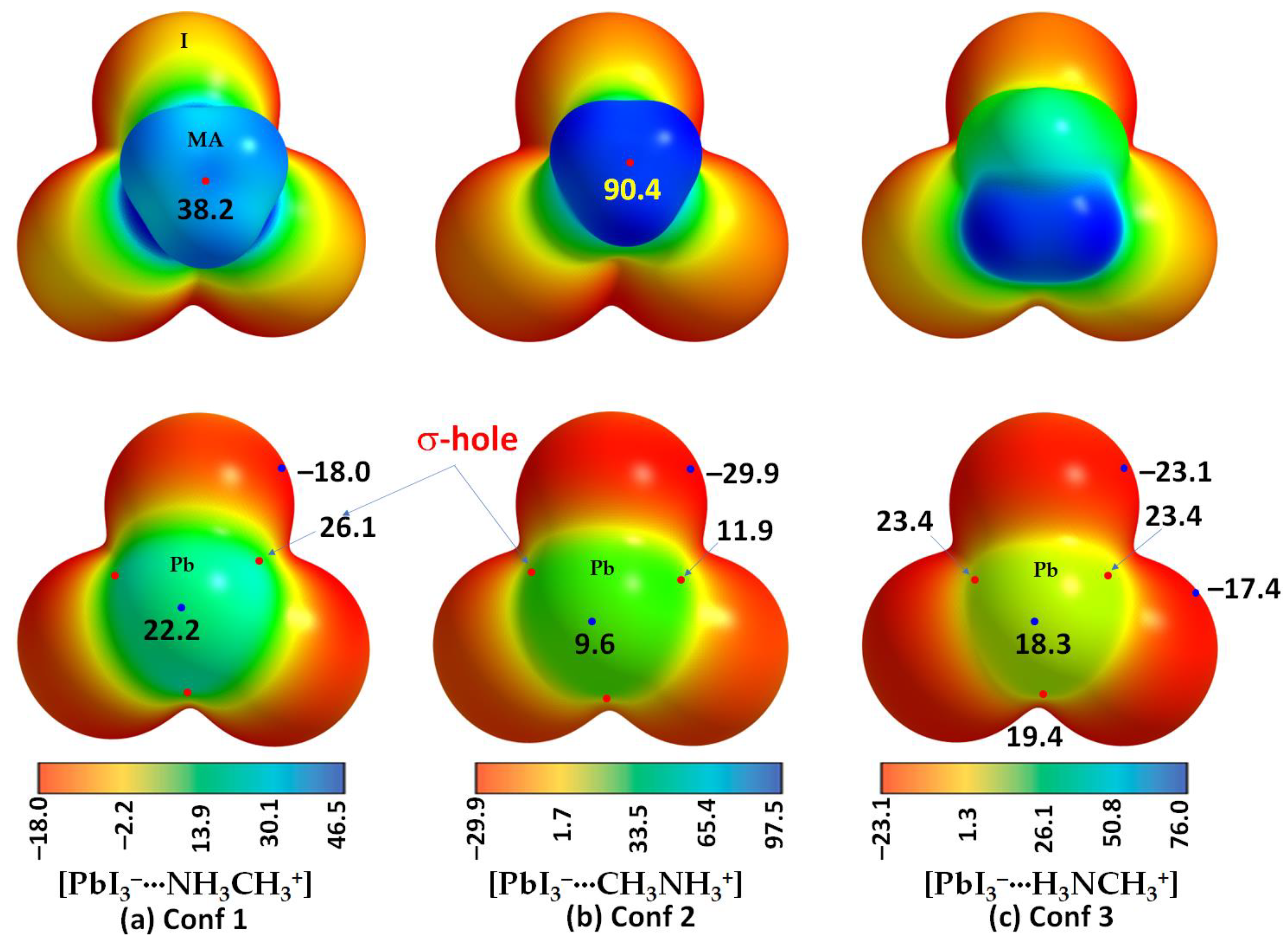
Figure 1. The unit cell (left) and 2 × 2 supercell (right) structure of cubic MAPbI3 in the high-temperature phase (T > 330 K [95]), showing the orientation of the organic cation along the (a) (111) and (b) (011) directions [25]. (c) Two different polyhedral views of the low-temperature orthorhombic phase of fully relaxed (PBEsol) geometry of MAPbI3, with the titling angle (in degrees), ∠Pb–I–Pb, along two crystallographic directions (see ESI for details), obtained using the VASP code (version 5.4) [96,97,98,99,100]. Each polyhedron represents the PbI64− octahedron. Three types of bonds (coordinate, tetrel and hydrogen bonds) are marked in the polyhedral model in (a).
Ijms 24 10554 g001
Figure 2. [ωB97X-D/def2-TZVPPD] level fully relaxed geometries of [CH3NH3+•PbX3] (X = F, Cl, Br, I) ion pairs, including (a) [I3Pb···NH3CH3]; (b) [I3Pb···CH3NH3]; (c) [I3Pb···H3NCH3]; (d) [Br3Pb···NH3CH3]; (e) [Br3Pb···CH3NH3]; (f) [Br3Pb···H3NCH3]; (g) [Cl3Pb···NH3CH3]; (h) [Cl3Pb···CH3NH3]; (i) [Cl3Pb···H3NCH3]; (j) [F3Pb···NH3CH3]; (k) [F3Pb···CH3NH3]; (l) [F3Pb···H3NCH3]. Shown are selected coordinate and hydrogen bond distances (solid and dotted lines, respectively) in Å and hydrogen bond angles in degrees. The relative energies (ΔE) with respect to the most stable conformer for each series with a given halogen derivative are shown in kcal mol−1. Atom labeling is shown for selected systems.
Ijms 24 10554 g002
Figure 3. [ωB97X-D/def2-TZVPPD] level potential on the electrostatic surface of the three conformations of [CH3NH3+•PbI3]: (a) [PbI3···NH3CH3+]; (b) [PbI3···CH3NH3+]; and (c) [PbI3···H3NCH3+]. The methyl, ammonium and both groups of MA are facing the reader in the top panel of (a), (b) and (c), respectively. The Pb atom is facing the reader in the bottom panel of all three MESP plots shown in (ac). Values on the color bar are in kcal mol−1. Atom labeling is shown for selected systems.
Ijms 24 10554 g003
Figure 4. [ωB97X-D/def2-TZVPPD] level QTAIM’s molecular graphs for [CH3NH3+•PbX3] (X = F, Cl, Br, I) ion pairs in the conformational space, including (a) [I3Pb···NH3CH3]; (b) [I3Pb···CH3NH3]; (c) [I3Pb···H3NCH3]; (d) [Br3Pb···NH3CH3]; (e) [Br3Pb···CH3NH3]; (f) [Br3Pb···H3NCH3]; (g) [Cl3Pb···NH3CH3]; (h) [Cl3Pb···CH3NH3]; (i) [Cl3Pb···H3NCH3]; (j) [F3Pb···NH3CH3]; (k) [F3Pb···CH3NH3]; (l) [F3Pb···H3NCH3]. The bond paths are shown as solid and dotted lines, respectively, in atom colors, and bond critical points (bcps) as tiny spheres in green between bonded atomic basins. Values (in a.u.) represent the charge density (ρb), the Laplacian of the charge density (∇2ρb) and the total energy density (Hb) at bcps. Atom labeling is shown for each case.
Ijms 24 10554 g004
Figure 5. [ωB97X-D/def2-TZVPPD] level IGM-δginter isosurface plots of the three conformations of [CH3NH3+•PbI3]: (a) [PbI3···NH3CH3+]; (b) [PbI3···CH3NH3+]; (c) [PbI3···H3NCH3+]. Shown in (d) are the IGM-δginter isosurface plots for [PbI3···H3NCH3+], in which different isovalues of IGM are shown. Labeling of selected atoms is shown in (a).
Ijms 24 10554 g005
Figure 6. [ωB97X-D/def2-TZVPPD] level fully relaxed gas phase geometries of (a) [CH3NH3+•PbI3]2; (b) [CH3NH3+•PbBr3]2; (c) [CH3NH3+•PbCl3]2; and (d) [CH3NH3+•PbF3]2. Shown in (df) are the low-temperature orthorhombic structures of MAPbI3, MAPbBr3 and MAPbCl3. Selected bond lengths (Å) and bond angles (degrees) are shown in (ad), and the tilting angle (degrees) is shown in (eg). The H atoms in MA are missing in the crystal structure of MAPbBr3.
Ijms 24 10554 g006
Figure 7. (Left) [ωB97X-D/def2-TZVPPD] computed 0.001 a.u. mapped electrostatic potential on the molecular surfaces of (a) [CH3NH3+•PbI3]2; (b) [CH3NH3+•PbBr3]2; (c) [CH3NH3+•PbCl3]2; and (d) [CH3NH3+•PbF3]2. (Right) QTAIM-based molecular graphs of the corresponding systems, respectively. (The bond critical points between atomic basins are shown as tiny spheres in green, and bond paths in atom colors.) Values on the color bar are in kcal mol−1, with the surface involving the fragment Pb–X···Pb–X facing the reader.
Ijms 24 10554 g007
Table 1. Selected [ωB97X-D/def2-TZVPPD] computed 0.001 a.u. isoelectronic density envelope mapped potential maxima and minima (kcal mol−1) on the electrostatic surfaces of ion pairs X3Tt···MA (X = I, Br, Cl, F; Tt = Pb, Sn, Ge, Si; MA = NH3CH3+). The 0.0015 a.u. isoelectronic density envelope mapped potentials are given in parentheses for selected systems.
Ion PairsVS,max(X–Tt)VS,max(X–Tt)VS,max(X–Tt)VS,min(Tt)VS,max(N-C)/VS,max(C-N)VS,min(X)VS,min(X)
I3Pb···NH3CH326.126.126.122.238.2−18.0
I3Pb···CH3NH311.911.911.99.690.4−29.9
I3Pb···H3NCH323.423.419.418.3---−23.1−17.4
Br3Pb···NH3CH326.626.626.622.236.4−21.2
Br3Pb···CH3NH310.410.410.47.788.3−34.1
Br3Pb···H3NCH323.023.019.117.4---−27.2−21.5
Cl3Pb···NH3CH326.126.126.121.034.9−23.8
Cl3Pb···CH3NH38.38.38.35.186.6−37.0
Cl3Pb···H3NCH321.821.817.915.5---−30.5−26.9
F3Pb···NH3CH322.822.822.814.827.4−37.6
F3Pb···CH3NH3−0.4 (4.1)−0.4 (4.1)−0.4 (4.1)−5.7 (−4.2)79.6 (83.8)−53.1 (−57.0)
F3Pb···H3NCH316.116.112.56.8---−39.2−47.5
I3Sn···NH3CH315.615.615.65.339.5−16.9
I3Sn···CH3NH30.50.50.5−7.991.4−30.0
I3Sn···H3NCH312.512.59.51.6---−22.2−17.2
Br3Sn···NH3CH315.515.515.53.838.2−19.8
Br3Sn···CH3NH3−1.6 (3.6)−1.6 (3.6)−1.6 (3.6)−11.1 (−10.1)89.8 (94.4)−33.8 (−34.7)
Br3Sn···H3NCH311.511.58.6−0.7---−25.8−20.9
Cl3Sn···NH3CH314.614.614.61.737.2−22.1
Cl3Sn···CH3NH3−4.0 (1.1)−4.0 (1.1)−4.0 (1.1)−14.8 (−14.2)88.5 (93.0)−35.8 (−37.8)
Cl3Sn···H3NCH310.110.17.2−3.6---−28.7---
F3Sn···NH3CH311.511.511.5−5.431.6−34.6
F3Sn···CH3NH3−11.7 (−6.9)−11.7 (−6.9)−11.7 (−6.9)−25.8 (−26.4)82.8 (---)−50.8 (−54.4)
F3Sn···H3NCH35.35.33.3−12.3 −36.3−44.0
I3Ge···NH3CH37.07.07.0−3.040.6−17.3
I3Ge···CH3NH3−8.2 (−3.8)−8.2 (−3.8)−8.2 (−3.8)−16.0 (−15.3)92.5 (97.1)−30.9 (−31.1)
I3Ge···H3NCH34.24.21.4−6.1---−22.2−17.8
Br3Ge···NH3CH36.16.16.1−5.539.7−19.9
Br3Ge···CH3NH3−11.3−11.3−11.3−20.790.9−35.4
Br3Ge···H3NCH32.4 (7.4)2.4 (7.4)−0.3 (4.3)−9.6 (−8.9)---−25.4 (−26.4)−21.4 (−22.4)
Cl3Ge···NH3CH34.84.84.8−8.739.0−21.7
Cl3Ge···CH3NH3−14.2−14.2−14.2−25.389.7−37.9
Cl3Ge···H3NCH30.6 (5.9)0.6 (5.9)−1.8 (2.7)−13.4 (−13.1)---−27.6 (−29.0)−24.1 (−25.1)
F3Ge···NH3CH3−0.3 (4.7)−0.3 (4.7)−0.3 (4.7)−19.2 (−19.9)35.4 (38.0)−33.1 (−35.5)
F3Ge···CH3NH3−23.8−23.8−23.8−39.585.2−50.3
F3Ge···H3NCH3−6.1−6.1−6.7−25.1---−41.1−35.3
I3Si···NH3CH3−0.8 (3.3)−0.8 (3.3)−0.8 (3.3)−15.8 (−16.0)41.8 (44.7)−16.6 (−16.7)
I3Si···CH3NH3−16.3−16.3−16.3−29.193.4−30.6
Br3Si···NH3CH3−3.1 (1.3)−3.1 (1.3)−3.1 (1.3)−20.5 (−21.3)41.3 (44.2)−19.2 (−19.7)
Br3Si···CH3NH3−20.9−20.9−20.9−35.792.3−35.0
Cl3Si···NH3CH3−5.3 (−1.0)−5.3 (−1.0)−5.3 (−1.0)−25.5 (−26.7)41.3 (44.2)−21.0 (−21.7)
Cl3Si···CH3NH3−24.6−24.6−24.6−41.991.7−37.6
Cl3Si···H3NCH3−9.8−9.8−10.8−29.8---−24.5−27.5
F3Si···NH3CH3−12.6−12.6−12.6−41.240.8−32.1
F3Si···CH3NH3−35.0−35.0−35.0−60.089.6−50.6
F3Si···H3NCH3−17.70−17.70−15.0−45.8---−34.2−39.4
Table 2. The uncorrected and BSSE-corrected interaction energies, ΔE and ΔE(BSSE), respectively, of methylammonium tetrel halide perovskite ion pairs, obtained with [ωB97X-D/def2-TZVPPD]. Values in kcal mol−1.
SystemInteraction TypeΔEΔE(BSSE)
I3Pb···NH3CH3I···H(N)−104.95−104.85
I3Pb···CH3NH3I···H(C)−76.42−76.33
I3Pb···H3NCH3I···H(N), I···H(C)−97.64−97.53
Br3Pb···NH3CH3Br···H(N)−111.04−110.66
Br3Pb···CH3NH3Br···H(C)−80.05−79.77
Br3Pb···H3NCH3Br···H(N), Br···H(C)−102.95−102.62
Cl3Pb···NH3CH3Cl···H(N)−115.95−115.66
Cl3Pb···CH3NH3Cl···H(C)−82.78−82.55
Cl3Pb···H3NCH3Cl···H(N), Cl···H(C)−107.24−106.99
F3Pb···NH3CH3F···H(N)−138.54−138.23
F3Pb···CH3NH3F···H(C)−94.39−94.18
F3Pb···H3NCH3F···H(N), F···H(C)−126.47−126.2
I3Sn···NH3CH3I···H(N)−103.12−103.01
I3Sn···CH3NH3I···H(C)−75.02−74.93
I3Sn···H3NCH3I···H(N), I···H(C)−96.07−95.96
Br3Sn···NH3CH3Br···H(N)−108.39−108.01
Br3Sn···CH3NH3Br···H(C)−78.17−77.89
Br3Sn···H3NCH3Br···H(N), Br···H(C)−100.76−100.44
Cl3Sn···NH3CH3Cl···H(N)−112.48−112.19
Cl3Sn···CH3NH3Cl···H(C)−80.43−80.2
Cl3Sn···H3NCH3Cl···H(N), Cl···H(C)−104.45−104.19
F3Sn···NH3CH3F···H(N)−131.44−131.11
F3Sn···CH3NH3F···H(C)−90.37−90.15
F3Sn···H3NCH3F···H(N), F···H(C)−121.08−120.79
I3Ge···NH3CH3I···H(N)−101.91−101.74
I3Ge···CH3NH3I···H(C)−74.2−74.05
I3Ge···H3NCH3I···H(N), I···H(C)−95.31−95.13
Br3Ge···NH3CH3Br···H(N)−106.63−106.22
Br3Ge···CH3NH3Br···H(C)−77.07−76.74
Br3Ge···H3NCH3Br···H(N), Br···H(C)−99.64−99.26
Cl3Ge···NH3CH3Cl···H(N)−110.15−109.82
Cl3Ge···CH3NH3Cl···H(C)−79.01−78.74
Cl3Ge···H3NCH3Cl···H(N), Cl···H(C)−102.88−102.56
F3Ge···NH3CH3F···H(N)−125.21−124.92
F3Ge···CH3NH3F···H(C)−87.26−87.04
F3Ge···H3NCH3F···H(N), F···H(C)−116.94−116.66
I3Si···NH3CH3I···H(N)−100.36−100.25
I3Si···CH3NH3I···H(C)−73.01−72.91
Br3Si···NH3CH3Br···H(N)−104.19−103.86
Br3Si···CH3NH3Br···H(C)−75.28−75.03
Cl3Si···NH3CH3Cl···H(N)−106.61−106.34
Cl3Si···CH3NH3Cl···H(C)−76.58−76.37
Cl3Si···H3NCH3Cl···H(N), Cl···H(C)−99.92−99.65
F3Si···NH3CH3F···H(N)−115.3−115.02
F3Si···CH3NH3F···H(C)−81.46−81.24
F3Si···CH3NH3F···H(N), F···H(C)−109.02−108.77
Table 3. Selected QTAIM-based topological charge density properties associated with the tetrel and pnictogen bonds of [CH3NH3+•TtX3]2 (Tt = Pb, Sn, Ge, Si; X = I, Br, Cl, F), obtained with [ωB97X-D/def2-TZVPPD]. Values in a.u. a,b.
SystemTetrel Bondρb2ρbHbPnictogen Bondρb2ρbHb
[CH3NH3+•PbI3]2Pb···I0.01440.02720.0002N···I0.00580.01890.0009
[CH3NH3+•PbBr3]2Pb···Br0.01630.03680.0003N···Br0.00640.02300.0011
[CH3NH3+•PbCl3]2Pb···Cl0.01870.04960.0007N···Cl0.00660.02570.0013
[CH3NH3+•PbF3]2Pb···F0.03420.13730.0002N···F0.00620.02940.0016
[CH3NH3+•SnI3]2Sn···I0.01080.01910.0003N···I0.00700.02310.0010
[CH3NH3+•SnBr3]2Sn···Br0.01130.02340.0004N···Br0.00800.02930.0012
[CH3NH3+•SnCl3]2Sn···Cl0.01240.02920.0008N···Cl0.00860.03390.0015
[CH3NH3+•SnF3]2Sn···F0.02830.09650.00005N···F0.00940.04630.0023
[CH3NH3+•GeI3]2Ge···I0.00850.01930.0007N···I0.00770.02530.0010
[CH3NH3+•GeBr3]2Ge···Br0.00900.01740.0005N···Br0.00900.03260.0013
[CH3NH3+•GeCl3]2Ge···Cl0.00820.02110.0010N···Cl0.00960.03780.0016
[CH3NH3+•GeF3]2Ge···F0.01250.04150.0014N···F0.01160.05940.0027
[CH3NH3+•SiI3]2Si···I0.00680.01340.0005N···I0.00830.02740.0190
[CH3NH3+•SiBr3]2Si···Br0.00540.01250.0006N···Br0.00960.03510.0263
[CH3NH3+•SiCl3]2Si···Cl0.00260.00630.0004N···Cl0.01050.04180.0376
[CH3NH3+•SiF3]2H···Si b0.02280.0281−0.0018N···F0.01020.04960.0669
a The properties include the charge density (ρb), the Laplacian of the charge density (∇2ρb) and the total energy density (Hb). b A hydrogen bond (see Figure S11d).
Table 4. [ωB97X-D/def2-TZVPPD] level uncorrected and BSSE-corrected interaction energies, ΔE and ΔE(BSSE), respectively (kcal mol−1), for the [CH3NH3+•TtX3]2 (Tt = Pb, Sn, Ge, Si; X = I, Br, Cl, I) binary complexes examined.
SystemInteraction Type aΔEΔE(BSSE)
[CH3NH3+•PbI3]2Pb···I−17.11−16.83
[CH3NH3+•PbBr3]2Pb···Br−17.78−17.26
[CH3NH3+•PbCl3]2Pb···Cl−18.26−17.85
[CH3NH3+•PbF3]2Pb···F−25.21−24.73
[CH3NH3+•SnI3]2Sn···I−13.80−13.51
[CH3NH3+•SnBr3]2Sn···Br−13.40−12.87
[CH3NH3+•SnCl3]2Sn···Cl−12.99−12.59
[CH3NH3+•SnF3]2Sn···F−17.22−16.72
[CH3NH3+•GeI3]2Ge···I−12.11−11.66
[CH3NH3+•GeBr3]2Ge···Br−11.08−10.41
[CH3NH3+•GeCl3]2Ge···Cl−10.01−9.50
[CH3NH3+•GeF3]2Ge···F−9.09−8.60
[CH3NH3+•SiI3]2Si···I−10.20−9.92
[CH3NH3+•SiBr3]2Si···Br−8.81−8.33
[CH3NH3+•SiCl3]2Si···Cl−7.49−7.15
[CH3NH3+•SiF3]2H···Si b−14.48−14.35
a See text for discussion. b A hydrogen bond (see Figure S11d).
Disclaimer/Publisher’s Note: The statements, opinions and data contained in all publications are solely those of the individual author(s) and contributor(s) and not of MDPI and/or the editor(s). MDPI and/or the editor(s) disclaim responsibility for any injury to people or property resulting from any ideas, methods, instructions or products referred to in the content.

