Article

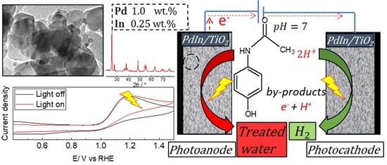
Pd:In-Doped TiO2 as a Bifunctional Catalyst for the Photoelectrochemical Oxidation of Paracetamol and Simultaneous Green Hydrogen Production

by
Nicolás Sacco
1,
Alexander Iguini
2,
Ilaria Gamba
2,
Fernanda Albana Marchesini
1 and
Gonzalo García
2,*
1
Instituto de Investigaciones en Catálisis y Petroquímica, INCAPE (UNL-CONICET), Facultad de Ingeniería Química, Santiago del Estero 2829, Santa Fe 3000, Argentina
2
Departamento de Química, Instituto Universitario de Materiales y Nanotecnología, Universidad de La Laguna (ULL), P.O. Box 456, 38200 La Laguna, Spain
*
Author to whom correspondence should be addressed.
Molecules 2024, 29(5), 1073; https://doi.org/10.3390/molecules29051073
Submission received: 22 January 2024 / Revised: 24 February 2024 / Accepted: 27 February 2024 / Published: 29 February 2024
(This article belongs to the Special Issue Photocatalytic Materials and Photocatalytic Reactions)

Abstract

:
The integration of clean energy generation with wastewater treatment holds promise for addressing both environmental and energy concerns. Focusing on photocatalytic hydrogen production and wastewater treatment, this study introduces PdIn/TiO2 catalysts for the simultaneous removal of the pharmaceutical contaminant paracetamol (PTM) and hydrogen production. Physicochemical characterization showed a high distribution of Pd and In on the support as well as a high interaction with it. The Pd and In deposition enhance the light absorption capability and significantly improve the hydrogen evolution reaction (HER) in the absence and presence of paracetamol compared to TiO2. On the other hand, the photoelectroxidation of PTM at TiO2 and PdIn/TiO2 follows the full mineralization path and, accordingly, is limited by the adsorption of intermediate species on the electrode surface. Thus, PdIn-doped TiO2 stands out as a promising photoelectrocatalyst, showcasing enhanced physicochemical properties and superior photoelectrocatalytic performance. This underscores its potential for both environmental remediation and sustainable hydrogen production.

Graphical Abstract

1. Introduction

Energy production and water availability pose significant challenges for future generations. The global consumption of both resources is experiencing substantial growth, driven by population increases and improved living standards. The combustion of fossil fuels releases greenhouse gases and other pollutants into the atmosphere, resulting in critical consequences for the environment. On the other hand, water availability is threatened by the presence of contaminants in wastewater and the lack of water sanitation solutions.
The Sustainable Development Goals (SDGs) set forth by the United Nations for 2030 include specific objectives related to energy consumption (SDG 7: Affordable and Clean Energy) and water pollution (SDG 6: Clean Water Sanitation). Renewable energies could be a key part of the solution for sustainable energy production if electricity storage is ensured. Hydrogen has emerged as a highly promising renewable fuel due to its high energy content, lack of environmental hazards, and, most importantly, its ability to be produced from water [1,2]. The production of green hydrogen is a promising way to supply and distribute intermittently generated energy through fuel cells. However, its production through water splitting is not cost-effective due to the large amounts of energy required for the oxygen evolution reaction (OER) at the anode. It is important to consider that in the case of water splitting, the thermodynamic potential needed to break down water into oxygen and hydrogen is 1.23 V. However, high overpotentials are usually employed to overcome the slow kinetics of the OER [3]. Photoelectrocatalytic production of hydrogen by oxidizing organic or inorganic compounds at the anode can be achieved without the need for electrical input, but current catalysts do not meet the requirements to approach viability goals. On the other hand, the potential required for the degradation of contaminants depends on the nature and concentration of the contaminants, the nature of the photoelectrocatalyst, and the efficiency of the process used [4].
Electrocatalytic hydrogen production has emerged as a popular method for hydrogen generation [5]. However, there are several issues, including cost-effectiveness, associated with these techniques. To address the dual challenges of the energy crisis and environmental pollution, sustainable photocatalytic hydrogen production has shown promise [6,7]. However, efficient photocatalytic hydrogen generation typically requires the use of external sacrificial agents or donors, such as alcohols or organic acids, to scavenge holes and reduce recombination [8]. The addition of these sacrificial agents increases the cost of hydrogen evolution, making it economically viable but less practical in the long run [9]. Thus, for sustainable and efficient hydrogen production, there are two main requirements to achieve. Firstly, the photocatalyst must possess efficient electron–hole separation, numerous active reaction sites, and high visible light activity [10,11], which is crucial for effective hydrogen generation. The second challenge involves the recovery or generation of hydrogen energy from wastewater, enabling environmentally friendly and sustainable energy production combined with water treatment on a larger scale. This integrated approach holds promise for addressing both energy and environmental concerns.
Various catalysts for efficient photocatalytic H2 generation have been synthesized by different authors. Meng et al. [12] developed Ni12P5/ZnIn2S4 (NP/ZIS) heterostructures using a hydrothermal method, demonstrating visible-light-driven photocatalytic splitting of benzyl alcohol into H2 and benzaldehyde. The use of 7% NP/ZIS significantly improved the thermodynamics and kinetics of H2 production compared to pure water splitting and individual ZIS, attributed to increased surface area, porous structure, creation of defect states (zinc vacancies), and the enhancement of the NP co-catalyst. Amorphous TiO2 and Co-ZnIn2S4 were combined to form a heterojunction, improving photocarrier separation efficiency and catalyst stability. The introduction of amorphous TiO2 induced oxygen vacancies, enhancing carrier density. Additionally, MoP nanoparticles were introduced as co-catalysts, serving as hydrogen production sites and achieving efficient hydrogen production [13].
Long et al. [14] investigated nanostructured polymeric carbon nitride (PCN) for visible-light-driven photocatalytic hydrogen evolution, attributing improved activity to increased BET specific surface area, higher active site quantity, and accelerated transfer and separation of photo-excited charge carriers. Additionally, Zheng et al. [15] demonstrated the excellent photocatalytic activity of Au/ZnO nanomaterial in bisphenol A degradation and photoelectrochemical water splitting. The enhanced activities were linked to heightened light absorption and unique charge transfer of photogenerated electrons, effectively reducing the recombination rate and prolonging the lifetime of photo-excited carriers.
Contaminants of emerging concern (CECs) are increasingly being detected in water sources worldwide, posing significant challenges to water quality and human health. These CECs include a wide range of pollutants, such as pharmaceuticals, personal care products, pesticides, industrial chemicals, and microplastics, which can enter water bodies through various pathways [16,17]. The presence of CECs in water raises concerns for both ecological and human health. These contaminants can have adverse effects on aquatic ecosystems, including the disruption of endocrine systems, alteration of reproductive behaviors, and changes in the composition of microbial communities. In terms of human health, exposure to CECs through drinking water consumption or recreational activities in contaminated water bodies can pose risks, particularly for vulnerable populations such as children and pregnant women [18].
Paracetamol, also known as acetaminophen, is a widely used over-the-counter medication for pain relief and fever reduction. Like many pharmaceuticals, it can enter the environment through various pathways, including improper disposal, excretion, and wastewater treatment plant effluents. While it is generally considered safe for human use when taken at recommended doses, the presence of PTM in water bodies as a CEC is a topic of growing interest and research. The presence of acetaminophen in aquatic environments can have adverse effects on aquatic organisms. Even at low concentrations, it can disrupt the endocrine systems of fish and other aquatic organisms, affecting their reproductive capabilities [19].
Thus, utilizing PTM as a sacrificial agent in photocatalytic hydrogen evolution serves the purposes of both clean energy generation and wastewater treatment.
Photoelectrochemical oxidation (PECO) is indeed a promising technique for the removal of PTM from water. PECO involves the use of a photoactive electrode, typically a semiconductor material, which generates reactive oxygen species (ROS) upon exposure to light. These ROS, such as hydroxyl radicals, play a crucial role in the degradation of organic contaminants like PTM [20].
Since the discovery of TiO2’s ability for water-splitting and photocatalytic degradation of organic compounds, numerous semiconductors have been studied for environmental and energy applications. TiO2 is the most extensively investigated due to its chemical stability, low cost, and good photocatalytic efficiency [21]. However, TiO2 does have a limitation in its optical response. With a large band gap (E.g., ~3.2 eV), TiO2 primarily responds to UV light, which accounts for only 5% of solar energy [22]. To address this issue, various modifications of TiO2 have been extensively studied to enhance its wavelength range response, promote charge generation, and facilitate efficient charge separation to minimize recombination [23]. Techniques for TiO2 modifications include metal loading, ion doping, semiconductor coupling, and dye sensitization. Depositing precious metals or rare-earth metals onto semiconductors is a widely investigated approach to enhance the photocatalytic properties of TiO2 [24]. This method offers two main advantages: the formation of a Schottky junction for efficient charge separation and the localized surface plasmon resonance (LSPR) effect, which promotes enhanced charge generation through the absorption of visible light.
Pd and Pd-In catalysts have been widely reported in the catalytic reduction and electrochemical reduction of inorganic ions present in water [25]. It has been demonstrated that the Pd-In combination can hydrogenate nitrate ions into nitrites in water [26]. On the other hand, Pd has attracted significant attention as it is one of the platinum-group metals with high catalytic activity for the HER [27]. It is important to note that most of the catalysts, either mono- or bimetallic, based on Pd for the electrocatalytic production of H2 imply the use of high metal loadings, which considerably increases the cost of these technologies. This work evaluates the catalytic performance of PdIn-doped TiO2 catalysts (Pd, 1 wt.%, In 0.25 wt.%) in the photoelectrochemical oxidation of PTM and the simultaneous HER. The reaction mechanism, both for PTM oxidation and HER, and the stability of the catalyst are discussed.

2. Results and Discussion

2.1. Characterization

2.1.1. UV-DRS Analysis

To evaluate the absorbance properties of TiO2 and PdIn/TiO2 synthesized in this study, UV–Vis diffuse reflectance spectra (DRS) were measured (Figure 1). The absorption band edge of TiO2 occurs at approximately 400 nm. The addition of PdIn leads to an increase in absorption at longer wavelengths within the visible range. The band gap values of TiO2 and PdIn/TiO2 were 3.67 and 3.47 eV, respectively. The lowest band gap value obtained after the impregnation of PdIn onto TiO2 would indicate that the Pd and In deposition enhances the light absorption capability, resulting in a possible higher catalytic activity when compared to TiO2 alone. This behavior could be related to the Fermi levels of Pd, which are lower than those of TiO2, facilitating the efficient transfer of photogenerated electrons from the conduction band of TiO2 to the metal particles. This process of electron trapping greatly diminishes the rate of electron–hole recombination, leading to enhanced photocatalytic reactions.

2.1.2. Physicochemical Properties

Morphology and elemental analysis of PdIn/TiO2 were studied through SEM–EDS and HRTEM techniques, respectively. Figure 2a shows an SEM–EDS micrograph of the PdIn/TiO2 catalyst and the corresponding mappings. A homogeneous distribution of the materials was obtained. Indeed, a high distribution of Pd and In on the TiO2 particles is perceived, with an average wt.% composition of 0.85 ± 0.07 and 0.22 ± 0.04, respectively, and a Pd:In atomic ratio close to the nominal value was detected. Figure 2b shows the HRTEM micrograph of the PdIn/TiO2 catalyst. Particles with an average size of 18 nm are observed and depicted in the particle size distribution graph (Figure S1). Furthermore, particles with smaller sizes (~5 nm) are discerned and may be ascribed to Pd and/or In-based species.
The surface area and pore volume of PdIn/TiO2, obtained from BET analysis, were 48.84 m2/g and 0.0015 cm3/g, respectively. For commercial TiO2, a surface area of 48.47 m2/g was reported, a similar value [28]. Therefore, no diminution of the surface area is perceived after metal deposition onto TiO2 material. Figure S2 shows nitrogen adsorption isotherms of TiO2 and PdIn/TiO2 materials. N2 adsorption isotherms align with type II, as per the IUPAC classification. These isotherms are indicative of non-porous or macroporous solids, exhibiting low or negligible microporosity and unrestricted multilayer adsorption.
XRD patterns of PdIn/TiO2 and the bare support were assayed to elucidate the crystalline phases present. Figure 3 shows the corresponding diffractograms, respectively. Anatase (JCPDS 00-021-1272) and rutile (JCPDS 00-021-1276) phases were detected in both TiO2 and PdIn/TiO2 catalysts. No crystalline phases corresponding to Pd or In were detected, which could be due to the low metal loading, the high dispersion of the material on the support, and/or the amorphous nature of the dispersed species. The crystallite size of both phases, anatase (plane 1 0 1, 2θ = 25.281°) and rutile (plane 1 1 0, 2θ = 27.477°), for PdIn/TiO2 and TiO2 were calculated using the Scherrer equation. Crystallite sizes of 20.93 nm were obtained for the anatase phase of both catalysts. For the rutile phase of TiO2 and PdIn/TiO2, crystallite sizes of 25.6 and 31.4 nm, respectively, were obtained. This change of crystallite size in the rutile phase could be due to a strong interaction with Pd and In species or to their introduction into its crystalline network since the doping of the material could affect its electronic and structural properties and consequently the crystallite size [29,30,31].
The electroactive surface area was calculated by performing CVs at different scan rates in a potential range where no faradaic reaction occurs (i.e., capacitive currents are employed) by plotting the anodic and cathodic current densities at a fixed potential versus the scanning rate (see Figure S3 as an example for GC in the Supplementary Material). The same procedure was performed for TiO2 and PdIn/TiO2. The corresponding values of anodic and cathodic electrochemical double-layer capacitances (EDLCA and EDLCV, respectively) and electroactive surface areas for different electrodes, calculated using Equations (14) and (15) (see Experimental section), are summarized in Table 1. Considering the slopes obtained for each material, it can be observed that the PdIn/TiO2 catalyst reveals a higher ECSA than GC and TiO2.

2.2. Hydrogen Evolution Reaction

Figure 4 shows cyclic voltammograms performed at GC (black line), TiO2 (red line), and PdIn/TiO2 (blue line) between −0.3 V and 1.5 V in the electrolyte solution. As expected, the GC electrode reveals only capacitive currents in the potential range under study. On the other hand, TiO2 and PdIn/TiO2 catalysts show an increment of the cathodic current at potentials more negative than 0.0 V, which is associated with the HER. Interestingly, the presence of PdIn significantly improves the HER in the electrolyte solution. Indeed, PdIn/TiO2 develops double the current at −0.25 V compared with TiO2.
The photoelectrocatalytic performance of TiO2 (black lines) and PdIn/TiO2 (red lines) catalysts toward the HER was evaluated through chronoamperometry technique in the presence (light on) and absence (light of) of radiation at 0 and −0.1 V with an irradiation intermittence of 30 s (Figure 5).
TiO2 material develops low cathodic current and photocurrents at both studied potentials. Oppositely, the PdIn/TiO2 catalyst reveals high cathodic current values at both applied potentials and suitable photoactivity at 0.0 V. The decrease of the photoactivity of PdIn/TiO2 at −0.1 V suggests that the flat band potential is close. In addition, the PdIn/TiO2 catalyst develops similar cathodic current values over time, which indicates an appropriate photoelectrochemical stability and, thus, a suitable photoelectrocatalytic performance toward the HER.
A Tafel plot was employed to better understand the reaction kinetics and mechanism of the HER at the best catalyst developed in the current work. For this purpose, linear sweep voltammetry (LSV) was performed between 0.2 and −0.2 V at a sweep speed of 5 mV·s−1. Two reaction mechanisms are commonly discussed in the literature [32,33], denoted as Volmer–Heyrovsky and Volmer–Tafel. Both mechanisms have in common that hydrogen is adsorbed (Had) on the electrode through the electrochemical Volmer step but differ in the second stage. For the Volmer–Heyrovsky mechanism (Equation (1)), the Heyrovsky step (Equation (2)) involves the adsorbed hydrogen recombining with another proton from the solution to release an H2 molecule. On the other hand, the Volmer–Tafel mechanism consists of two consecutive Volmer steps and the Tafel step (Equation (3)) in a recombination step of two adjacent hydrogen adsorbates to form H2.
V o l m e r : H 2 O + e H a d + O H ,
H e y r o v s k y : H a d + H 2 O + e H 2 + O H ,
and
T a f e l : H a d + H a d H 2
Tafel slope (TS) values were employed to discern which reaction mechanism follows the HER at the PdIn/TiO2 catalyst. TS values of 120, 30, and 40 mV·dec−1 are associated with Volmer, Tafel, and Heyrovsky as the rate-determining step (RDS), respectively. Figure 6a shows the LSV recorded for PdIn/TiO2 performed at 5 mv·s−1 from 0.2 V to −0.2 V in the electrolyte solution. Figure 6b shows a TS close to 120 mV·dec−1, which is attributed to the Volmer step as the RDS during the HER at the PdIn/TiO2 catalyst. In this sense, the high TS may be attributed to the high amount of surface oxygenated species of TiO2, which may inhibit the first electron transfer step.

2.3. Paracetamol Oxidation Reaction

The photoelectrocatalytic activity of GCE, PdIn/TiO2, and TiO2 support towards the oxidation of PTM (100 ppm) was evaluated using cyclic voltammetry under irradiation and in the absence of irradiation. Figure 7 shows CV profiles of PTM electro-oxidation in the dark at GCE, TiO2, and PdIn/TiO2. As discussed above (see Figure 4), the presence of PTM does not change the catalytic performance toward the HER at PdIn/TiO2, and consequently, the catalytic active sites for the HER are not compromised.
PTM oxidation on GCE (blue line) exhibits an anodic current generation with an anodic peak at 1.1V, and an onset potential of 1.0 V. A quasi-reversible process with a peak-to-peak separation of ΔV = 250 mV was determined, as reported by Nematollahi et al. [34] for the same material and similar pH conditions. At more positive potentials than the anodic current peak, a large drop in current density is observed, showing a Cottrell behavior, indicating that the process is limited by diffusion of the species towards the electrode surface.
On the other hand, TiO2 (black line) and PdIn/TiO2 (red line) show an irreversible behavior toward the PTM oxidation with onset potentials of 1.0 V and ΔV = 750 and 420 mV, respectively. Evidently, at higher potentials than the anodic peak current, the oxidation behavior is different for GCE compared with TiO2-based materials. This suggests that the reaction mechanism at TiO2-based materials is limited by adsorbed species.
The same CV experiments were performed on TiO2 and PdIn/TiO2 but in the presence of light. The inset plot in Figure 7 compares voltammograms corresponding to the PTM oxidation at TiO2 and PdIn/TiO2 catalysts under the absence (solid lines) and the presence (dashed lines) of light. During the oxidation of PTM in the absence of light, at more positive potentials than the anodic peak, the current density slightly decreases (i.e., non-Cottrell behavior) with the rise of the applied potential, suggesting that the current is limited by kinetic. Conversely, in the presence of light, the current density remained almost constant at more positive potentials than the anodic peak, which implies that the current is limited by kinetics and suggests that adsorbed species are responsible. On the other hand, during the reverse scan, the presence of light made the system completely irreversible, i.e., no cathodic currents were discerned.
To better understand the kinetics and reaction mechanism of the PTM oxidation at all materials studied in the current work, rotating disk experiments at different rotational speeds were performed.
Figure 8a,b compares CV profiles of PTM oxidation at GCE performed at different sweep rates and rotational rates, respectively. These experiments demonstrate that the PTM oxidation process is diffusion-limited on the GCE since, as shown in Figure 8, the anodic current density reaches a constant diffusion value (IDIF), which increases with the growth of the rotational speed.
For GCE, Randles–Sevsick and Koutecky–Levich plots with the corresponding slope value are shown in Figure S4, respectively. Koutecky–Levich equation is shown in Equation (4), where I D I F is the limit current (A), I k   the kinetic current, and I l e v is expressed using Equation (5):
1 I D I F = 1 I l e v + 1 I k  
and
I l e v = 0.62 n F A D 2 / 3 ω 1 / 2 ν 1 / 6 C ,
where v is the kinematic viscosity, w is the angular frequency of rotation (rad·s−1), A is the disk electrode area (cm2), and other symbols have their conventional meanings. By plotting 1 I D I F   v s   ω 1 / 2 and obtaining from the literature for the kinematic viscosity of the electrolyte (0.012 cm2·s−1) [35] and the diffusion coefficient D (6.1 × 10⁻⁶ cm2·s−1) [36], the number of electrons transferred involved in the reaction yielded a value of 2, as reported by Nematollahi et al. [34]. Thus, this process could be associated with the reversible transformation of PTM into N-acetyl-p-benzoquinone amine (NAPQI) [34]:
C 8 H 9 NO 2 C 8 H 7 NO 2 + 2 H + + 2 e .
Figure 8c,d compares CV profiles of PTM oxidation at PdIn/TiO2 performed at different sweep rates and rotational rates, respectively. On the other hand, the anodic peak potential for TiO2 and PdIn/TiO2 was plotted as a function of the scan rate, and a linear trend was discerned, which suggests that the process is limited by the adsorption of species on the electrode surface. The number of electrons (n) transferred to the surface of the electrode was calculated through the Laviron equation for an irreversible process, where α is the electron-transfer coefficient (0.5), and n is the number of electrons involved in the redox process [37]:
E p A = R T 1 α n F log ( v ) .
For both TiO2-based electrodes, the number of transferred electrons was 1, and the subsequent reaction is the most plausible to occur:
C 8 H 9 NO 2   ( C 8 H 8 NO 2 ) ad + H + + 1 e .
Then, the adsorbed species may follow subsequent reactions at more positive potentials:
( C 8 H 8 NO 2 ) ad ( C 8 H 7 NO 2 ) ad + H + + 1 e ,
( C 8 H 7 NO 2 ) ad C 8 H 7 NO 2 ,
and
( C 8 H 7 NO 2 ) ad + 14 H 2 O     8 CO 2 + 1 2 N 2 + 35 H + + 35 e .
Equation (10) seems to be facile at GCE, while the opposite happens at TiO2-based electrodes, and accordingly, the adsorbate path is favored. In this sense, Equation (11) indicates the global reaction toward the total mineralization of paracetamol, which is expected to follow the adsorbate route via deprotonation processes. In this context, it is important to note that the presence of radiation at TiO2-based electrodes completely inhibits the pathway toward soluble species (i.e., Equation (10)), and consequently, no cathodic peaks are detected during the reverse sweep.
In this regard, Figure 8d suggests the aforementioned phenomenon, as a subsequent increment in the anodic current is perceived with the rise of applied potential in the presence of light. Remarkably, the same current values were obtained at rotation rates higher than 750 rpm, and no inhibition was discerned in the subsequent cycles. Therefore, the adsorbate route seems to predominate in TiO2-based catalysts. Furthermore, the addition of a small amount of PdIn into TiO2 not only increases the catalytic efficiency toward PTM oxidation but also intensely raises the HER, which is not inhibited in the presence of the organic molecule.
Finally, to test the catalytic stability of PdIn/TiO2 toward the degradation of PTM in the absence and presence of light, a current transient was recorded at 1.2 V and depicted in Figure 9. An initial decrease in the anodic current density in the absence of light is observed, which rises and remains almost constant when the system is exposed to light. This indicates an improved catalyst performance toward PTM photoelectroxidation.

3. Experimental

3.1. Catalyst Synthesis

The bimetallic catalyst supported on titania was prepared using the conventional wet impregnation method by co-impregnating Pd:In in a 1:0.25 wt.% ratio relative to the support (TiO2), followed by calcination and reduction.
A solution of PdCl2 (Sigma Aldrich, St. Louis, MO, USA, p.a.) and InCl3 (Sigma Aldrich, 99.9%) was utilized to achieve the desired bimetallic catalyst. The process involved the addition of a specific mass of TiO2 support (Degussa, Zürich, Germany, P25, 48 m2/g) to a container containing water, along with a volume of concentrated Pd and In solutions, to attain the desired weight percentages of the metals, namely 1.00% Pd and 0.25% In.
Once the mixture was homogeneous and the solvent was evaporated, the material was dried overnight at 80 °C, and then calcined at 500 °C for 4 h. Finally, it was reduced using a 0.2 M solution of hydrazine hydrate and washed several times with deionized water. The material was left to dry overnight at 80 °C and named PdIn/TiO2.

3.2. Physicochemical Characterization

X-ray diffraction (XRD), energy-dispersive X-ray spectroscopy (EDX), N2 adsorption–desorption isotherms, scanning electron microscopy (SEM), and transmission electron microscopy (TEM) were employed for the physicochemical characterization of catalysts.
XRD powder spectra were generated utilizing the X’Pert PRO X-ray diffractometer (PANalytical, Tokyo, Japan) to ascertain the crystal structure. The measurements were conducted using CuKα radiation (λ = 1.5405 Å) and the X’pert high score plus diffraction software, version 1.0f. The 2θ data were collected in the range of 20° to 100° with a scanning rate of 0.04° s−1. The identification of crystalline phases was achieved by comparing the experimental diffraction patterns with those in the Joint Committee on Powder Diffraction Standards (JCPDS).
Morphological characterization of the synthesized catalysts was performed using SEM images recorded with a ZEISS EVO 15 SEM with a 2 nm resolution and Oxford X-MAX 50 mm2 EDX.
TEM studies were conducted using a JEOL JEM 2100 electron microscope operating at 100 kV. The samples were diluted in ethanol and placed in a conventional TEM copper grid with a thin holey carbon film.
N2 adsorption–desorption isotherms of the carbon supports were measured at −196 °C using Micromeritics ASAP 2020 equipment. The total surface area was calculated from the BET (Brunauer, Emmett, and Teller) equation, and the total pore volume was determined using the single-point method at P/P0 = 0.99. Pore size distribution (PSD) curves were obtained from the analysis of the desorption branch of the N2 isotherm using the BJH (Barrett, Joyner, and Halenda) method.

3.3. Photochemical Properties

The materials were initially characterized using diffuse reflectance to obtain the band-gap values of the catalysts and narrow down the spectrum of catalysts to be studied. The band-gap values of each material were obtained using the Kubelka–Munk method (K–M or F(R)), as shown in Equation (12):
F R = ( 1 R ) 2 2 R ,
where R is the reflectance, and F(R) is proportional to the extinction coefficient (α). A modified K–M function can be obtained by multiplying the F(R) function by hν, using the corresponding coefficient (n) associated with an electronic transition (Equation (13)):
( F R × h v ) n .
Graphing Equation (12) as a function of energy in eV yields the value of the material’s band gap. The band gap refers to the energy difference between the valence band (the highest energy level filled with electrons) and the conduction band (the lowest empty energy level) in a material. The size of the band gap determines a material’s ability to absorb light and participate in photochemical reactions. Therefore, materials with smaller band gaps are usually more efficient at utilizing a wider range of light energy, requiring less energy to promote electrons to the conduction band.

3.4. Electrochemical Characterization

A temperature of 20 °C was chosen to assess the electrochemical performance of the catalysts in a three-electrode cell controlled via a GAMRY Reference 620–45080 Potentiostat/Galvanostat. The reference electrode used was a reversible hydrogen electrode (RHE), and all potentials mentioned below are presented relative to this electrode. The counter electrode (CE) consisted of a glassy carbon (GC) rod, while the working electrode (WE) was applied as ink onto a GC disk. Assays in a rotating disk electrode (RDE) AUTOLAB RDE-2 were carried out under the same conditions. Current density values were obtained from the geometrical area of the WE.
For the preparation of the inks to be deposited on the GC disk, 2 mg of the catalyst was placed in an Eppendorf tube. Subsequently, 15 μL of NAFION and 500 μL of isopropyl alcohol were introduced into the tube, and the blend was subjected to 30 min of sonication for homogenization. After achieving homogeneity, the dispersed ink (40 μL) was applied onto a polished GC disk (10 mm diameter). The ink was then dried under an inert atmosphere before being utilized in the electrochemical cell. For assays in the RDE, 12 μL of the dispersed ink was applied onto the polished GC disk (3 mm diameter).
The electrochemical behavior of the catalyst powders in a phosphate buffer solution with and without PTM (100 mg·L−1), purged with pure N2 before each measurement, was examined using cyclic voltammetry (CV) and chronoamperometry techniques.
Electrolytic solutions were prepared using potassium phosphates salts (H2KPO4 and HK2PO4) and milli-Q water to form a solution of 0.1 mol·L−1 with pH = 7.
Electroactive surface area was estimated from the CV curves of the catalyst at different scan rates in the electrolyte support. CVs were performed for each material, including the bare electrode (i.e., glassy carbon), at different scan rates (5, 10, 20, 50, and 100 mV·s−1) in the double-layer region to obtain the electroactive surface area (ECSA). The calculation of ECSA (Equation (14)) from the CV data involves the use of the electrochemical double-layer capacitance (EDLC), which can be obtained from the slope of the current density versus scan rate:
E C S A = R f × S
Assuming that S is the geometric area of 0.785 cm2, and Rf is the roughness factor obtained through Equation (15):
R f = C d l 40   μ F · c m 2
Hydrodynamic voltammetry employing Rotating Disk Electrode (RDE) techniques was conducted. The rotation rate of the disk ranged from 750 rpm to 1750 rpm.

3.5. Photoelectrochemical Characterization

A Light source, Xe lamp XSS-5XD (Power 150 to 320 W, Radiant Output: 50 W), was used to assess the photoelectrochemical characterization of the materials. A light intensity of 57,500 lux (lumen/m2) was used for the experiments.
Photoelectrochemical properties were evaluated using chronoamperometry and CV techniques, both in the presence and absence of irradiation. The tests were carried out in a system as shown in the design shown in Figure S5. The temperature of the working solution was monitored throughout the experiments, and no variations were discerned.

4. Conclusions

A small amount of Pd (1.00 wt.%) and In (0.25 wt.%) deposition into TiO2 enhanced the light absorption capacity and led to a notable improvement of the hydrogen evolution reaction (HER). This improvement is observed not only in the electrolyte but also in the presence of paracetamol (PTM). In the context of PTM oxidation, both TiO2 and PdIn/TiO2 exhibit irreversible behavior, primarily hindered by the adsorption of species on the electrode surface. The presence of radiation at TiO2-based electrodes completely inhibits the pathway toward soluble species, resulting in a fully irreversible process and improving the catalyst performance toward PTM photoelectroxidation.
Thus, a small amount of Pd and In into TiO2 not only increases the (photo)electrocatalytic efficiency toward the PTM oxidation but also intensely raises the HER, which is not inhibited in the presence of the organic molecule, highlighting its capability for both environmental remediation and sustainable hydrogen production.
Consequently, PdIn-doped TiO2 emerges as a promising catalyst, showcasing heightened physicochemical properties and superior catalytic performance. This highlights its potential for applications in both environmental remediation and sustainable hydrogen production.

Supplementary Materials

The following supporting information can be downloaded at https://www.mdpi.com/article/10.3390/molecules29051073/s1, Figure S1. Particle size distribution of TiO2 and Pd obtained from counts of different regions and TEM micrographs. Figure S2. (a) Nitrogen adsorption/desorption isotherms of TiO2 and PdIn/TiO2. (b) BET surface area plot of TiO2 and PdIn/TiO2. Figure S3. (a) Cyclic voltammograms recorded at different sweep rates 5 (black line), 10 (red line), 20 (green line), 50 (blue line) and 100 (pink line) mV·s−1 at GC electrode in 0.1 M phosphate buffer solution. (b) Current density (mA·cm−2) as a function of scan rate (V·s−1). Data acquired from Figure S3a at 0.3 V. Figure S4. Linear fit of current peak vs square root of scan rate (a) and diffusion current vs the inverse of square root rotation rate (b). Data acquired from Figure 8a,b, respectively. Figure S5. Illustration of the system (not to scale) used for photoelectrochemical assays. (A) Photoelectrochemical cell with four holes for RE, WE, AE, and recirculation of inert gas. (B) Arrangement of cell and lamp spaced 2 cm apart. (C) Arrangement for the RDE system.

Author Contributions

Conceptualization, G.G., N.S., F.A.M. and I.G.; Methodology, N.S., A.I. and I.G.; Formal analysis, G.G., N.S. and F.A.M.; data curation, N.S. and A.I.; writing-review and editing, G.G. and N.S., funding acquisition, G.G. and F.A.M. All authors have read and agreed to the published version of the manuscript.

Funding

Ministry of Science, Technology, and Innovation (MinCyT). In addition, this work has been supported by the Ministerio de Ciencia e Innovación (MCIN) under projects PCI2020-112249 and PID2020-117586RB-I00 funded by MCIN/AEI/10.13039/501100011033 and by the Agencia Canaria de Investigación, Innovación y Sociedad de la Información (ACIISI, ProID2021010098).

Institutional Review Board Statement

Not applicable.

Informed Consent Statement

Not applicable.

Data Availability Statement

The data presented in this study are available in article and Supplementary Materials.

Acknowledgments

G.G. acknowledges NANOtec, INTech, Cabildo de Tenerife, and ULL for laboratory facilities.

Conflicts of Interest

The authors declare no conflicts of interest.

References

  1. Feng, C.; Chen, Z.; Jing, J.; Sun, M.; Tian, J.; Lu, G.; Ma, L.; Li, X.; Hou, J. Significantly Enhanced Photocatalytic Hydrogen Production Performance of G-C3N4/CNTs/CdZnS with Carbon Nanotubes as the Electron Mediators. J. Mater. Sci. Technol. 2021, 80, 75–83. [Google Scholar] [CrossRef]
  2. Kim, D.; Yong, K. Boron Doping Induced Charge Transfer Switching of a C3N4/ZnO Photocatalyst from Z-Scheme to Type II to Enhance Photocatalytic Hydrogen Production. Appl. Catal. B 2021, 282, 119538. [Google Scholar] [CrossRef]
  3. Fernandez-Ibanez, P.; McMichael, S.; Rioja Cabanillas, A.; Alkharabsheh, S.; Tolosana Moranchel, A.; Byrne, J.A. New Trends on Photoelectrocatalysis (PEC): Nanomaterials, Wastewater Treatment and Hydrogen Generation. Curr. Opin. Chem. Eng. 2021, 34, 100725. [Google Scholar] [CrossRef]
  4. Truong, H.B.; Bae, S.; Cho, J.; Hur, J. Advances in Application of g-C3N4-Based Materials for Treatment of Polluted Water and Wastewater via Activation of Oxidants and Photoelectrocatalysis: A Comprehensive Review. Chemosphere 2022, 286, 131737. [Google Scholar] [CrossRef]
  5. Xie, L.; Wang, L.; Zhao, W.; Liu, S.; Huang, W.; Zhao, Q. WS2 Moiré Superlattices Derived from Mechanical Flexibility for Hydrogen Evolution Reaction. Nat. Commun. 2021, 12, 5070. [Google Scholar] [CrossRef]
  6. Yang, Z.Z.; Zhang, C.; Zeng, G.M.; Tan, X.F.; Huang, D.L.; Zhou, J.W.; Fang, Q.Z.; Yang, K.H.; Wang, H.; Wei, J.; et al. State-of-the-Art Progress in the Rational Design of Layered Double Hydroxide Based Photocatalysts for Photocatalytic and Photoelectrochemical H2/O2 Production. Coord. Chem. Rev. 2021, 446, 214103. [Google Scholar] [CrossRef]
  7. Wang, L.; Xie, L.; Zhao, W.; Liu, S.; Zhao, Q. Oxygen-Facilitated Dynamic Active-Site Generation on Strained MoS2 during Photo-Catalytic Hydrogen Evolution. Chem. Eng. J. 2021, 405, 127028. [Google Scholar] [CrossRef]
  8. Chen, Z.; Li, S.; Peng, Y.; Hu, C. Tailoring Aromatic Ring-Terminated Edges of g-C3N4 nanosheets for Efficient Photocatalytic Hydrogen Evolution with Simultaneous Antibiotic Removal. Catal. Sci. Technol. 2020, 10, 5470–5479. [Google Scholar] [CrossRef]
  9. Kumar, A.; Sharma, G.; Kumari, A.; Guo, C.; Naushad, M.; Vo, D.V.N.; Iqbal, J.; Stadler, F.J. Construction of Dual Z-Scheme g-C3N4/Bi4Ti3O12/Bi4O5I2 Heterojunction for Visible and Solar Powered Coupled Photocatalytic Antibiotic Degradation and Hydrogen Production: Boosting via I/I3− and Bi3+/Bi5+ Redox Mediators. Appl. Catal. B 2021, 284, 119808. [Google Scholar] [CrossRef]
  10. Sharma, G.; Dionysiou, D.D.; Sharma, S.; Kumar, A.; Al-Muhtaseb, A.H.; Naushad, M.; Stadler, F.J. Highly Efficient Sr/Ce/Activated Carbon Bimetallic Nanocomposite for Photoinduced Degradation of Rhodamine B. Catal. Today 2019, 335, 437–451. [Google Scholar] [CrossRef]
  11. Zhang, S.; Wang, L.; Liu, C.; Luo, J.; Crittenden, J.; Liu, X.; Cai, T.; Yuan, J.; Pei, Y.; Liu, Y. Photocatalytic Wastewater Purification with Simultaneous Hydrogen Production Using MoS2 QD-Decorated Hierarchical Assembly of ZnIn2S4 on Reduced Graphene Oxide Photocatalyst. Water Res. 2017, 121, 11–19. [Google Scholar] [CrossRef]
  12. Meng, S.; Chen, C.; Gu, X.; Wu, H.; Meng, Q.; Zhang, J.; Chen, S.; Fu, X.; Liu, D.; Lei, W. Efficient Photocatalytic H2 Evolution, CO2 Reduction and N2 Fixation Coupled with Organic Synthesis by Cocatalyst and Vacancies Engineering. Appl. Catal. B 2021, 285, 119789. [Google Scholar] [CrossRef]
  13. Wu, K.; Shang, Y.; Li, H.; Wu, P.; Li, S.; Ye, H.; Jian, F.; Zhu, J.; Yang, D.; Li, B.; et al. Synthesis and Hydrogen Production Performance of MoP/a-TiO2/Co-ZnIn2S4 Flower-like Composite Photocatalysts. Molecules 2023, 28, 4350. [Google Scholar] [CrossRef]
  14. Long, B.; He, H.; Yu, Y.; Cai, W.; Gu, Q.; Yang, J.; Meng, S. Bifunctional Hot Water Vapor Template-Mediated Synthesis of Nanostructured Polymeric Carbon Nitride for Efficient Hydrogen Evolution. Molecules 2023, 28, 4862. [Google Scholar] [CrossRef]
  15. Zheng, X.; Zhang, Z.; Meng, S.; Wang, Y.; Li, D. Regulating Charge Transfer over 3D Au/ZnO Hybrid Inverse Opal toward Efficiently Photocatalytic Degradation of Bisphenol A and Photoelectrochemical Water Splitting. Chem. Eng. J. 2020, 393, 124676. [Google Scholar] [CrossRef]
  16. Priyadarshini, M.; Sathe, S.M.; Ghangrekar, M.M. Hybrid Treatment Solutions for Removal of Micropollutant from Wastewaters. In Microconstituents in the Environment; Wiley: Hoboken, NJ, USA, 2023; pp. 491–512. [Google Scholar]
  17. Babuji, P.; Thirumalaisamy, S.; Duraisamy, K.; Periyasamy, G. Human Health Risks Due to Exposure to Water Pollution: A Review. Water 2023, 15, 2532. [Google Scholar] [CrossRef]
  18. Inostroza, P.A.; Carmona, E.; Arrhenius, Å.; Krauss, M.; Brack, W.; Backhaus, T. Target Screening of Chemicals of Emerging Concern (CECs) in Surface Waters of the Swedish West Coast. Data 2023, 8, 93. [Google Scholar] [CrossRef]
  19. Talaat, A.; Elgendy, Y.A.; Mohamed, H.F.; Saed, N.M.; Abd Elrouf, N.A.; Elgendy, H.A.; Elbalakousy, H.H.; Elmezaien, M.S.; Sayed, Y.M.; Hekal, Y.E.; et al. Ameliorative Effects of Frankincense Oil on Rats Treated with a Minimum Toxic Dose of Paracetamol. J. Med. Life Sci. 2023, 5, 155–175. [Google Scholar] [CrossRef]
  20. Zhang, C.; Li, T.; Zhang, J.; Yan, S.; Qin, C. Degradation of P-Nitrophenol Using a Ferrous-Tripolyphosphate Complex in the Presence of Oxygen: The Key Role of Superoxide Radicals. Appl. Catal. B 2019, 259, 118030. [Google Scholar] [CrossRef]
  21. Hashimoto, K.; Irie, H.; Fujishima, A. TiO2 Photocatalysis: A Historical Overview and Future Prospects. Jpn. J. Appl. Phys. 2005, 44, 8269–8285. [Google Scholar] [CrossRef]
  22. Daghrir, R.; Drogui, P.; Robert, D. Modified TiO2 for Environmental Photocatalytic Applications: A Review. Ind. Eng. Chem. Res. 2013, 52, 3581–3599. [Google Scholar] [CrossRef]
  23. Ni, M.; Leung, M.K.H.; Leung, D.Y.C.; Sumathy, K. A Review and Recent Developments in Photocatalytic Water-Splitting Using TiO2 for Hydrogen Production. Renew. Sustain. Energy Rev. 2007, 11, 401–425. [Google Scholar] [CrossRef]
  24. Yilmaz, P.; Lacerda, A.M.; Larrosa, I.; Dunn, S. Photoelectrocatalysis of Rhodamine B and Solar Hydrogen Production by TiO2 and Pd/TiO2 Catalyst Systems. Electrochim. Acta 2017, 231, 641–649. [Google Scholar] [CrossRef]
  25. Marchesini, F.A.; Mendow, G.; Picard, N.P.; Zoppas, F.M.; Aghemo, V.S.; Gutierrez, L.B.; Querini, C.A.; Miró, E.E. PdIn Catalysts in a Continuous Fixed Bed Reactor for the Nitrate Removal from Groundwater. Int. J. Chem. React. Eng. 2019, 17, 1–17. [Google Scholar] [CrossRef]
  26. Marchesini, F.A.; Gutierrez, L.B.; Querini, C.A.; Miró, E.E. Pt,In and Pd,In Catalysts for the Hydrogenation of Nitrates and Nitrites in Water. FTIR Characterization and Reaction Studies. Chem. Eng. J. 2010, 159, 203–211. [Google Scholar] [CrossRef]
  27. Sarkar, S.; Peter, S.C. An Overview on Pd-Based Electrocatalysts for the Hydrogen Evolution Reaction. Inorg. Chem. Front. 2018, 5, 2060–2080. [Google Scholar] [CrossRef]
  28. Merino-Garcia, I.; García, G.; Hernández, I.; Albo, J. An Optofluidic Planar Microreactor with Photoactive Cu2O/Mo2C/TiO2 heterostructures for Enhanced Visible Light-Driven CO2 conversion to Methanol. J. CO2 Util. 2023, 67, 102340. [Google Scholar] [CrossRef]
  29. Yang, Y.-K.; Jiao, C.-Q.; Meng, Y.-S.; Yao, N.-T.; Jiang, W.-J.; Liu, T. Substituent Effect on Metal-to-Metal Charge Transfer Behavior of Cyanide-Bridged {Fe2Co2} Square. Inorg. Chem. Commun. 2021, 130, 108712. [Google Scholar] [CrossRef]
  30. Chavez Zavaleta, R.; Fomichev, S.; Khaliullin, G.; Berciu, M. Effects of Reduced Dimensionality, Crystal Field, Electron-Lattice Coupling, and Strain on the Ground State of a Rare-Earth Nickelate Monolayer. Phys. Rev. B 2021, 104, 205111. [Google Scholar] [CrossRef]
  31. Dehury, T.; Kumar, S.; Rath, C. Structural Transformation and Bandgap Engineering by Doping Pr in HfO2 Nanoparticles. Mater. Lett. 2021, 302, 130413. [Google Scholar] [CrossRef]
  32. Bazan-Aguilar, A.; García, G.; Pastor, E.; Rodríguez, J.L.; Baena-Moncada, A.M. In-Situ Spectroelectrochemical Study of Highly Active Ni-Based Foam Electrocatalysts for Hydrogen Evolution Reaction. Appl. Catal. B 2023, 336, 122930. [Google Scholar] [CrossRef]
  33. López, M.; Exner, K.S.; Viñes, F.; Illas, F. Theoretical Study of the Mechanism of the Hydrogen Evolution Reaction on the V2C MXene: Thermodynamic and Kinetic Aspects. J. Catal. 2023, 421, 252–263. [Google Scholar] [CrossRef]
  34. Nematollahi, D.; Shayani-Jam, H.; Alimoradi, M.; Niroomand, S. Electrochemical Oxidation of Acetaminophen in Aqueous Solutions: Kinetic Evaluation of Hydrolysis, Hydroxylation and Dimerization Processes. Electrochim. Acta 2009, 54, 7407–7415. [Google Scholar] [CrossRef]
  35. Chenlo, F.; Moreira, R.; Pereira, G.; Vázquez, M.J. Viscosity of Binary and Ternary Aqueous Systems of NaH2PO4, Na2HPO4, Na3PO4, KH2PO4, K2HPO4, and K3PO4. J. Chem. Eng. Data 1996, 41, 906–909. [Google Scholar] [CrossRef]
  36. Pournaghi-Azar, M.H.; Kheradmandi, S.; Saadatirad, A. Simultaneous Voltammetry of Paracetamol, Ascorbic Acid, and Codeine on a Palladium-Plated Aluminum Electrode: Oxidation Pathway and Kinetics. J. Solid State Electrochem. 2010, 14, 1689–1695. [Google Scholar] [CrossRef]
  37. Zoubir, J.; Bakas, I.; Assabbane, A. A Simple Platform for the Electro-Catalytic Detection of the Dimetridazole Using an Electrochemical Sensor Fabricated by Electro-Deposition of Ag on Carbon Graphite: Application: Orange Juice, Tomato Juice and Tap Water. Heliyon 2021, 7, e07542. [Google Scholar] [CrossRef]
Figure 1. (a) UV–vis absorption spectra and (b) bandgap energy plot (Kubelka–Munk function) of TiO2 (black line) and PdIn/TiO2 (red line) materials.
Molecules 29 01073 g001
Figure 2. (a) SEM micrograph of PdIn/TiO2 catalyst and corresponding mappings of Pd, In, O, and Ti species. (b) HRTEM micrograph of PdIn/TiO2 catalyst.
Molecules 29 01073 g002
Figure 3. XRD patterns of PdIn/TiO2 (red line) and TiO2 (black line) samples.
Molecules 29 01073 g003
Figure 4. Cyclic voltammograms of GC (blue line), TiO2 (black line), and PdIn/TiO2 (red line). Sweep rate = 20 mV·s−1, in 0.1 M phosphate buffer solution, pH = 7.
Molecules 29 01073 g004
Figure 5. Current transients of TiO2 (black line) and PdIn/TiO2 (red line) recorded at 0.0 and −0.1 V in 0.1 M phosphate buffer solution, pH = 7, under the absence and presence of light.
Molecules 29 01073 g005
Figure 6. Linear sweep voltammogram recorded at 5  mV·s−1 (a) and Tafel plot (b) for PdIn/TiO2 in 0.1 M phosphate buffer solution, pH = 7.
Molecules 29 01073 g006
Figure 7. Cyclic voltammograms of GC (blue line), TiO2 (black line), and PdIn/TiO2 (red line) in a 100 ppm PTM solution in 0.1 M phosphate buffer solution. Sweep rate = 20 mV·s−1, pH = 7. Inset (For the sake of clarity, the CVs were vertically translated): TiO2 and PdIn/TiO2 in the absence (solid lines) and the presence of light (dashed lines) in a 100 ppm PTM solution in 0.1 M phosphate buffer solution. Sweep rate = 20 mV·s−1, pH = 7.
Molecules 29 01073 g007
Figure 8. Cyclic voltammograms at diverse sweep rates at (a) GCE and (c) PdIn/TiO2. Steady-state polarization curves recorded at 10 mV·s−1 at several rotation rates at (b) GCE and (d) at the PdIn/TiO2 electrode in the presence (red line) and the absence (black line) of radiation. All assays were performed in a 100 ppm PTM solution in 0.1 M phosphate buffer, pH = 7.
Molecules 29 01073 g008
Figure 9. Photo/current transients of PdIn/TiO2 recorded at 1.2 V and 1000 rpm, under the absence and the presence of light in a 100 ppm PTM solution in 0.1 M phosphate buffer solution, pH = 7.
Molecules 29 01073 g009
Table 1. Double-layer capacitance and electroactive surface area for the photoelectrocatalysts prepared.
PhotocatalystEDLCA (mF/cm2)EDLCC (mF/cm2)Electroactive Surface Area (cm2)
GC0.00003−0.000030.6
TiO20.00011−0.00012.5
PdIn/TiO20.0004−0.00048.24
Disclaimer/Publisher’s Note: The statements, opinions and data contained in all publications are solely those of the individual author(s) and contributor(s) and not of MDPI and/or the editor(s). MDPI and/or the editor(s) disclaim responsibility for any injury to people or property resulting from any ideas, methods, instructions or products referred to in the content.

