Article

Hydrothermal Synthesis of Nickel Oxide and Its Application in the Additive Manufacturing of Planar Nanostructures

by
Darya A. Dudorova
1,2,
Tatiana L. Simonenko
1,
Nikolay P. Simonenko
1,*,
Philipp Yu. Gorobtsov
1,
Ivan A. Volkov
3,
Elizaveta P. Simonenko
1 and
Nikolay T. Kuznetsov
1
1
Chemistry of Light Elements and Clusters Laboratory, Kurnakov Institute of General and Inorganic Chemistry of the Russian Academy of Sciences, 119991 Moscow, Russia
2
Institute of Materials for Modern Energy and Nanotechnology IMSEN-IFH, Mendeleev University of Chemical Technology of Russia, 125047 Moscow, Russia
3
Sensor Microsystems Laboratory, Moscow Institute of Physics and Technology, National Research University, 141701 Dolgoprudny, Moscow Region, Russia
*
Author to whom correspondence should be addressed.
Molecules 2023, 28(6), 2515; https://doi.org/10.3390/molecules28062515
Submission received: 13 February 2023 / Revised: 5 March 2023 / Accepted: 7 March 2023 / Published: 9 March 2023

Abstract

:
The hydrothermal synthesis of nickel oxide in the presence of triethanolamine was studied. Furthermore, the relationship between the synthesis conditions, thermal behavior, crystal structure features, phase composition and microstructure of semi-products, and the target oxide nanopowders was established. The thermal behavior of the semi-products was studied using a simultaneous thermal analysis (in particular, using one that involved thermogravimetric analysis and differential scanning calorimetry, TGA/DSC). An X-ray diffraction (XRD) analysis revealed that varying the triethanolamine and nickel chloride concentration in the reaction system can govern the formation of α- and β-Ni(OH)2-based semi-products that contain Ni(HCO3)2 or Ni2(CO3)(OH)2 as additional components. The set of functional groups in the powders was determined using a Fourier-transform infrared (FTIR) spectroscopy analysis. Using microextrusion printing, a composite NiO—(CeO2)0.80(Sm2O3)0.20 anode film was fabricated. Using XRD, scanning electron microscopy (SEM), and atomic force microscopy (AFM) analyses, it was demonstrated that the crystal structure, dispersity, and microstructure character of the obtained material correspond to the initial nanopowders. Using Kelvin probe force microscopy (KPFM) and scanning capacitance microscopy (SCM), the local electrophysical properties of the printed composite film were examined. The value of its conductivity was evaluated using the four-probe method on a direct current in the temperature range of 300–650 °C. The activation energy for the 500–650 °C region, which is of most interest in the context of intermediate-temperature SOFCs working temperatures, has been estimated.

1. Introduction

Today, it is becoming more evident that meeting the annually growing world demand for electricity is only possible through innovative development using the achievements of fundamental science and through the search and development of new materials, devices, and technologies of alternative energy [1,2,3,4]. In this context, solid oxide fuel cells (SOFCs) are of particular interest as one of the most promising electrochemical energy generators; they are capable of directly converting the energy of a chemical reaction into electrical energy [5]. Moreover, not only are they capable of using pure hydrogen as a fuel, but they are also capable of using various hydrocarbons (in particular, natural gas, methane, propane, and butane), bioethanol, and prepared diesel fuel [6,7,8]. An additional important advantage of SOFCs can be the considered heat generation (often in the form of water steam heated up to 150–250 °C) during their operation, which allows for a further increase in the efficiency of these devices (up to 80%) in their integration with gas and steam turbines [9,10,11].
The anode is one of the most important components for fuel cell operation, and it is the surface on which the electrocatalytic oxidation of fuel takes place. An effective SOFC anode material should have high ionic and electronic conductivity, catalytic activity, and a developed pore system that contributes to an increase in the number of active centers involved in the hydrogen oxidation reaction [12,13]. Moreover, the development of anode materials must take into account the compatibility of the materials’ linear thermal expansion coefficient values with these parameters for other functional layers of the fuel cell in order to ensure its correct operation in the temperature range of 500–800 °C [14]. Quite popular and commonly used SOFC anode materials are composites based on nickel or its oxide with the addition of a solid electrolyte based on cerium or zirconium dioxide, which is doped with yttrium, scandium, or other rare earth elements, e.g., Ni—GDC (Ni—CeO2-Gd2O3), NiO—SDC (NiO—CeO2-Sm2O3), NiO—YSZ (NiO—ZrO2-Y2O3), and Ni—ScSZ (Ni—ZrO2-Sc2O3) [15,16,17,18]. The anode materials based on nickel oxide and samarium-doped ceria (NiO—SDC) have a higher ionic conductivity in the intermediate-temperature range compared with the traditionally used yttrium-stabilized zirconia cermets and also demonstrate a higher chemical resistance to carbonization when using methane and other hydrocarbons as a fuel, which attracts particular attention in this context [19,20,21].
The functional characteristics of fuel cell anodes are significantly influenced by their microstructure, which can be controlled at the stage of synthesis of the corresponding materials. Recently, the attention of researchers in this field has been attracted by the methods of forming anisotropic nanomaterials with a hierarchical organization of the microstructure and a developed surface which, in turn, accelerates the charge transfer processes and enables a significant improvement of the corresponding materials’ electrophysical properties [22,23,24,25,26,27]. According to data from the literature, one of the most convenient methods for obtaining self-organized nanomaterials is by using the hydrothermal method which, depending on the process conditions, allows for the formation of solid phase particles of different shapes and dispersions and is characterized by the necessary crystal structure type and crystallinity degree [28,29,30,31]. In the majority of works devoted to the hydrothermal synthesis of nickel hydroxide or nickel oxide, the base medium is provided by sodium hydroxide, ammonia hydrate, and urea [32,33,34,35,36,37]. Triethanolamine, which can additionally play the role of a complex- and structure-forming agent, was only used as a base in single works; however, this process is still poorly studied [38,39].
A further increase in the performance of SOFCs is not only possible by using intermediate-temperature functional layers but also by moving towards planar-type cells. To date, a wide range of methods are used to implement this problem: screen printing [40,41,42], tape casting [43,44], the infiltration method [45,46], spray pyrolysis [47,48], and sputtering methods [49,50]. Nevertheless, these approaches do not always allow for the achievement of the required lateral resolution, reproducibility of microstructural features, and desired area and geometry of the planar structures. Printing technologies are an alternative to the above methods, which can considerably reduce the above limitations. Today, methods such as inkjet printing [51,52,53,54], aerosol printing [55,56,57,58], microplotter printing [59,60,61], microextrusion printing [62,63,64] and pen plotter printing [65,66] allow for the use of different types of inks (both true solutions and powder-based disperse systems) to form coatings of desired thickness and geometry on substrates of different natures. The above approaches are being actively developed in the context of obtaining materials for alternative energy, electronics, gas sensing, and optics.
This work aimed to study the hydrothermal synthesis of nickel oxide in the presence of triethanolamine, establish the dependences between the reagent concentration, crystal structure features, phase composition, and microstructure of intermediate and target products, and develop an approach for the microextrusion printing of NiO-SDC films, which are promising as anode functional layers.

2. Results and Discussion

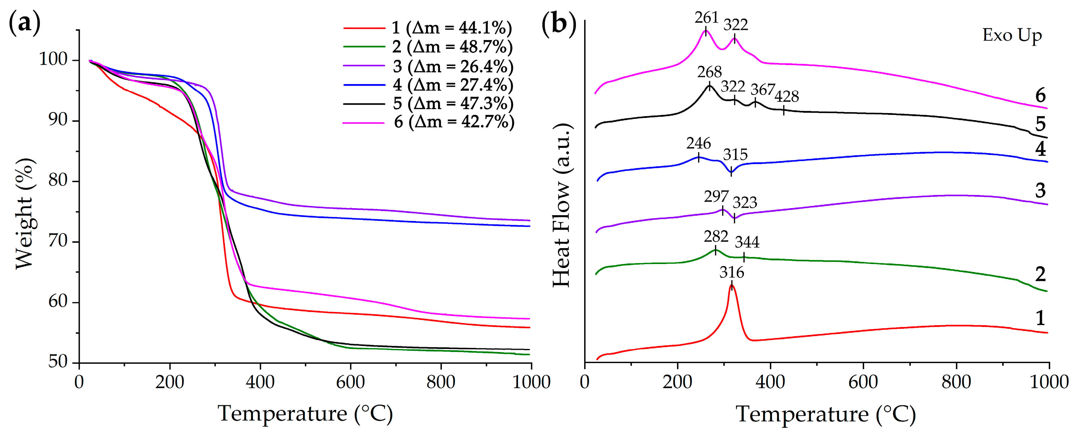
2.1. Examination of Semi-Products and NiO Nanopowders

In this work, in order to establish the influence of reagent concentrations and their quantitative ratio on the semi-products and final products properties, the specified parameters were varied in a sufficiently wide range (Table 1). Thus, the nickel chloride concentration ranged from 0.005 to 0.100 mol/L and triethanolamine concentration ranged between 0.010 and 0.400 mol/L. Thus, the reagent ratios (c(TEA)/c(Ni2+)) were changed in the range of 2–80.
To study the behavior of the obtained semi-products in the temperature range of 25–1000 °C, a synchronous thermal analysis was applied (Figure 1). As can be seen from the thermograms, the powders (Figure 1a) can be divided into 4 groups according to the nature of their thermal transformation and the resulting mass loss: group 1 (samples 2 and 5), group 2 (sample 1), group 3 (sample 6), and group 4 (samples 3 and 4). This grouping of semi-products agrees well with their synthesis conditions. Thus, group 1 powders corresponded to the maximum concentration (0.100 mol/L) of nickel chloride in the reaction system during synthesis. The maximum ratio of triethanolamine and nickel chloride concentrations (c(TEA)/c(Ni2+) = 80) was observed for group 2 (sample 1). In the case of group 3 (sample 6), this ratio (c(TEA)/c(Ni2+) = 16) is significantly lower than in group 2 but at the same time greatly exceeds this parameter with respect to other groups. Group 2 semi-products differ from the others in the lowest triethanolamine concentration in the reaction systems (0.010 and 0.050 for samples 3 and 4, respectively). The above grouping of the samples generally agrees fairly well with the type of DSC curves as well (Figure 1b). Thus, at the first stage of heating (in the interval 25–200 °C) for all samples (except for samples 1 and 3), there is a 1.5–3% weight loss associated with the evaporation of the residual solvent and sorbed atmospheric gases. For samples 1 and 3, the first step of mass loss is more extended in temperature (25–250 °C), and the corresponding Δm values are about 12 and 3%, respectively. The second mass loss step for groups 1, 3, and 4 (except for sample 3), accompanied by exothermic effects, is in the region of 200–300 °C, and the mass loss in this case has a value of 16–18, 8, and 3%, respectively. Furthermore, as the temperature rises above 300 °C, the intensification of mass loss is observed in all samples. For groups 1 and 3, this temperature range is wider (300–400 °C; Δm value of 22–24%) and energy release is observed, whereas in the case of groups 2 and 4, this interval is considerably narrower (300–350 °C, Δm (group 2) = 27%; Δm (group 4) ~ 17%). The mass loss for group 2 is accompanied by an intense exo-effect, whereas the samples of group 4 demonstrate energy absorption that is essentially different from other powders (in particular, the presence of similar endo-effects that may refer to the decomposition of β-Ni(OH)2 to NiO [67]). Such features testify to significant differences in the chemical composition or crystalline structure of the above semi-products. A further increase in temperature leads to a considerable slowing of the mass loss for the samples of groups 2 and 4. For group 1 samples, an ~8% mass loss step is observed in the range of 400–600 °C. For group 3, a step of mass loss (~5%) is visible enough when using a wider temperature range (400–750 °C). The optimal conditions for the additional heat treatment of semi-products (400 °C, 1 h) and for their complete decomposition and nickel (II) oxide crystallization were determined by the analysis results. Thus, the synchronous thermal analysis data for the obtained semi-products indicate a significant influence of the synthesis conditions on their thermal transformation, and probably had an influence on their chemical composition and crystal structure as well.
An X-ray diffraction analysis of the semi-products (Figure 2a) made it possible to determine the significant dependence of the obtained powders’ crystal structures on their synthesis conditions. The X-ray diffraction patterns show that the main component of samples 1 and 2 is α-Ni(OH)2 (JCPDS card #38–0715), and the presence of low-angle basal reflections indicates the layered nature of their crystal structure [68]. In the case of sample 1, there is a reduced crystallinity degree, which may be due to the intercalation of the anions present in the reaction system into the material structure, which leads to the stacking rearrangement of the layered hydroxide unit cell and the increased degree of disorder in the stacked structure. The formation of carbonate ions in the reaction systems during hydrothermal treatment suggests that samples 1 and 2 have the composition of [Ni(OH)2–x(CO3)0.5x·yH2O] (where x = 0.2–0.4, y = 0.6–1.0) (JCPDS card #22–752) [69]. For samples 5 and 6, the main component also has a structure similar to the α-modification of nickel (II) hydroxide. In this case (in contrast to samples 1 and 2), there are no reflexes below 7° of the 2θ angle in the XRD patterns, although a general shift of the (003) plane to a low angle region is also observed, indicating the formation of a layered structure of the material. The reflections in the 2θ range of 16–17° on the XRD patterns of the samples 1, 2, 5, and 6 could be attributed to the admixture of the nickel hydrocarbonate of the composition Ni(HCO3)2 (JCPDS card #15–0782) [70]. Samples 3 and 4 significantly differ from the others in terms of their crystal structure. As can be seen, β-Ni(OH)2 (JCPDS #14–0117) [71] is the major component for these semi-products, and the corresponding major diffraction reflections are located around 18.7°, 33.2°, 38.6°, 52.3°, 59.1°, and 62.8°. It should be noted that at 2θ ~ 20.8°, an additional diffraction peak is also observed, which may be related to the presence of Ni2(CO3)(OH)2 (JCPDS card #35–0501) [70]. Thus, the X-ray diffraction analysis of the semi-products suggests that by reducing the triethanolamine concentration in the reaction system to 0.010–0.050 mol/L with a simultaneous decrease of the c(TEA)/c(Ni2+) ratio to 2, there is a tendency for the formation of β-Ni(OH)2-based powders. A significant increase in the triethanolamine concentration (up to 0.400 mol/L) at a low nickel chloride concentration (0.005 mol/L) leads to the formation of layered nickel (II) hydroxide in α-modification.
Additional heat treatment of the semi-products at 400 °C for 1 h, as can be seen from the corresponding XRD patterns (Figure 2b), leads to their complete decomposition and leads to the formation of the cubic NiO crystal structure (JCPDS card #78–0643, space group Fm-3 m) [72]. Using the obtained data in accordance with the Debye–Scherrer formula, the average size of the coherent scattering region (CSR) for NiO powders was estimated. As a result, it was determined that this parameter value is consistent with the hydrothermal synthesis conditions and thermal analysis data. Thus, the minimum values of CSR corresponded to samples 1 (8 ± 1 nm) and 6 (6 ± 1 nm), for which the c(TEA)/c(Ni2+) ratio was the highest at the stage of intermediates synthesis and the resulting mass loss on the TGA curves had an average value. For samples 2 and 5, the CSR values were the maximum (sample 2: 14 ± 1 nm, sample 5: 19 ± 2 nm), which agrees with the maximum concentration of nickel chloride in the reaction systems (0.100 mol/L) and highest Δm values from the thermal analysis. The group of samples 3 and 4 has an intermediate CSR value (sample 3: 9 ± 1 nm, sample 4: 10 ± 1 nm); this difference also corresponds well with the synthesis conditions of the intermediates (the minimum triethanolamine concentration at the lowest values of the c(TEA)/c(Ni2+)) ratio, their thermal analysis results (the minimum resulting mass loss), and the crystal structure features (on β-Ni(OH)2-based powders).
The determination of functional groups in the obtained semi-products was carried out using FTIR spectroscopy (Figure 3). As can be seen from the spectra for samples 1, 2, 3, and 4, a narrow absorption band with a maximum of about 3650 cm−1 is clearly observed, which is related to the stretching vibration of free hydroxyl groups of nickel hydroxide [73,74]. For samples 5 and 6, this band is less pronounced. A broad absorption band in the 3100–3750 cm−1 region is observed for all intermediates and refers to the stretching vibrations of the bound OH groups. It should be noted that these absorption bands are the most intense for sample 1. For all samples, there is also an absorption band with a maximum of about 1630 cm−1, which refers to the bending vibrations of the OH groups. The spectra of the studied semi-products also show that for all samples there is a complex-form absorption band at 950–1240 cm−1 as well as a narrow band around 912 cm−1 (for samples 1, 2, 5, and 6) related to carbonate ions vibrations [75], which is in good agreement with the XRD results concerning the presence of Ni(HCO3)2 in samples 1, 2, 5, and 6 and Ni2(CO3)(OH)2 in samples 3 and 4. In addition, for samples 3 and 4, these absorption bands are characterized by a lower intensity, which is probably due to the lower carbonate ions content in the above impurity composition and is manifested by a lower Δm value on the corresponding TGA curves. After additional heat treatment of semi-products at 400 °C, there is a complete disappearance of absorption bands related to the functional groups considered above. Thus, the spectrum of NiO powder obtained using sample 2 is provided as an example. In the corresponding spectrum, in addition to the Vaseline oil absorption bands, there is only one band with a maximum at 420 cm−1 that is associated with the Ni–O group stretching vibrations [76].
The NiO powders microstructure after additional heat treatment at 400 °C was studied using scanning electron microscopy (SEM; Figure 4). It can be seen that the obtained powders are agglomerates consisting of differently shaped particles. Thus, in the case of samples 1, 5, and 6 synthesized at a higher triethanolamine concentration (0.400 mol/L), it was found that plate-like structures of slightly distorted shape are present on the surface of the agglomerates. Decreasing the precipitant concentration while maintaining a high nickel chloride concentration (sample 2) results in the formation of a hierarchically organized material consisting of flat, somewhat elongated particles (average size about 50 nm), which form nanosheets that are about 12 nm thick and are ordered at an angle to one another in the form of honeycomb agglomerates. A further decrease in the reagents concentration while maintaining the c(TEA)/c(Ni2+) ratio at 2 probably leads to the degradation of the self-organized structure and formation of individual planar agglomerates whose average size and thickness increase from 150 (sample 4) to 300 nm (sample 3) and from 12 (sample 4) to 45 nm (sample 3), respectively. At the same time, the surface of the observed agglomerates within these two samples are covered by smaller particles whose average size increases from 13 (sample 4) to 25 nm (sample 3).
Transmission electron microscopy (TEM; Figure 5) allowed for a more detailed study of the microstructure features of the obtained oxide nanopowders. The TEM results are generally consistent with the SEM data. Thus, sample 1 obtained in the case of a large excess of the precipitant mainly consists of small particles that are about 10 nm in size and nanosheet fragments with small thicknesses. With a decrease in the nickel chloride concentration in the reaction system while retaining a large amount of triethanolamine (sample 5), a polymodal particle size distribution is observed; there are highly dispersed particles with an average size of about 8 nm, larger faceted particles (about 45 nm), and slightly elongated plate-like structures (about 100 nm long) as observed earlier in the SEM images. In the case of sample 6, the use of TEM allowed for the specification of planar particles observed in the corresponding microphotograph (Figure 4), which apparently consisted of rod-like structures (about 230 nm long) and in turn are organized from smaller particles with a size of about 14 nm. Sample 2, for which SEM data previously indicated a hierarchical organization of the microstructure, according to TEM results consists of lamellar structures (nanosheets) with clear edges on the surface, where small particles of about 15 nm can be observed. In the case of samples 3 and 4, the micrographs show fragments of planar agglomerates consisting of small nanosheets with an average size of 30 (sample 4) to 40 (sample 3) nm, along with highly dispersed particles ranging from 13 (sample 4) to 10 (sample 3) nm. The corresponding histograms clearly show the bimodal particle size distribution for samples 2 and 5 obtained from reaction systems with the highest nickel chloride concentration. As can be seen, the microstructural features (in particular, dispersity) of the obtained NiO powders agree quite well with the CSR values determined by the XRD data.
Based on the microstructure analysis of the obtained NiO nanopowders, to further form the functional ink and subsequent microextrusion printing of the electrode coating of the composition NiO— (CeO2)0.80(Sm2O3)0.20 (NiO—SDC), sample 2 was chosen, which is characterized by the most ordered hierarchically organized morphology.

2.2. Characterization of the Printed NiO—SDC Film

The crystal structure of the printed NiO—SDC composite film was studied using an X-ray diffraction analysis (Figure 6). The corresponding XRD patterns demonstrate that in addition to the intense narrow reflexes related to the substrate, signals from the film components ((CeO2)0.80(Sm2O3)0.20 and NiO) are present as well. The low-intensity character of the reflexes from the investigated planar structure also indirectly confirms its small thickness, and the broadened reflexes testify to the preservation of the high dispersion of components (in particular, for the SDC phase, the average size of the CSR is 8 nm, and the signals from NiO particles largely overlap the substrate background, which complicates the estimation of this parameter). Thus, the XRD analysis of the obtained film surface confirmed its composite structure, the preservation of the crystal lattice type of its constituents, and the absence of impurities from the possible interaction with the substrate material.
The resulting film microstructure was analyzed using SEM (Figure 7). Thus, SE2 and InLens secondary electron detectors were employed to analyze the material topography and component dispersion, respectively. As can be observed from the micrographs, the film consists of uniformly distributed nanospheres (about 250 nm in diameter) related to samarium-doped ceria, as well as nanosheets and smaller particles of nickel (II) oxide. At the same time, (CeO2)0.80(Sm2O3)0.20 nanospheres are covered by a thin shell of NiO particles ranging 20–30 nm, which probably formed during the functional ink preparation by means of components self-organization. It should also be noted that the character of their microstructure in the process of ink preparation, film printing, and additional heat treatment was preserved and corresponds to the used nanopowders. In addition, the formed NiO—SDC composite film has a sufficiently high porosity, which is an important parameter for the anode components to ensure their efficiency. The study of the material surface also confirmed the absence of any impurities that differ from the main components in terms of dispersity or particle shape.
The AFM results (Figure 8) for the investigated composite film agree well with the SEM data. From the topographic images (Figure 8a,b), it was determined that the surface of the material has an arithmetic mean profile deviation (Ra) of about 88 nm and consists of nanoparticles of different shapes and sizes. In particular, spherical particles with diameters in the range of 170–220 nm are clearly visible along with particles of more elongated shape. The length of these particles is mostly close to the diameter of the spheres, although submicron-size formations (up to 600 nm) are also found. From the analysis of the microstructure of powders used for the functional ink preparation, it follows that the nanospheres belong to the oxide composition (CeO2)0.80(Sm2O3)0.20, while the elongated particles belong to the nickel oxide nanosheets. The different chemical nature of these particles is confirmed by the KPFM data (Figure 8c). The resulting surface potential distribution map shows that nanospheres correspond to darker areas, while the more elongated formations correspond to lighter areas. The difference in the potential values in this case reaches 150 mV and, overall, the contrast between the different potentials of the film sections is visible enough on the map. At the same time, the capacitance gradient map of the capacitor “probe tip-sample microregion” (Figure 8d), obtained by semi-contact SCM, does not show a significant contrast-probably, it mainly reflects the depleted zones at the boundaries between particles.
The work function value of the material surface was determined based on the KPFM results. For samarium-doped ceria nanospheres, the work function value was 4.61 eV, and for NiO particles it was 4.5 eV. This parameter of (CeO2)0.80(Sm2O3)0.20 oxide is slightly higher than the value (4.44 eV) we obtained for the material of the same composition synthesized under different conditions in our previous research [64]. This, as well as the microstructural differences, is presumably explained by the peculiarities of the synthesis conditions. Probably, the material formed under these conditions is characterized by a lower concentration of defects (primarily oxygen vacancies), which results in an increased work function value. The work function for NiO also differs from the previously obtained value for a similar hydrothermal synthesis product in the presence of triethanolamine (but at a lower temperature); in Ref. [77], we obtained a value of 4.75 eV. NiO is known to be a p-type semiconductor because of the cationic vacancies it contains [78]. Such vacancies can be considered as “acceptors” of electrons and, as a consequence, as their concentration increases, the Fermi level decreases and the work function value grows. Accordingly, it can be assumed that the higher-temperature synthesis in our case promotes the formation of a more stoichiometric NiO oxide, which leads to a lower work function value. The formed composite film thickness was also determined by the AFM analysis, where it was determined to be 5 μm.
The conductivity of the NiO—SDC composite film was evaluated using four-probe DC measurements in the temperature range of 300–650 °C. It is known that in the case of such materials, both components influence the final conductivity value, with the nickel oxide determining the electronic conductivity and the cerium dioxide-based solid solution influencing the ionic conductivity [79]. It can be seen (Figure 9) that the obtained dependence is linear in the entirety of the range under consideration, and the conductivity value increases by several orders of magnitude (from 7.5–10−4 to 0.3 S/cm). These conductivity values generally correspond to those obtained for similar anode materials; however, they can be increased by an additional high-temperature treatment [79,80]. The activation energy of conductivity was calculated using the following formula:
σ = A / T · e E a k T ,
where A is the pre-exponential factor, T is the absolute temperature, k is the Boltzmann constant, and Ea is the activation energy of conductivity.
In our case, the activation energy for the 500–650 °C region, which is of the greatest interest in the context of the intermediate-temperature SOFCs operating temperatures, was 0.42 eV, which also agrees with the data for NiO—SDC composites [81].

3. Materials and Methods

3.1. Materials

NiCl2·6H2O (>98%, RUSHIM, Moscow, Russia), (triethanolamine (C6H15NO3, 99%, Chimmed, Moscow, Russia), α-terpineol (>97%, Vekton, St. Petersburg, Russia), and ethylcellulose (48.0–49.5% (w/w) ethoxyl basis, Sigma Aldrich, St. Louis, MO, USA) were used in this work without further purification.

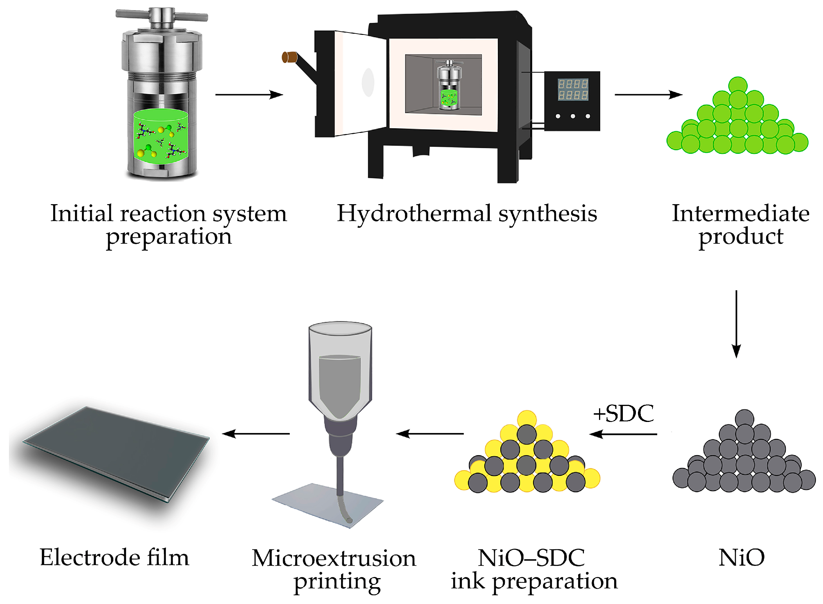
3.2. Hydrothermal Synthesis of NiO Nanopowders

The formation of NiO nanopowders was carried out using the hydrothermal method. Thus, at the first stage, the reaction systems representing 40 mL of aqueous solutions with different concentration ratios of nickel chloride and triethanolamine (Table 1) were prepared and subjected to hydrothermal treatment in a 100 mL Teflon-lined stainless-steel autoclave at 200 °C for 1 h (heating rate of 1.5 °C/min). After the natural cooling of the systems, the solid phase particles that formed during the synthesis were separated from the mother liquors and washed with distilled water using a cyclic centrifugation technique; the semi-products that were obtained were further dried (100 °C, 3 h) and additionally heat-treated (400 °C, 1 h) for their decomposition and nickel (II) oxide crystallization.

3.3. Microextrusion Printing of NiO—SDC Electrode Film

In order to further develop the NiO—(CeO2)0.80(Sm2O3)0.20 composite electrode film, the corresponding functional inks were prepared based on the obtained nanopowder of nickel oxide (sample 2) and previously synthesized oxide of (CeO2)0.80(Sm2O3)0.20 composition [82] in a 50:50 wt.% ratio, to which α-terpineol was added as a solvent (ethylcellulose, 20 wt.% was used as a binder). The total mass fraction of oxide particles in the composition of the obtained composite functional ink was 15%. The features of the microextrusion printing technique used for oxide films fabrication were described in our previous works [63,64]. In the current study, the NiO—SDC film (lateral dimensions 6 × 8 mm) was deposited on the surface of a polycrystalline Al2O3 substrate (dimensions 0.5 × 6 × 8 mm, Ra = 100 nm). After the printing process was completed, a step-drying of the material was conducted in the temperature range of 40–60 °C (5 h), and additional heat treatment (400 °C, 1 h) was performed to remove residual solvent and decompose the organic components in the functional ink. For electrophysical measurements, four parallel Ag strip electrodes were also applied to the surface of the formed composite film using microextrusion printing. The technological stages of NiO nanopowders formation and the corresponding coating printing are shown in Figure 10.

3.4. Instrumentation

The semi-products obtained during the hydrothermal synthesis and subsequent drying were characterized using a simultaneous thermal analysis (TGA/DSC) with an SDT Q-600 thermal analyzer (TA Instruments, New Castle, DE, USA). Controlled heating was carried out in the temperature range of 25–1000 °C at a speed of 10 °/min, and the air flow rate was 250 mL/min. The samples weight was varied in the range of 10–15 mg.
The Fourier-transform infrared transmission spectra of the powders under study were recorded on an InfraLUM FT-08 FTIR spectrometer (Lumex, St. Petersburg, Russia) in the wavenumber interval of 350–4000 cm−1 (signal accumulation time 15 s, resolution 1 cm−1). For this purpose, suspensions of the corresponding samples were prepared in Vaseline oil and placed between two potassium bromide glasses.
The crystal structure of the powders and composite film were studied using an X-ray diffraction analysis on a Bruker D8 Advance diffractometer (CuKα radiation, λ = 1.5418 Å, Ni-filter, E = 40 keV, I = 40 mA, 2θ angle range 5–80°, resolution—0.02°, signal accumulation time at a single point was 0.3 s). To estimate the average CSR size of NiO powders, the Debye–Scherrer equation was used:
D = k × λ β × c o s θ ,
where D, λ, k, β, and θ are the CSR size, X-ray wavelength, Scherrer’s constant, full width at half maximum, and diffraction angle, respectively.
The microstructure features of the powders were studied using scanning electron microscopy (Carl Zeiss NVision-40, Carl Zeiss, Inc., Oberkochen, Germany) and transmission electron microscopy (JEOL JEM-1011, JEOL Ltd., Akishima, Tokyo, Japan). The microstructure character of the resulting composite film was also studied using SEM. Additional analysis of the morphology and local electrophysical properties of the printed NiO—SDC film was performed using atomic force microscopy. For this purpose, a Solver Pro-M scanning probe microscope (NT-MDT, Zelenograd, Russia) and ETALON HA-HR probes (ScanSens, Bremen, Germany) with tungsten carbide-based conductive coating (resonance frequency ~213 kHz, tip rounding radius <35 nm) were used in semicontact AFM, Kelvin probe force microscopy, and scanning capacitance microscopy modes. All measurements were performed in air. The electronic work functions of different sections of the material were determined by subtracting the contact potential between the probe and the film from the previously known work function value of the probe tip (4.68 eV).
The electrical conductivity of the printed anode composite film was measured using a four-probe method on a direct current in the temperature range of 300–650 °C in air using a P-45X potentiostat/galvanostat (Electrochemical Instruments, Chernogolovka, Russia). The total conductivity of the sample was calculated by the formula:
σ = I × L U × S ,
where I is the current flowing through the sample (A); L is the distance between the two internal electrodes (cm); U is the voltage between the two internal electrodes (V); and S is the cross-sectional area of the test material (cm2).

4. Conclusions

The hydrothermal synthesis of nickel oxide in the presence of triethanolamine was studied, and the dependencies between the synthesis conditions, thermal behavior, crystal structure features, phase composition, and microstructure of the semi-products and target oxide nanopowders were established. It was shown that upon a decrease in the triethanolamine concentration in the reaction system down to 0.010–0.050 mol/L and a simultaneous decrease in the c(TEA)/c(Ni2+) ratio to 2, a formation of β-Ni(OH)2-based powders tends to occur. A significant increase in the triethanolamine concentration (up to 0.400 mol/L) at a low-nickel chloride concentration (0.005 mol/L) leads to the formation of layered nickel (II) hydroxide in α-modification. For intermediates whose main component is α-Ni(OH)2, nickel hydrocarbonate having the Ni(HCO3)2 composition was found to be a crystalline impurity. In the case where the main component is β-Ni(OH)2, it is accompanied by a Ni2(CO3)(OH)2 impurity. It was determined that an additional heat treatment of the semi-products at 400 °C for 1 h leads to their complete decomposition and formation of a cubic NiO crystal structure. It was found that the minimum values of the CSR size correspond to the NiO powders (6–8 nm) for the stage of semi-product synthesis at which the c(TEA)/c(Ni2+) ratios were the highest and the final mass loss on the TGA curves had an average value. For the samples obtained at the maximum nickel chloride concentration in the reaction systems (0.100 mol/L), the CSR values were maximum (14–19 nm), which was also evident in the highest Δm values from the thermal analysis results. Using one of the obtained NiO nanopowders and the previously synthesized nanospheres of the (CeO2)0.80(Sm2O3)0.20 composition, functional ink was obtained, and a NiO—SDC composite anode film was formed by using microextrusion printing. It was demonstrated that the crystal structure, dispersity, and microstructure character of the obtained material correspond to the initial nanopowders. It was also determined that the material has a sufficiently high porosity, which is an important parameter for the anode components in order to ensure their efficiency. Using the AFM analysis, it was found that the film thickness is 5 μm. The local electrophysical properties of the composite film were studied using KPFM and SCM techniques. In addition, the value of its conductivity was evaluated by the four-probe method with a direct current and in the temperature range of 300–650 °C. As a result, it was found that the obtained temperature dependence is linear in the entirety of the considered range, and the conductivity value increases by several orders of magnitude (from 7.5–10−4 to 0.3 S/cm). The activation energy for the 500–650 °C region, which is of the greatest interest in the context of intermediate-temperature SOFCs operating temperatures, was 0.42 eV, which also agrees with the data for NiO—SDC composites.

Author Contributions

Conceptualization, N.P.S. and T.L.S.; investigation, D.A.D., T.L.S., P.Y.G., I.A.V., E.P.S. and N.P.S.; writing—original draft preparation, D.A.D., T.L.S., P.Y.G., N.P.S. and N.T.K.; writing—review and editing, T.L.S., I.A.V., N.P.S., E.P.S. and N.T.K.; visualization, D.A.D., T.L.S., P.Y.G. and N.P.S.; supervision, N.P.S., I.A.V., E.P.S. and N.T.K.; funding acquisition, T.L.S. and I.A.V. All authors have read and agreed to the published version of the manuscript.

Funding

This work was supported by the Russian Science Foundation under Project No. 21-73-00288, https://rscf.ru/en/project/21-73-00288/, accessed on 4 March 2023 (synthesis of research objects and their characterization) and by the Ministry of Science and Higher Education of the Russian Federation (State Contract No. 075-03-2023-106, project identifier 0714-2020-0007) (in the part of the oxide film formation and FTIR spectroscopy studies).

Institutional Review Board Statement

Not applicable.

Informed Consent Statement

Not applicable.

Data Availability Statement

The data presented in this study are available in this article.

Conflicts of Interest

The authors declare no conflict of interest.

References

  1. Azam, A.; Rafiq, M.; Shafique, M.; Yuan, J. Towards Achieving Environmental Sustainability: The Role of Nuclear Energy, Renewable Energy, and ICT in the Top-Five Carbon Emitting Countries. Front. Energy Res. 2022, 9, 804706. [Google Scholar] [CrossRef]
  2. Armaroli, N.; Balzani, V. The Future of Energy Supply: Challenges and Opportunities. Angew. Chem. Int. Ed. 2007, 46, 52–66. [Google Scholar] [CrossRef] [PubMed]
  3. Gielen, D.; Gorini, R.; Wagner, N.; Leme, R.; Gutierrez, L.; Prakash, G.; Asmelash, E.; Janeiro, L.; Gallina, G.; Vale, G.; et al. IRENA Global Energy Transformation: A Roadmap to 2050; Institution of Gas Engineers & Managers (IGEM): Derby, UK, 2019; ISBN 978-92-9260-121-8. [Google Scholar]
  4. Simonenko, T.L.; Kalinina, M.V.; Simonenko, N.P.; Simonenko, E.P.; Glumov, O.V.; Mel’nikova, N.A.; Murin, I.V.; Shichalin, O.O.; Papynov, E.K.; Shilova, O.A.; et al. Synthesis of BaCe0.9-xZrxY0.1O3-δ nanopowders and the study of proton conductors fabricated on their basis by low-temperature spark plasma sintering. Int. J. Hydrogen Energy 2019, 44, 20345–20354. [Google Scholar] [CrossRef]
  5. Kuterbekov, K.A.; Nikonov, A.V.; Bekmyrza, K.Z.; Pavzderin, N.B.; Kabyshev, A.M.; Kubenova, M.M.; Kabdrakhimova, G.D.; Aidarbekov, N. Classification of Solid Oxide Fuel Cells. Nanomaterials 2022, 12, 1059. [Google Scholar] [CrossRef]
  6. Li, N.; Liu, B.; Jia, L.; Yan, D.; Li, J. Liquid biofuels for solid oxide fuel cells: A review. J. Power Sources 2023, 556, 232437. [Google Scholar] [CrossRef]
  7. Liu, F.; Diercks, D.; Hussain, A.M.; Dale, N.; Furuya, Y.; Miura, Y.; Fukuyama, Y.; Duan, C. Nanocomposite Catalyst for High-Performance and Durable Intermediate-Temperature Methane-Fueled Metal-Supported Solid Oxide Fuel Cells. ACS Appl. Mater. Interfaces 2022, 14, 53840–53849. [Google Scholar] [CrossRef]
  8. Liu, F.; Duan, C. Direct-Hydrocarbon Proton-Conducting Solid Oxide Fuel Cells. Sustainability 2021, 13, 4736. [Google Scholar] [CrossRef]
  9. Dicks, A.L.; Rand, D.A.J. Fuel Cell Systems Explained; Wiley: Hoboken, NJ, USA, 2018; ISBN 9781118613528. [Google Scholar]
  10. Grigor’yants, R.R.; Zalkind, V.I.; Ivanov, P.P.; Lyalin, D.A.; Miroshnichenko, V.I. Thermodynamic model and analysis of hybrid power installations built around solid-oxide fuel cells and gas-turbine units. Therm. Eng. 2008, 55, 790–794. [Google Scholar] [CrossRef]
  11. Henke, M.; Willich, C.; Steilen, M.; Kallo, J.; Friedrich, K.A. Solid Oxide Fuel Cell—Gas Turbine Hybrid Power Plant. ECS Trans. 2013, 57, 67–72. [Google Scholar] [CrossRef] [Green Version]
  12. Dwivedi, S. Solid oxide fuel cell: Materials for anode, cathode and electrolyte. Int. J. Hydrogen Energy 2020, 45, 23988–24013. [Google Scholar] [CrossRef]
  13. Hussain, S.; Yangping, L. Review of solid oxide fuel cell materials: Cathode, anode, and electrolyte. Energy Transit. 2020, 4, 113–126. [Google Scholar] [CrossRef]
  14. Tian, D.; Liu, W.; Chen, Y.; Yu, W.; Yu, L.; Lin, B. A robust NiO–Sm0.2Ce0.8O1.9 anode for direct-methane solid oxide fuel cell. Mater. Res. Bull. 2015, 71, 1–6. [Google Scholar] [CrossRef] [Green Version]
  15. Namioka, T.; Naruse, T.; Yamane, R. Behavior and mechanisms of Ni/ScSZ cermet anode deterioration by trace tar in wood gas in a solid oxide fuel cell. Int. J. Hydrogen Energy 2011, 36, 5581–5588. [Google Scholar] [CrossRef]
  16. Fashalameh, K.M.; Sadeghian, Z.; Ebrahimi, R. A high-performance planar anode-supported solid oxide fuel cell with hierarchical porous structure through slurry-based three-dimensional printing. J. Alloys Compd. 2022, 916, 165406. [Google Scholar] [CrossRef]
  17. Rafique, M.; Nawaz, H.; Shahid Rafique, M.; Bilal Tahir, M.; Nabi, G.; Khalid, N.R. Material and method selection for efficient solid oxide fuel cell anode: Recent advancements and reviews. Int. J. Energy Res. 2019, 43, 2423–2446. [Google Scholar] [CrossRef]
  18. Shabri, H.A.; Othman, M.H.D.; Mohamed, M.A.; Kurniawan, T.A.; Jamil, S.M. Recent progress in metal-ceramic anode of solid oxide fuel cell for direct hydrocarbon fuel utilization: A review. Fuel Process. Technol. 2021, 212, 106626. [Google Scholar] [CrossRef]
  19. Toscani, L.M.; Bellora, M.S.; Huck-Iriart, C.; Soldati, A.L.; Sacanell, J.; Martins, T.S.; Craievich, A.F.; Fantini, M.C.A.; Larrondo, S.A.; Lamas, D.G. NiO/CeO2-Sm2O3 nanocomposites for partial oxidation of methane: In-situ experiments by dispersive X-ray absorption spectroscopy. Appl. Catal. A Gen. 2021, 626, 118357. [Google Scholar] [CrossRef]
  20. Genoveva Zimicz, M.; Reznik, B.A.; Larrondo, S.A. Conversion of biogas to synthesis gas over NiO/CeO2–Sm2O3 catalysts. Fuel 2015, 149, 95–99. [Google Scholar] [CrossRef]
  21. Gan, T.; Song, H.; Fan, X.; Liu, Y.; Liu, S.; Zhao, Y.; Li, Y. A rational design of highly active and coke-resistant anode for methanol-fueled solid oxide fuel cells with Sn doped Ni-Ce0.8Sm0.2O2−δ. Chem. Eng. J. 2023, 455, 140692. [Google Scholar] [CrossRef]
  22. Sun, M.H.; Huang, S.Z.; Chen, L.H.; Li, Y.; Yang, X.Y.; Yuan, Z.Y.; Su, B.L. Applications of hierarchically structured porous materials from energy storage and conversion, catalysis, photocatalysis, adsorption, separation, and sensing to biomedicine. Chem. Soc. Rev. 2016, 45, 3479–3563. [Google Scholar] [CrossRef] [PubMed]
  23. Song, X.; Gao, L. Facile Synthesis and Hierarchical Assembly of Hollow Nickel Oxide Architectures Bearing Enhanced Photocatalytic Properties. J. Phys. Chem. C 2008, 112, 15299–15305. [Google Scholar] [CrossRef]
  24. Yuan, Y.F.; Xia, X.H.; Wu, J.B.; Yang, J.L.; Chen, Y.B.; Guo, S.Y. Hierarchically ordered porous nickel oxide array film with enhanced electrochemical properties for lithium ion batteries. Electrochem. Commun. 2010, 12, 890–893. [Google Scholar] [CrossRef]
  25. Yao, M.; Hu, Z.; Xu, Z.; Liu, Y.; Liu, P.; Zhang, Q. High-performance electrode materials of hierarchical mesoporous nickel oxide ultrathin nanosheets derived from self-assembled scroll-like α-nickel hydroxide. J. Power Sources 2015, 273, 914–922. [Google Scholar] [CrossRef]
  26. Feng, X.; Huang, Y.; Li, C.; Li, Y.; Chen, C.; Liu, P. Raspberry-like Ni/NiO/CoO/Mn3O4 hierarchical structures as novel electrode material for high-performance all-solid-state asymmetric supercapacitors. Ceram. Int. 2019, 45, 18273–18280. [Google Scholar] [CrossRef]
  27. Cao, C.Y.; Guo, W.; Cui, Z.M.; Song, W.G.; Cai, W. Microwave-assisted gas/liquid interfacial synthesis of flowerlike NiO hollow nanosphere precursors and their application as supercapacitor electrodes. J. Mater. Chem. 2011, 21, 3204–3209. [Google Scholar] [CrossRef]
  28. Wahyuono, R.A.; Dellith, A.; Schmidt, C.; Dellith, J.; Ignaszak, A.; Seyring, M.; Rettenmayr, M.; Fize, J.; Artero, V.; Chavarot-Kerlidou, M.; et al. Structure of Ni(OH)2 intermediates determines the efficiency of NiO-based photocathodes-a case study using novel mesoporous NiO nanostars. RSC Adv. 2019, 9, 39422–39433. [Google Scholar] [CrossRef] [Green Version]
  29. Sheokand, S.; Kumar, P.; Jabeen, S.; Samra, K.S. 3D highly porous microspherical morphology of NiO nanoparticles for supercapacitor application. J. Solid State Electrochem. 2023, 27, 727–738. [Google Scholar] [CrossRef]
  30. Zhang, W.X.; Zhang, J.H.; Guo, J.Q.; He, C.; Wen, J.R. NiS2 nanospheres coated by nitrogen-doped carbon for enhanced sodium storage performance. J. Alloys Compd. 2023, 937, 168379. [Google Scholar] [CrossRef]
  31. Simonenko, T.L.; Bocharova, V.A.; Gorobtsov, P.Y.; Simonenko, N.P.; Muradova, A.G.; Simonenko, E.P.; Sevastyanov, V.G.; Kuznetsov, N.T. Formation of Hierarchical NiO Coatings on the Surface of Al2O3 Substrates under Hydrothermal Conditions. Russ. J. Inorg. Chem. 2020, 65, 1292–1297. [Google Scholar] [CrossRef]
  32. Fan, J.; Lu, J.; Sha, Z.; Zuo, W.; Fei, X.; Zhu, M. Conformally anchoring nanocatalyst onto quartz fibers enables versatile microreactor platforms for continuous-flow catalysis. Sci. China Chem. 2021, 64, 1596–1604. [Google Scholar] [CrossRef]
  33. Zhang, Y.; Zhao, J.; Kang, X.; Chen, G.; Li, Y. Synthesis the flower-like N-C/NiO nanocomposites by one-pot hydrothermal method as efficient electrocatalyst for methanol oxidation in alkaline electrolyte. Colloids Surf. A Physicochem. Eng. Asp. 2021, 629, 127466. [Google Scholar] [CrossRef]
  34. Wan, X.; Yuan, M.; Tie, S.; Lan, S. Effects of catalyst characters on the photocatalytic activity and process of NiO nanoparticles in the degradation of methylene blue. Appl. Surf. Sci. 2013, 277, 40–46. [Google Scholar] [CrossRef]
  35. Madhura, T.R.; Kumar, G.G.; Ramaraj, R. Reduced graphene oxide supported 2D-NiO nanosheets modified electrode for urea detection. J. Solid State Electrochem. 2020, 24, 3073–3081. [Google Scholar] [CrossRef]
  36. Manibalan, G.; Govindaraj, Y.; Yesuraj, J.; Kuppusami, P.; Murugadoss, G.; Murugavel, R.; Rajesh Kumar, M. Facile synthesis of NiO@Ni(OH)2-α-MoO3 nanocomposite for enhanced solid-state symmetric supercapacitor application. J. Colloid Interface Sci. 2021, 585, 505–518. [Google Scholar] [CrossRef] [PubMed]
  37. Jian, J.; Kou, X.; Wang, H.; Chang, L.; Zhang, L.; Gao, S.; Xu, Y.; Yuan, H. Fascinating Tin Effects on the Enhanced and Large-Current-Density Water Splitting Performance of Sn–Ni(OH)2. ACS Appl. Mater. Interfaces 2021, 13, 42861–42869. [Google Scholar] [CrossRef] [PubMed]
  38. Singh, J.; Lee, S.; Kim, S.; Singh, S.P.; Kim, J.; Rai, A.K. Fabrication of 1D mesoporous NiO nano-rods as high capacity and long-life anode material for lithium ion batteries. J. Alloys Compd. 2021, 850, 156755. [Google Scholar] [CrossRef]
  39. Chung, Y.; Park, H.; Lee, E.; Kim, S.-H.; Kim, D.-J. Communication—Gas Sensing Behaviors of Electrophoretically Deposited Nickel Oxide Films from Morphologically Tailored Particles. J. Electrochem. Soc. 2016, 163, B624–B626. [Google Scholar] [CrossRef]
  40. Baharuddin, N.A.; Abdul Rahman, N.F.; Abdul Rahman, H.; Somalu, M.R.; Azmi, M.A.; Raharjo, J. Fabrication of high-quality electrode films for solid oxide fuel cell by screen printing: A review on important processing parameters. Int. J. Energy Res. 2020, 44, 8296–8313. [Google Scholar] [CrossRef]
  41. Hong, G.; Kim, T.W.; Kwak, M.J.; Song, J.; Choi, Y.; Woo, S.-K.; Han, M.H.; Cho, C.H.; Kim, S.-D. Composite electrodes of Ti-doped SrFeO3-δ and LSGMZ electrolytes as both the anode and cathode in symmetric solid oxide fuel cells. J. Alloys Compd. 2020, 846, 156154. [Google Scholar] [CrossRef]
  42. Hanif, M.B.; Gao, J.-T.; Shaheen, K.; Wang, Y.-P.; Yasir, M.; Zhang, S.-L.; Li, C.-J.; Li, C.-X. Performance evaluation of highly active and novel La0.7Sr0.3Ti0.1Fe0.6Ni0.3O3-δ material both as cathode and anode for intermediate-temperature symmetrical solid oxide fuel cell. J. Power Sources 2020, 472, 228498. [Google Scholar] [CrossRef]
  43. Lin, J.; Li, H.; Wang, W.; Qiu, P.; Tao, G.; Huang, K.; Chen, F. Atmospheric plasma spraying to fabricate metal-supported solid oxide fuel cells with open-channel porous metal support. J. Am. Ceram. Soc. 2023, 106, 68–78. [Google Scholar] [CrossRef]
  44. Won, B.-R.; Kim, Y.H.; Jo, S.; Myung, J. Highly flexible solid oxide fuel cells using phase-controlled electrolyte support. J. Eur. Ceram. Soc. 2022, 42, 5813–5819. [Google Scholar] [CrossRef]
  45. Zhu, J.; Pérez, C.R.; Oh, T.-S.; Küngas, R.; Vohs, J.M.; Bonnell, D.A.; Nonnenmann, S.S. Probing local electrochemical activity within yttria-stabilized-zirconia via in situ high-temperature atomic force microscopy. J. Mater. Res. 2015, 30, 357–363. [Google Scholar] [CrossRef]
  46. Ding, D.; Li, X.; Lai, S.Y.; Gerdes, K.; Liu, M. Enhancing SOFC cathode performance by surface modification through infiltration. Energy Environ. Sci. 2014, 7, 552. [Google Scholar] [CrossRef]
  47. Liu, L.; Kim, G.-Y.; Chandra, A. Fabrication of solid oxide fuel cell anode electrode by spray pyrolysis. J. Power Sources 2010, 195, 7046–7053. [Google Scholar] [CrossRef]
  48. dos Santos-Gómez, L.; Zamudio-García, J.; Porras-Vázquez, J.M.; Losilla, E.R.; Marrero-López, D. Recent progress in nanostructured electrodes for solid oxide fuel cells deposited by spray pyrolysis. J. Power Sources 2021, 507, 230277. [Google Scholar] [CrossRef]
  49. Lee, Y.H.; Ren, H.; Wu, E.A.; Fullerton, E.E.; Meng, Y.S.; Minh, N.Q. All-Sputtered, Superior Power Density Thin-Film Solid Oxide Fuel Cells with a Novel Nanofibrous Ceramic Cathode. Nano Lett. 2020, 20, 2943–2949. [Google Scholar] [CrossRef]
  50. Rezugina, E.; Thomann, A.L.; Hidalgo, H.; Brault, P.; Dolique, V.; Tessier, Y. Ni-YSZ films deposited by reactive magnetron sputtering for SOFC applications. Surf. Coat. Technol. 2010, 204, 2376–2380. [Google Scholar] [CrossRef] [Green Version]
  51. Simonenko, E.P.; Mokrushin, A.S.; Simonenko, N.P.; Voronov, V.A.; Kim, V.P.; Tkachev, S.V.; Gubin, S.P.; Sevastyanov, V.G.; Kuznetsov, N.T. Ink-jet printing of a TiO2–10%ZrO2 thin film for oxygen detection using a solution of metal alkoxoacetylacetonates. Thin Solid Films 2019, 670, 46–53. [Google Scholar] [CrossRef]
  52. Qin, F.; Liu, C.; Wu, W.; Peng, W.; Huo, S.; Ye, J.; Gu, S. Inkjet Printed Quantum Dots Color Conversion Layers for Full-Color Micro-LED Displays. Electron. Mater. Lett. 2023, 19, 19–28. [Google Scholar] [CrossRef]
  53. Sajedi-Moghaddam, A.; Gholami, M.; Naseri, N. Inkjet Printing of MnO2 Nanoflowers on Surface-Modified A4 Paper for Flexible All-Solid-State Microsupercapacitors. ACS Appl. Mater. Interfaces 2023, 15, 3894–3903. [Google Scholar] [CrossRef] [PubMed]
  54. Ha, J.; Yoo, H.; Seo, J.; Yoon, J.; Hong, Y. Photoresponse Analysis of All-Inkjet-Printed Single-Walled Carbon Nanotube Thin-Film Transistors for Flexible Light-Insensitive Transparent Circuit Applications. ACS Appl. Mater. Interfaces 2023, 15, 3192–3201. [Google Scholar] [CrossRef] [PubMed]
  55. Volkov, I.A.; Simonenko, N.P.; Efimov, A.A.; Simonenko, T.L.; Vlasov, I.S.; Borisov, V.I.; Arsenov, P.V.; Lebedinskii, Y.Y.; Markeev, A.M.; Lizunova, A.A.; et al. Platinum Based Nanoparticles Produced by a Pulsed Spark Discharge as a Promising Material for Gas Sensors. Appl. Sci. 2021, 11, 526. [Google Scholar] [CrossRef]
  56. Gamba, L.; Johnson, Z.T.; Atterberg, J.; Diaz-Arauzo, S.; Downing, J.R.; Claussen, J.C.; Hersam, M.C.; Secor, E.B. Systematic Design of a Graphene Ink Formulation for Aerosol Jet Printing. ACS Appl. Mater. Interfaces 2023, 15, 3325–3335. [Google Scholar] [CrossRef]
  57. Zhou, X.; Zhang, L.; Wang, Y.; Zhao, S.; Zhou, Y.; Guo, Y.; Wang, Y.; Liang, J.; Chen, H. Aerosol Jet Printing of Multi-Dimensional OECT Force Sensor with High Sensitivity and Large Measuring Range. Adv. Mater. Technol. 2023, 2201272. [Google Scholar] [CrossRef]
  58. Zuo, Y.; Yu, Y.; Feng, J.; Zuo, C. Ultrathin Al–air batteries by reducing the thickness of solid electrolyte using aerosol jet printing. Sci. Rep. 2022, 12, 9801. [Google Scholar] [CrossRef]
  59. Zang, Z.; Tang, X.; Liu, X.; Lei, X.; Chen, W. Fabrication of high quality and low cost microlenses on a glass substrate by direct printing technique. Appl. Opt. 2014, 53, 7868. [Google Scholar] [CrossRef]
  60. Fragua, D.M.; Abargues, R.; Rodriguez-Canto, P.J.; Sanchez-Royo, J.F.; Agouram, S.; Martinez-Pastor, J.P. Au-ZnO Nanocomposite Films for Plasmonic Photocatalysis. Adv. Mater. Interfaces 2015, 2, 1500156. [Google Scholar] [CrossRef]
  61. Simonenko, T.L.; Simonenko, N.P.; Topalova, Y.P.; Gorobtsov, P.Y.; Simonenko, E.P.; Kuznetsov, N.T. Synthesis of Nanoscale Co3O4 Spinel and Its Application to Form Miniature Planar Structures by Microplotter Printing. Russ. J. Inorg. Chem. 2022, 67, 1939–1947. [Google Scholar] [CrossRef]
  62. Seo, H.; Nishi, T.; Kishimoto, M.; Ding, C.; Iwai, H.; Saito, M.; Yoshida, H. Study of Microextrusion Printing for Enlarging Electrode–Electrolyte Interfacial Area in Anode-Supported SOFCs. ECS Trans. 2019, 91, 1923–1931. [Google Scholar] [CrossRef]
  63. Mokrushin, A.S.; Simonenko, T.L.; Simonenko, N.P.; Gorobtsov, P.Y.; Bocharova, V.A.; Kozodaev, M.G.; Markeev, A.M.; Lizunova, A.A.; Volkov, I.A.; Simonenko, E.P.; et al. Microextrusion printing of gas-sensitive planar anisotropic NiO nanostructures and their surface modification in an H2S atmosphere. Appl. Surf. Sci. 2022, 578, 151984. [Google Scholar] [CrossRef]
  64. Simonenko, T.L.; Simonenko, N.P.; Gorobtsov, P.Y.; Klyuev, A.L.; Grafov, O.Y.; Ivanova, T.M.; Simonenko, E.P.; Sevastyanov, V.G.; Kuznetsov, N.T. Hydrothermally synthesized hierarchical Ce1-xSmxO2-δ oxides for additive manufacturing of planar solid electrolytes. Ceram. Int. 2022, 48, 22401–22410. [Google Scholar] [CrossRef]
  65. Liu, S.; Cao, R.; Wu, J.; Guan, L.; Li, M.; Liu, J.; Tian, J. Directly writing barrier-free patterned biosensors and bioassays on paper for low-cost diagnostics. Sens. Actuators B Chem. 2019, 285, 529–535. [Google Scholar] [CrossRef]
  66. Simonenko, T.L.; Simonenko, N.P.; Gorobtsov, P.Y.; Pozharnitskaya, V.M.; Simonenko, E.P.; Glumov, O.V.; Melnikova, N.A.; Sevastyanov, V.G.; Kuznetsov, N.T. Pen Plotter Printing of MnOx Thin Films Using Manganese Alkoxoacetylacetonate. Russ. J. Inorg. Chem. 2021, 66, 1416–1424. [Google Scholar] [CrossRef]
  67. Liang, Z.-H.; Zhu, Y.-J.; Hu, X.-L. β-Nickel Hydroxide Nanosheets and Their Thermal Decomposition to Nickel Oxide Nanosheets. J. Phys. Chem. B 2004, 108, 3488–3491. [Google Scholar] [CrossRef]
  68. Rana, P.; Jeevanandam, P. Synthesis of NiO Nanoparticles via Calcination of Surfactant Intercalated Layered Nickel Hydroxides and their Application as Adsorbent. J. Clust. Sci. 2022, 34, 517–533. [Google Scholar] [CrossRef]
  69. Xu, L.; Ding, Y.-S.; Chen, C.-H.; Zhao, L.; Rimkus, C.; Joesten, R.; Suib, S.L. 3D Flowerlike α-Nickel Hydroxide with Enhanced Electrochemical Activity Synthesized by Microwave-Assisted Hydrothermal Method. Chem. Mater. 2008, 20, 308–316. [Google Scholar] [CrossRef]
  70. Lee, D.; Shinde, N.; Ding, J.C.; Fu, J.; Sahoo, R.K.; Lee, H.W.; Yun, J.M.; Shin, H.-C.; Kim, K.H. Improvement of electrical performance by surface structure of Ni-material as a high-performance asymmetric supercapacitor electrode. Ceram. Int. 2020, 46, 11189–11197. [Google Scholar] [CrossRef]
  71. He, W.; Li, X.; An, S.; Li, T.; Zhang, Y.; Cui, J. 3D β-Ni(OH)2 nanowires/RGO composite prepared by phase transformation method for superior electrochemical performance. Sci. Rep. 2019, 9, 10838. [Google Scholar] [CrossRef] [Green Version]
  72. Fazlali, F.; reza Mahjoub, A.; Abazari, R. A new route for synthesis of spherical NiO nanoparticles via emulsion nano-reactors with enhanced photocatalytic activity. Solid State Sci. 2015, 48, 263–269. [Google Scholar] [CrossRef]
  73. Cui, H.; Xue, J.; Ren, W.; Wang, M. Ultra-high specific capacitance of β-Ni(OH)2 monolayer nanosheets synthesized by an exfoliation-free sol–gel route. J. Nanopart. Res. 2014, 16, 2601. [Google Scholar] [CrossRef]
  74. Baraldi, P.; Davolio, G. An electrochemical and spectral study of the nickel oxide electrode. Mater. Chem. Phys. 1989, 21, 143–154. [Google Scholar] [CrossRef]
  75. Zhou, T.; Gao, W.; Wang, Q.; Umar, A. Effect of Fluoride on the Morphology and Electrochemical Property of Co3O4 Nanostructures for Hydrazine Detection. Materials 2018, 11, 207. [Google Scholar] [CrossRef] [PubMed] [Green Version]
  76. Khairnar, S.D.; Shrivastava, V.S. Facile synthesis of nickel oxide nanoparticles for the degradation of Methylene blue and Rhodamine B dye: A comparative study. J. Taibah Univ. Sci. 2019, 13, 1108–1118. [Google Scholar] [CrossRef] [Green Version]
  77. Simonenko, T.L.; Simonenko, N.P.; Gorobtsov, P.Y.; Dudorova, D.A.; Simonenko, E.P.; Sevastyanov, V.G.; Kuznetsov, N.T. Triethanolamine-Assisted Hydrothermal Synthesis of Hierarchically Organized Nickel Oxide Particles. Russ. J. Inorg. Chem. 2022, 67, 622–627. [Google Scholar] [CrossRef]
  78. Li, X.; Xiong, S.; Li, J.; Bai, J.; Qian, Y. Mesoporous NiO ultrathin nanowire networks topotactically transformed from α-Ni(OH) 2 hierarchical microspheres and their superior electrochemical capacitance properties and excellent capability for water treatment. J. Mater. Chem. 2012, 22, 14276–14283. [Google Scholar] [CrossRef]
  79. Chavan, A.U.; Jadhav, L.D.; Jamale, A.P.; Patil, S.P.; Bhosale, C.H.; Bharadwaj, S.R.; Patil, P.S. Effect of variation of NiO on properties of NiO/GDC (gadolinium doped ceria) nano-composites. Ceram. Int. 2012, 38, 3191–3196. [Google Scholar] [CrossRef]
  80. Yao, X.; Li, P.; Yu, B.; Yang, F.; Li, J.; Zhao, Y.; Li, Y. Hydrothermally synthesized NiO-samarium doped ceria nano-composite as an anode material for intermediate-temperature solid oxide fuel cells. Int. J. Hydrogen Energy 2017, 42, 22192–22200. [Google Scholar] [CrossRef]
  81. Kishimoto, H.; Yamaji, K.; Horita, T.; Xiong, Y.-P.; Brito, M.E.; Yoshinaga, M.; Yokokawa, H. Reaction Process in the Ni-SDC Cermet Anode. Electrochemistry 2009, 77, 190–194. [Google Scholar] [CrossRef] [Green Version]
  82. Simonenko, T.L.; Simonenko, N.P.; Gorobtsov, P.Y.; Grafov, O.Y.; Simonenko, E.P.; Kuznetsov, N.T. Synthesis of ((CeO2)0.8(Sm2O3)0.2)@NiO Core-Shell Type Nanostructures and Microextrusion Printing of a Composite Anode Based on Them. Materials 2022, 15, 8918. [Google Scholar] [CrossRef] [PubMed]
Figure 1. TGA (a) and DSC (b) curves of the obtained semi-products after drying (100 °C, 3 h).
Molecules 28 02515 g001
Figure 2. XRD patterns of semi-products (a) and corresponding NiO powders (b).
Molecules 28 02515 g002
Figure 3. IR spectra of the semi-products (samples 1–6) after drying (100 °C, 3 h) and NiO powder (sample 2, as an example) obtained via additional heat treatment at 400 °C for 1 h; the “*” marker indicates Vaseline oil bands.
Molecules 28 02515 g003
Figure 4. Microstructure of the NiO nanopowders (samples 1–6) obtained after additional heat treatment (400 °C, 1 h; according to SEM data).
Molecules 28 02515 g004
Figure 5. Microstructure of the obtained NiO nanopowders (samples 1–6; according to the TEM data) and the corresponding particle size distributions (right column).
Molecules 28 02515 g005
Figure 6. XRD pattern of the NiO–SDC composite film printed on an Al2O3 substrate surface.
Molecules 28 02515 g006
Figure 7. Microstructure of the NiO–SDC composite film printed on an Al2O3 substrate surface (according to SEM data).
Molecules 28 02515 g007
Figure 8. AFM results of the NiO—SDC film under study: (a,b)—topography; (c)—surface potential distribution map; (d)—capacitance gradient map of the “probe tip-sample microregion” capacitor.
Molecules 28 02515 g008
Figure 9. Arrhenius plot for NiO—SDC coating in the temperature range of 300–650 °C (the black markers indicate experimental values, and the dashed line is the result of linear approximation).
Molecules 28 02515 g009
Figure 10. Schematic illustration of NiO synthesis and microplotter printing of the corresponding NiO—SDC film on an Al2O3 substrate.
Molecules 28 02515 g010
Table 1. Designation of samples and reagent concentrations in the corresponding reaction systems.
Samplec(Ni2+), mol/Lc(TEA), mol/Lc(TEA)/c(Ni2+)
10.0050.40080
20.1000.2002
30.0050.0102
40.0250.0502
50.1000.4004
60.0250.40016
Disclaimer/Publisher’s Note: The statements, opinions and data contained in all publications are solely those of the individual author(s) and contributor(s) and not of MDPI and/or the editor(s). MDPI and/or the editor(s) disclaim responsibility for any injury to people or property resulting from any ideas, methods, instructions or products referred to in the content.

