
Atmospheric Pressure Plasma Deposition of Hybrid Nanocomposite Coatings Containing TiO2 and Carbon-Based Nanomaterials


 ,
,  ,
,  ,
,  and
and
Abstract
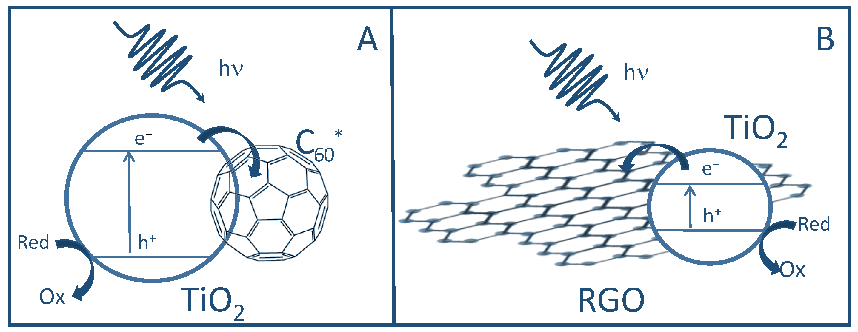
:1. Introduction
2. Results and Discussion
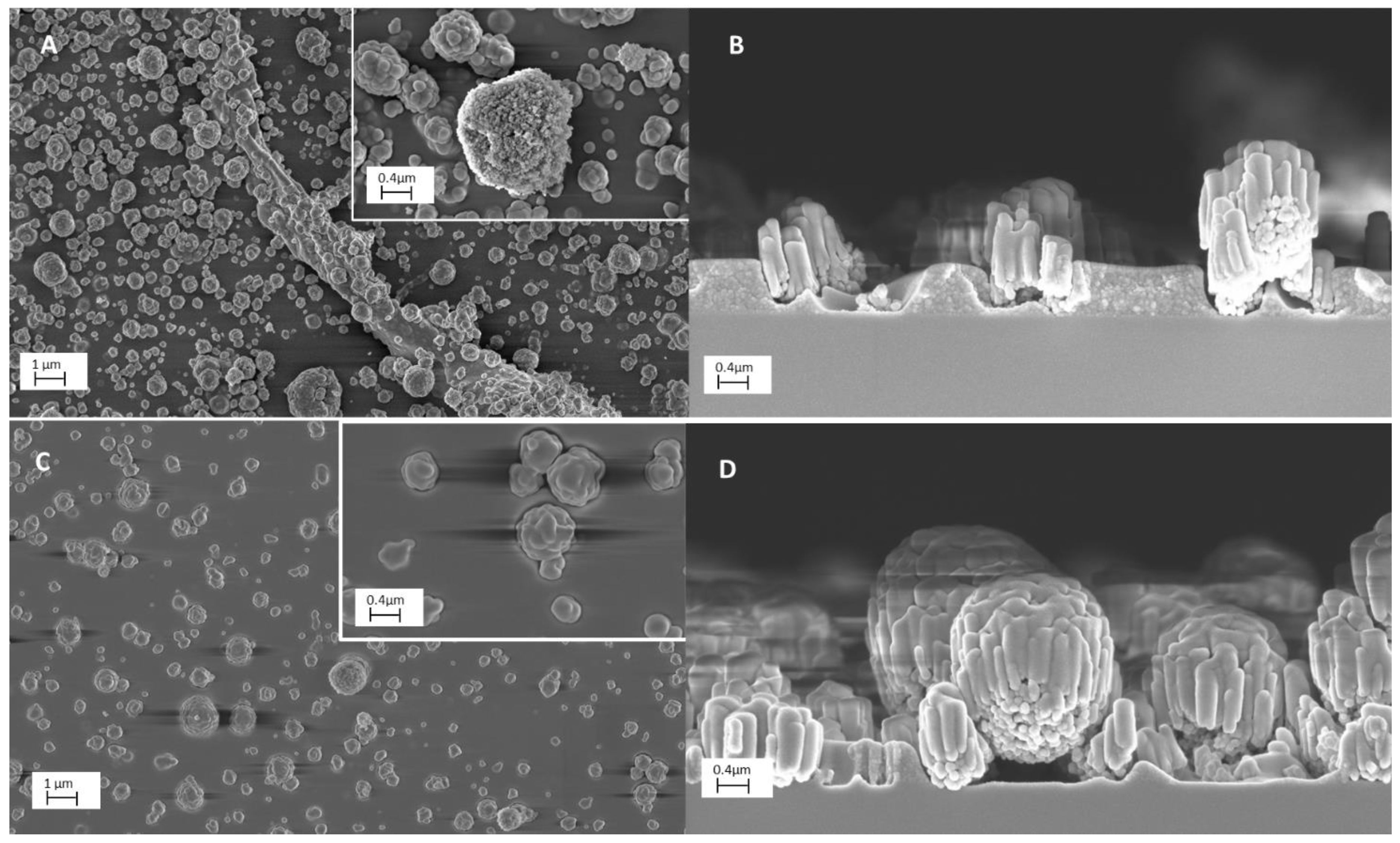
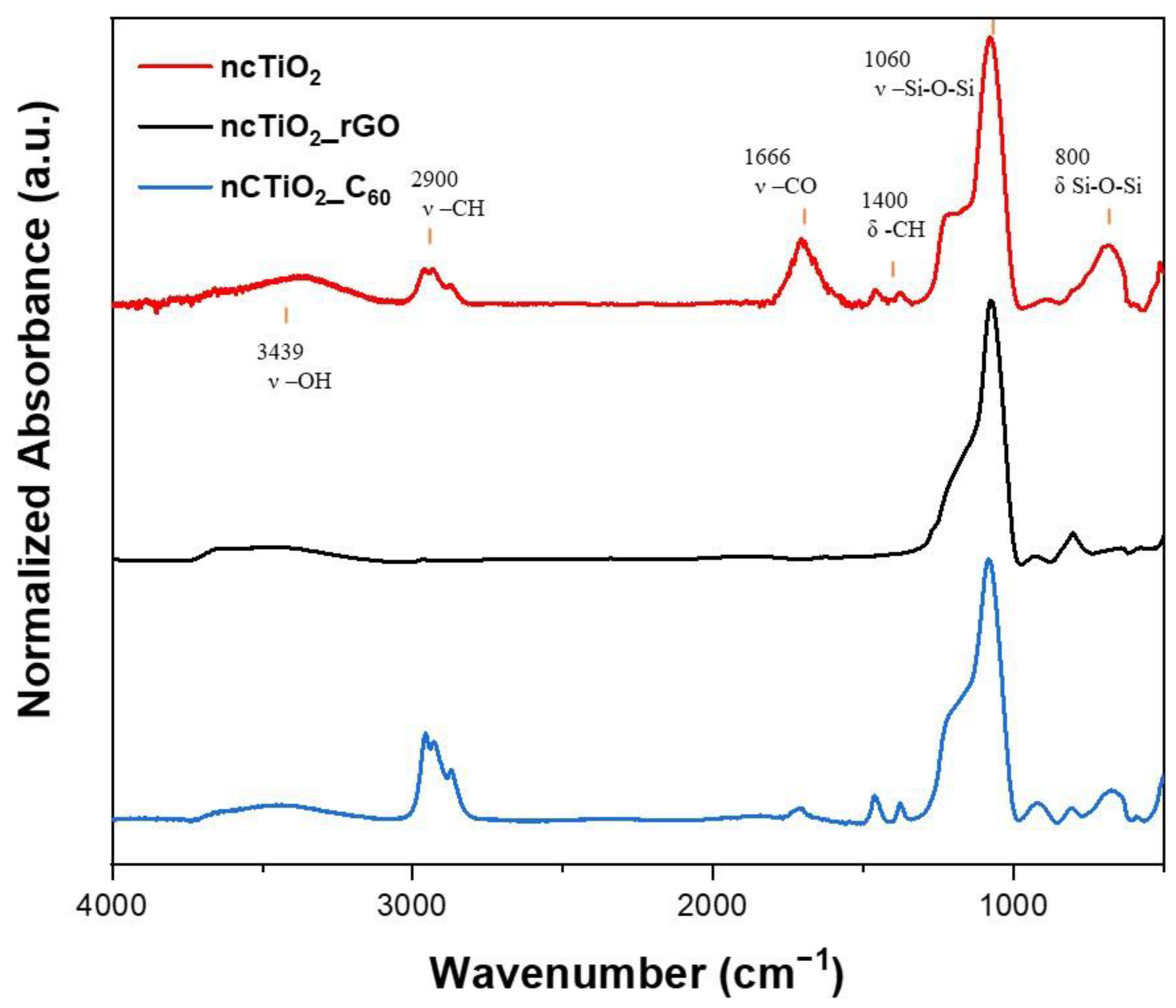
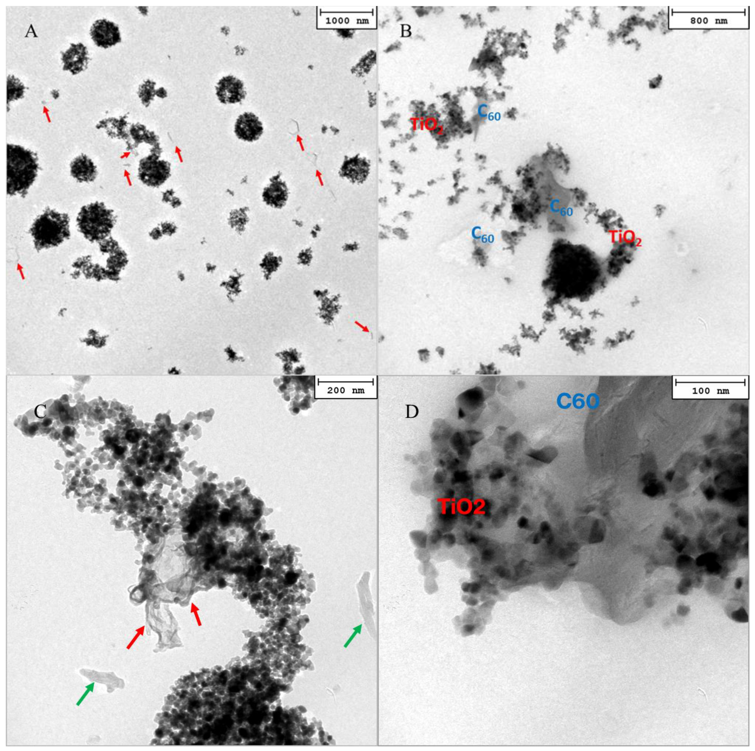
2.1. Nanocomposite Coatings Characterization
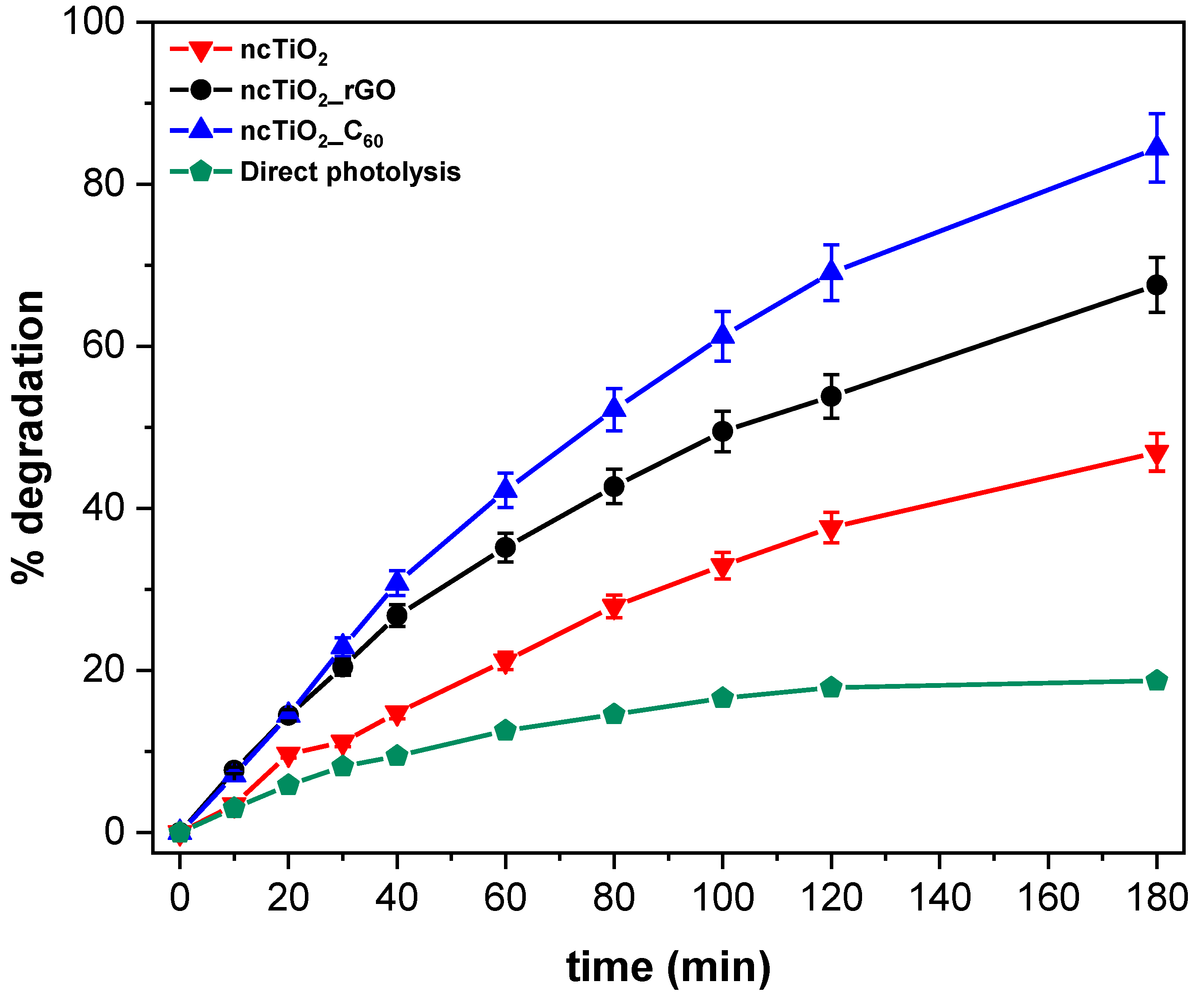
2.2. Photocatalytic Activity Evaluation
3. Materials and Methods
3.1. Suspensions Preparation
3.2. Plasma Deposition of Nanocomposite Coatings
3.3. Nanocomposite Coatings Characterization
3.4. Photocatalytic Activity Evaluation
4. Conclusions
Supplementary Materials
Author Contributions
Funding
Institutional Review Board Statement
Informed Consent Statement
Data Availability Statement
Acknowledgments
Conflicts of Interest
References
- Jayesh, C.; Kar, K.K. Recent progress in nanocomposites based on carbon nanomaterials and electronically conducting polymers. In Polymer Nanocomposites Based on Inorganic and Organic Nanomaterials; Scrivener Publishing: Beverly, MA, USA, 2015; pp. 229–256. [Google Scholar]
- Melinte, V.; Stroea, L.; Chibac-Scutaru, A.L. Polymer Nanocomposites for Photocatalytic Applications. Catalysts 2019, 12, 986. [Google Scholar] [CrossRef] [Green Version]
- Dell’Edera, M.; Porto, C.L.; Pasquale, I.D.; Petronella, F.; Curri, M.L.; Agostiano, A.; Comparelli, R. Photocatalytic TiO2-based coatings for environmental applications. Catalysis Today 2021, 380, 62–83. [Google Scholar] [CrossRef]
- Tong, Y.; Li, Y.; Xie, F.; Ding, M. Optical gas sensing of TiO2 and TiO2/Au nanocomposite thin films. Sens. Actuators B Chem. 2008, 132, 107–115. [Google Scholar]
- Khrenov, V.; Schwager, F.; Klapper, M.; Koch, M.; Muller, K. Compatibilization of inorganic particles for polymeric nanocomposites. Optimization of the size and the compatibility of ZnO particles. Polym. Bull. 2007, 58, 799–807. [Google Scholar] [CrossRef]
- Shameem, M.M.; Sasikanth, S.; Annamalai, R.; Raman, R.G. A brief review on polymer nanocomposites and its applications. Mater. Today Proc. 2021, 45, 2536–2539. [Google Scholar] [CrossRef]
- Banerjee, S.; Adhikari, E.; Sapkota, P.; Sebastian, A.; Ptasinska, S. Atmospheric Pressure Plasma Deposition of TiO2. Materials 2020, 13, 2931. [Google Scholar] [CrossRef]
- Palumbo, F.; Porto, C.L.; Fracassi, F.; Favia, P. Recent Advancements in the Use of Aerosol-Assisted Atmospheric Pressure Plasma Deposition. Coatings 2020, 10, 440. [Google Scholar] [CrossRef]
- Porto, C.L.; Dell, M.; De Pasquale, I.; Milella, A.; Fracassi, F.; Curri, M.L.; Comparelli, R.; Palumbo, F. Photocatalytic Investigation of Aerosol-Assisted Atmospheric Pressure Plasma Deposited Hybrid TiO2 Containing Nanocomposite Coatings. Nanomaterials 2022, 12, 3758. [Google Scholar] [CrossRef]
- Nakata, K.; Fujishima, A. TiO2 photocatalysis: Design and applications. J. Photochem. Photobiol. C Photochem. Rev. 2012, 13, 169–189. [Google Scholar] [CrossRef]
- Pawar, M.; Sendoğdular, S.T.; Gouma, P. A Brief Overview of TiO2 Photocatalyst for Organic Dye Remediation: Case Study of Reaction Mechanisms Involved in Remediation: Case Study of Reaction Mechanisms Involved in Ce-TiO2 Photocatalysts System. J. Nanomater. 2018, 2018, 13. [Google Scholar] [CrossRef] [Green Version]
- Kochuveedu, S.T.; Jang, Y.H.; Kim, D.H. A study on the mechanism for the interaction of light with noble metal-metal oxide semiconductor nanostructures for various photophysical applications. Chem. Soc. Rev. 2013, 42, 8467–8493. [Google Scholar] [CrossRef] [PubMed]
- Truppi, A.; Petronella, F.; Placido, T.; Margiotta, V.; Lasorella, G.; Giotta, L.; Giannini, C.; Sibillano, T.; Murgolo, S.; Mascolo, G.; et al. Gram-scale synthesis of UV–vis light active plasmonic photocatalytic anocomposite based on TiO2/Au nanorods for degradation of pollutants in water. Appl. Catal. B Environ. 2019, 243, 604–613. [Google Scholar] [CrossRef]
- Sampaio, M.J.; Silva, C.G.; Marques, R.R.N.; Silva, A.M.T.; Faria, J.L. Carbon nanotube–TiO2 thin films for photocatalytic applications. Catal. Today 2011, 161, 91–96. [Google Scholar] [CrossRef]
- Petronella, F.; Curri, M.L.; Striccoli, M.; Fanizza, E.; Mateo-Mateo, C.; Alvarez-Puebla, R.A.; Sibillano, T.; Giannini, C.; Correa-Duarte, M.A.; Comparelli, R. Direct growth of shape controlled TiO2 nanocrystals onto SWCNTs for highly active photocatalytic materials in the visible. Appl. Catal. B Environ. 2015, 178, 91–99. [Google Scholar] [CrossRef]
- Zhang, X.; Wang, Q.; Zou, L.-H.; You, J.-W. Facile fabrication of titanium dioxide/fullerene nanocomposite and its enhanced visible photocatalytic activity. J. Colloid Interface Sci. 2016, 466, 56–61. [Google Scholar] [CrossRef]
- Bhanvase, B.A.; Shende, T.P.; Sonawane, S.H. A review on graphene–TiO2 and doped graphene–TiO2 nanocomposite photocatalyst for water and wastewater treatment. Environ. Technol. Rev. 2017, 6, 1–14. [Google Scholar] [CrossRef]
- Andreozzi, M.; Álvarez, M.G.; Contreras, S.; Medina, F.; Clarizia, L.; Vitiello, G.; Llorca, J.; Marotta, R. Treatment of saline produced water through photocatalysis using rGO-TiO2 nanocomposites. Catal. Today 2018, 315, 194–204. [Google Scholar] [CrossRef] [Green Version]
- Yu, X.; Liu, J.; Yu, Y.; Zuo, S.; Li, B. Preparation and visible light photocatalytic activity of carbon quantum dots/TiO2 nanosheet composites. Carbon 2014, 68, 718–724. [Google Scholar] [CrossRef]
- Pant, B.; Park, M.; Park, S.-J. TiO2 NPs Assembled into a Carbon Nanofiber Composite Electrode by a One-Step Electrospinning Process for Supercapacitor Applications. Polymers 2019, 11, 899. [Google Scholar] [CrossRef] [Green Version]
- Bokare, A.; Chinnusamy, S.; Erogbogbo, F. TiO2-Graphene Quantum Dots Nanocomposites for Photocatalysis in Energy and Biomedical Applications. Catalysts 2021, 11, 319. [Google Scholar] [CrossRef]
- Leary, R.; Westwood, A. Carbonaceous nanomaterials for the enhancement of TiO2 photocatalysis. Carbon 2011, 49, 741–772. [Google Scholar] [CrossRef]
- Mondal, A.; Prabhakaran, A.; Gupta, S.; Subramanian, V.R. Boosting Photocatalytic Activity Using Reduced Graphene Oxide (RGO)/Semiconductor Nanocomposites: Issues and Future Scope. ACS Omega 2021, 6, 8734–8743. [Google Scholar] [CrossRef] [PubMed]
- Liang, H.; Xu, S.; Liu, W.; Sun, Y.; Liu, X.; Zheng, X.; Li, S.; Zhang, Q.; Zhu, Z.; Zang, X.; et al. Modulation of the work function of fullerenes C60 and C70 by alkali-metal adsorption: A theoretical study. Phys. Lett. A 2013, 377, 2676–2680. [Google Scholar] [CrossRef]
- Yang, M.-Q.; Zhang, N.; Xu, Y.-J. Synthesis of Fullerene–, Carbon Nanotube–, and Graphene–TiO2 Nanocomposite Photocatalysts for Selective Oxidation: A Comparative Study. ACS Appl. Mater. Interfaces 2013, 5, 1156–1164. [Google Scholar] [CrossRef]
- Attar, A.S.; Ghamsari, M.S.; Hajiesmaeilbaigi, F.; Mirdamadi, S. Modifier ligands effects on the synthesized TiO2 nanocrystals. J. Mater. Sci. 2008, 43, 1723–1729. [Google Scholar] [CrossRef]
- Coclite, A.M.; Milella, A.; Palumbo, F.; Pen, C.L.; d’Agostino, R. Plasma Deposited Organosilicon Multistacks for High-Performance Low-Carbon Steel Protection. Plasma Process Polym. 2010, 7, 802–812. [Google Scholar] [CrossRef]
- Vázquez-Valerdi, D.E.; Luna-López, J.A.; Carrillo-López, J.; García-Salgado, G.; Benítez-Lara, A.; Espinosa-Torres, N.D. Compositional and optical properties of SiOx films and (SiOx/SiOy) junctions deposited by HFCVD. Nanoscale Res. Lett. 2014, 9, 422. [Google Scholar] [CrossRef] [Green Version]
- Hotze, E.M.; Labille, J.; Alvarez, P.; Wiesner, M. Mechanisms of Photochemistry and Reactive Oxygen Production by Fullerene Suspensions in Water. Environ. Sci. Technol. 2008, 42, 4175–4180. [Google Scholar] [CrossRef]
- Chae, S.R.; Hotze, E.M.; Wiesner, M. Possible Applications of Fullerene Nanomaterials in Water Treatment and Reuse. In Nanotechnology Application for Clean Water, 2nd ed.; William Andrew Publishing: Norwich, NY, USA, 2014; pp. 329–338. [Google Scholar]
- Kamat, P.V.; Gevaert, M.; Vinodgopal, K. Photochemistry on Semiconductor Surfaces. Visible Light Induced Oxidation of C60 on TiO2 Nanoparticles. J. Phys. Chem. B 1997, 101, 4422–4427. [Google Scholar] [CrossRef]
- Pan, Y.; Liu, X.; Zhang, W.; Liu, Z.; Zeng, G.; Shao, B.; Lian, Q.; He, Q.; Yuan, X.; Huang, D.; et al. Advances in photocatalysis based on fullerene C60 and its derivatives: Properties, mechanism, synthesis, and applications. Appl. Catal. B Environ. 2020, 265, 118579. [Google Scholar] [CrossRef]
- Guex, L.G.; Sacchi, B.; Peuvot, K.F.; Andersson, R.L.; Pourrahimi, A.M.; Ström, V.; Farris, S.; Olsson, R.T. Experimental review: Chemical reduction of graphene oxide (GO) to reduced graphene oxide (rGO) by aqueous chemistry. Nanoscale 2017, 9, 9562–9571. [Google Scholar] [CrossRef] [PubMed] [Green Version]
- Ortiz-López, J.; Gómez-Aguilar, R. Dielectric permittivity and AC cunductivity in polycrystalline and amorphous C60. Rev. Mex. De Física 2003, 49, 529–536. [Google Scholar]
- Porto, C.L.; Palumbo, F.; Buxadera-Palomero, J.; Canal, C.; Jelinek, P.; Zajickova, L.; Favia, P. On the plasma deposition of vancomycin-containing nano-capsules for drug-delivery applications. Plasma Process. Polym. 2018, 15, 1700232. [Google Scholar] [CrossRef]
- Houas, A.; Lachheb, H.; Ksibi, M.; Elaloui, E.; Guillard, C.; Herrmann, J.-M. Photocatalytic degradation pathway of methylene blue in water. Appl. Catal. B Environ. 2001, 31, 145–157. [Google Scholar] [CrossRef]


| Sample | Thickness |
|---|---|
| ncTiO2 | 1210 ± 280 nm |
| ncTiO2_rGO | 870 ± 140 nm |
| ncTiO2_C60 | 1690 ± 90 nm |
| Sample | %Ti | Ti/Si | C/Si |
|---|---|---|---|
| ncTiO2 | 1.7 | 0.04 | 0.85 |
| ncTiO2_rGO | 3.0 | 0.05 | 0.07 |
| ncTiO2_C60 | 0.5 | 0.02 | 1.82 |
| Sample | MB Deg (%) | k (min−1) | R2 |
|---|---|---|---|
| ncTiO2 | 47 ± 2 | 0.0041 | 0.99 |
| ncTiO2_rGO | 68 ± 3 | 0.0078 | 0.99 |
| ncTiO2_C60 | 85 ± 4 | 0.0109 | 0.98 |
| rGO nanocomposite (TiO2-free) | 23 ± 1 | 0.0021 | 0.99 |
| C60 nanocomposite (TiO2-free) | 44 ± 2 | 0.0060 | 0.99 |
| Direct photolysis | 19 ± 1 | 0.0029 | 0.99 |
| Sample | Aerosol 1 | Aerosol 2 |
|---|---|---|
| ncTiO2_rGO | TiO2 (10 mg/mL) IPA/HMDSO (90/10 v/v) He 2.5 slm | rGO (1 mg/mL) DDW He 3.5 slm |
| ncTiO2_C60 | TiO2 (10 mg/mL) IPA/HMDSO (90/10 v/v) He 2.5 slm | C60 (1 mg/mL) DDW He 3.5 slm |
| ncTiO2 | TiO2 (10 mg/mL) IPA/HMDSO (90/10 v/v) | DDW He 3.5 slm |
Disclaimer/Publisher’s Note: The statements, opinions and data contained in all publications are solely those of the individual author(s) and contributor(s) and not of MDPI and/or the editor(s). MDPI and/or the editor(s) disclaim responsibility for any injury to people or property resulting from any ideas, methods, instructions or products referred to in the content. |
© 2023 by the authors. Licensee MDPI, Basel, Switzerland. This article is an open access article distributed under the terms and conditions of the Creative Commons Attribution (CC BY) license (https://creativecommons.org/licenses/by/4.0/).
Share and Cite
Del Sole, R.; Lo Porto, C.; Lotito, S.; Ingrosso, C.; Comparelli, R.; Curri, M.L.; Barucca, G.; Fracassi, F.; Palumbo, F.; Milella, A. Atmospheric Pressure Plasma Deposition of Hybrid Nanocomposite Coatings Containing TiO2 and Carbon-Based Nanomaterials. Molecules 2023, 28, 5131. https://doi.org/10.3390/molecules28135131
Del Sole R, Lo Porto C, Lotito S, Ingrosso C, Comparelli R, Curri ML, Barucca G, Fracassi F, Palumbo F, Milella A. Atmospheric Pressure Plasma Deposition of Hybrid Nanocomposite Coatings Containing TiO2 and Carbon-Based Nanomaterials. Molecules. 2023; 28(13):5131. https://doi.org/10.3390/molecules28135131
Chicago/Turabian StyleDel Sole, Regina, Chiara Lo Porto, Sara Lotito, Chiara Ingrosso, Roberto Comparelli, Maria Lucia Curri, Gianni Barucca, Francesco Fracassi, Fabio Palumbo, and Antonella Milella. 2023. "Atmospheric Pressure Plasma Deposition of Hybrid Nanocomposite Coatings Containing TiO2 and Carbon-Based Nanomaterials" Molecules 28, no. 13: 5131. https://doi.org/10.3390/molecules28135131